Table of Contents
Advertisement
Quick Links
Advertisement
Table of Contents

Related Manuals for Nature Power 37002


Summary of Contents for Nature Power 37002
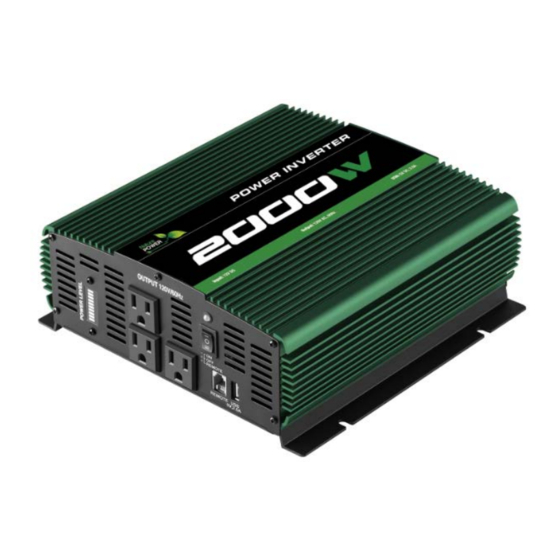
- Page 1 V1.1-M 28Apri2020 User Manual WARNING Read carefully and understand all ASSEMBLY AND OPERATION,INSTRUCTIONS before operating. Failure to follow the safety rules and other basic safety,precautions may result in serious personal injury. Item #37002 SAVE THESE INSTRUCTIONS...
- Page 2 T an you for c oosin a Nature Po er Pro uct This product is designed for certain applications only. Distributor cannot be responsible for issues arising from modification. We strongly recommend this product not be modified and/or used for any application other than that for which it was designed. If you have a question relative to a particular application, o not use the product until you have first contacted the distributor to determine if it can or should be performed on the product.
-
Page 3: Important Safety Instructions
IMPORTANT SAFETY INSTRUCTIONS SAVE THESE INSTRUCTIONS. 1. SAVE THESE INSTRUCTIONS. maintenance or cleaning. Turning off This manual contains important safety controls will not reduce this risk. and operating instructions for power 7. For the most effective use, place the inverter 2000W .This manual will show power inverter on a flat surface. -
Page 4: Connecting Inverter Cables
FEATURES • High-speed cooling fans • ON/OFF rocker switch To keep the inverter cool, the fan turn on • LED indicator depend on temperature in the inverter. Green indicates Power ON The fans do not run when the inverter Red indicates Overload/Interruption is turned off. - Page 5 6. Attach the other end of the wire to a 2. From the POSITIVE (RED) and the properly grounded location: NEGATIVE (BLACK) terminals, remove Vehicle: Connect to the chassis, unpainted 3. Place the POSITIVE (RED) ring frame part, or engine block of the vehicle. connector onto the POSITIVE Fixed location: Connect to a ground rod (RED) inverter terminal.
- Page 6 OUTPUT POWER INDICATE LIGHT Page of 14...
- Page 7 OPERATING INSTRUCTIONS After mounting and connecting your provides AC power to connected Inverter according to the instructions in equipment by converting DC power from your vehicle’s battery.The green LED will this manual, use the ON/OFF/REMOTE illuminate to indicate it is working.You switch to choose the Inverter’s operating can then power the inverter ON/OFF mode.
-
Page 8: Power Source
indicating the Inverter is receiving power. Switch the inverter’s ON/OFF/REMOTE Switch the Inverter’s ON/OFF/REMOTE switch to the ON (I) or REMOTE (II) switch to the OFF (O) position. The positions. If using the remote position, green LED may flash briefly and/or the connect the cable connector to the RJ11 internal speaker may beep briefly. -
Page 9: Led Indicator And Shutdown Protection
LED INDICATOR AND SHUTDOWN PROTECTION The Green LED lights automatically when The continuous load demand from the the inverter is plugged into a 12 volt equipment or device being operated DC power source and is turned on. The exceeds the continuous load rating of Red LED lights, the alarm sounds and the inverter. -
Page 10: If The Inverter's Fuse Blows
IF THE INVERTER’S FUSE BLOWS polarity or a short circuit within the device which should not have to be replaced or equipment being operated. under normal operating conditions. A If a fuse does blow, take the inverter to blown fuse is usually caused by reverse MAINTENANCE AND STORAGE INSTRUCTIONS 1. -
Page 11: Troubleshooting
TROUBLESHOOTING PROBLEM POSSIBLE CAUSE SOLUTION Low or no output Poor contact at terminals OVP/ Disconnect and reconnect the 12V voltage. connections. OLP. Using incorrect type of voltmeter Use a true RMS reading meter. to test output voltage. Red LED is lit. The battery voltage is below 10 Recharge or replace the battery. -
Page 12: Specifications
SPECIFICATIONS Nominal input voltage ..................12.8-13.2 VDC Nominal output voltage ................115±10% VAC Output frequency ....................60±3 Hz Operating input voltage ................10.0-15.0 VDC Continuous output power ................Up to 2000 W Surge output power ....................4000 W Waveform ..................... Modified sine wave Efficiency (typical) ....................... -
Page 13: Limited Warranty
If defective part or unit should be returned, a Return Authorization Number must be issued by Nature Power and the defective part or unit should be returned to the authorized location at the purchasers’ expense. A dated proof of purchase is required to receive warranty service. - Page 14 Please contact Nature Power Products to acquire more information: 1-800-588-0590 info@naturepowerproducts.com www.naturepowerproducts.com Made in Taiwan Page 14 of 14...
Need help?
Do you have a question about the 37002 and is the answer not in the manual?
Questions and answers