
Subscribe to Our Youtube Channel
Related Manuals for Knight Team Table 4 Legs


Summary of Contents for Knight Team Table 4 Legs
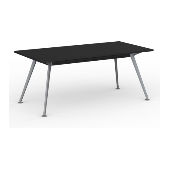
- Page 1 Team Table Assembly Instructions Tools Required: Powered Screwdriver, Rubber Mallet, 4mm and 6mm Allen Key. knightgroup.co.nz...
-
Page 2: Important Notes
Team Table Page 2 Assembly Instructions 4 Leg Frame 1800 x 800mm 2400 x 1200mm See Page 3 6 Leg Frame 3600 x 1200mm See Page 6 8 Leg Frame 4800 x 1200mm Follow 6 Leg Frame Instructions. IMPORTANT NOTES! Prior to installment, use or maintenance of the desk frame, any installer and any user of the desk must study this assembly and operation manual carefully, so as to... - Page 3 Team Table Page 3 4 Legs - 1800x800 & 2400x1200mm Assembly Instructions COMPONENTS Slot Nut x2 10 Table Top x1 Leg x4 Adjustable Foot x4 SCREWS Leg Cable Cover x4 M8x20mm Dome Head x2 Rail Lengths x2 M8x12mm Dome Head x8 Rail Widths x2 M8x20mm Cap Head x4 2 Way Connector x4...
- Page 4 Team Table Page 4 Page 4 4 Legs - 1800x800 & 2400x1200mm Assembly Instructions Assembly Instructions Step 2 Step 1 Loosely connect the M8x20mm dome head bolt and Slide the 2 way connectors over each leg, and securely slot nut through the rail spacer bracket. Slide spacer lock into place using M8x20mm cap head bolts.
- Page 5 Team Table Page 5 Page 5 4 Legs - 1800x800 & 2400x1200mm Assembly Instructions Assembly Instructions Step 5 Step 6 Ensure the worksurface is centered over the frame. Conceal any power box cables using the clip leg Pre-drill holes in the worksurface. Fully tighten all cable covers.
- Page 6 Team Table Page 6 6 Legs - 3600 x 1200mm Assembly Instructions COMPONENTS 10 Rail Spacer Bracket x7 Slot Nut x7 Leg x6 Table Top x1 Adjustable Foot x6 Leg Cable Cover x6 SCREWS Rail Lengths x4 M8x20mm Dome Head x7 Rail Widths x3 14 M8x12mm Dome Head x14 2 Way Connector x4...
- Page 7 Team Table Page 7 6 Legs - 3600 x 1200mm Assembly Instructions Step 1 Step 2 Slide the 2 way and 3 way connectors over each leg, Loosely connect the M8x20mm dome head bolt and and securely lock into place using M8x20mm cap slot nut through the rail spacer bracket.
- Page 8 Team Table Page 8 6 Legs - 3600 x 1200mm Assembly Instructions Step 5 Step 6 Ensure the worksurface is centered over the frame. Conceal any power box cables using the clip leg Pre-drill holes in the worksurface. Fully tighten all cable covers.
Need help?
Do you have a question about the Team Table 4 Legs and is the answer not in the manual?
Questions and answers