Table of Contents
Advertisement
Quick Links
Advertisement
Table of Contents

Related Manuals for IDEC FS1A-C11S


Summary of Contents for IDEC FS1A-C11S
- Page 1 FS9Z-B1218 FS1A-C11S Safety Controller SafetyOne User’s manual...
- Page 3 SAFETY PRECAUTIONS Carefully read this user’s manual to ensure correct operation before starting installation, wiring, operation, maintenance, and inspection of the SafetyOne. In this user’s manual, safety precautions are categorized in order of importance Warning and Caution, as follows: Warning Warning notices are used to emphasize that improper operation may cause severe personal injury or death.
- Page 4 Warning Calculate respective safety distances, taking into consideration the response time of the SafetyOne, safety devices to be connected to the SafetyOne, and each other device that forms a part of the system configuration. Applicable safety performance is dependent on each system configuration. ...
- Page 5 IEC/EN61496-1) Solid state output device PNP output (See Note 1) Non-contact interlock switch IDEC HS7A series, IDEC HS3A serise Safety relay Relay equipped with forced guide mechanism or conforming to EN50205 Contactor Contactor equipped with forced guide mechanism...
- Page 6 Caution SafetyOne is designed for installation within an enclosure. Do not install SafetyOne outside an enclosure. Install SafetyOne in enclosure rated IP54 or higher. Install SafetyOne in environments described in the catalog, instruction sheet, and user’s manual. If SafetyOne is used in places where it is subjected to high temperature, high humidity, condensation, corrosive gases, excessive vibrations, and excessive shocks then electrical shocks, fire hazard, or malfunction may result.
- Page 7 The contents of this manual are subject to change without notice. Thorough measures have been taken in preparing the contents of this manual; however, in the case you find an error or the like, please bring it to the attention of your IDEC sales representative.
-
Page 8: Table Of Contents
CONTENTS Chapter1 OVERVIEW ................................1-1 About the SafetyOne..............................1-1 Features of the SafetyOne ............................1-2 Chapter2 PRODUCT SPECIFICATIONS ..........................2-1 Parts Description............................... 2-1 General specifications............................... 2-2 Dimensions ................................2-4 Applicable standards ..............................2-5 Safety performance ..............................2-6 Safety input specifications ............................2-8 Start input specifications ............................ - Page 9 Logic 12A: The logic for apparatus with a two-hand control device ................ 5-81 Logic 12b: The logic constructing an OR circuit for various apparatus ..............5-93 Logic 12C: The logic constructing an OR circuit for apparatus with openings ............5-107 Logic 12d: Partial control logic for apparatus with openings .................
-
Page 11: Chapter1 Overview
OVERVIEW Chapter1 OVERVIEW This chapter provides an understanding of the SafetyOne. Make efficient use of the SafetyOne by thoroughly familiarizing yourself with its functions. About the SafetyOne The FS1A series of SafetyOne controllers provides safeguarding measures for various factory automation equipment and systems, including robots, production machinery, semiconductor manufacturing apparatus, food packaging machinery, and printing machinery. -
Page 12: Features Of The Safetyone
OVERVIEW Features of the SafetyOne You can configure safety circuits without the use of complicated external wiring or special software, thereby greatly reducing the number of developmental man-hours required for product certification and the training time of safety responsible persons. ... -
Page 13: Chapter2 Product Specifications
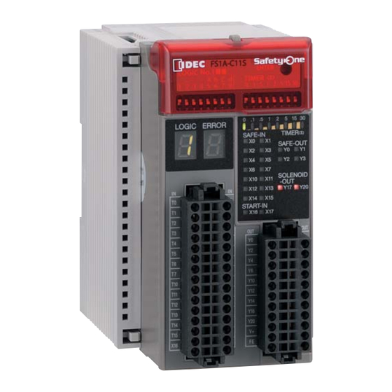
PRODUCT SPECIFICATIONS Chapter2 PRODUCT SPECIFICATIONS This chapter describes product specifications of the SafetyOne. Parts Description The protective cover is closed The protective cover is open Protective cover: The cover protects unauthorized changing of configuration switches. Input connector: Spring clamp connector for input devices. (Crimp connector can also be used.) Output connector: Spring clamp connector for output devices and power supply. -
Page 14: General Specifications
PRODUCT SPECIFICATIONS General specifications Operating conditions Operating temperature (Surrounding air -10 to +55 ºC (no freezing) temperature) Relative operating humidity 10 to 95% (non-condensing) Storage temperature -40 to +70 ºC (no freezing) Relative storage humidity 10 to 95% (non-condensing) Pollution degree 2 (IEC/EN 60664-1) Degree of protection IP20 (IEC/EN 60529) - Page 15 PRODUCT SPECIFICATIONS 25A maximum Inrush current Reverse polarity: No operation, no damage Affect of improper power supply connection Improper voltage: Permanent damage may occur Note1. Time to shut OFF safety outputs after safety inputs are turned OFF or input monitor error is detected (in case of OFF-delay timer is 0s).
-
Page 16: Dimensions
PRODUCT SPECIFICATIONS Dimensions Locking ring Detail of locking ring... -
Page 17: Applicable Standards
PRODUCT SPECIFICATIONS Applicable standards Standard Title IEC 61508 Part1-7 Functional safety of electrical/electronic/programmable electronic : 2010 safety-related systems EN ISO 13849-1 Safety of machinery -- Safety-related parts of control systems -- Part 1: : 2015 General principles for design IEC 62061 : 2005/A2: 2015 Safety of machinery - Functional safety of safety-related electrical, EN 62061... -
Page 18: Safety Performance
PRODUCT SPECIFICATIONS Safety performance In the case of using safety outputs as dual channel outputs, SafetyOne can be used in a system for control category B to 4 and performance level a to e in accordance with EN ISO13849-1. In the case of using safety outputs as single channel outputs, SafetyOne can be used in a system for control category B to 3 and performance level a to d in accordance with EN ISO13849-1. - Page 19 PRODUCT SPECIFICATIONS Mean Time To dangerous Failure (MTTF ) and diagnostic coverage (DC) ・ In the case of using safety outputs as dual channel outputs The following table describes MTTF and DC in the case of dual channel outputs. They are needed for the calculation of Performance Level (PL) which is applied to a system with SafetyOne.
-
Page 20: Safety Input Specifications
PRODUCT SPECIFICATIONS Safety input specifications Drive terminal specifications (T0, T1, T2, T3, T4, T5, T6, T7, T10, T11, T12, T13, T14, T15) Rated drive voltage Power supply voltage Power supply voltage – 2.0V Minimum drive voltage Number of drive terminals Note1 Maximum drive current 20mA per port (at 28.8V DC) -
Page 21: Start Input Specifications
PRODUCT SPECIFICATIONS Start input specifications Rated input voltage 24V DC Input ON voltage 15.0V DC to 28.8V DC Input OFF voltage Open or 0V DC to 5.0V DC Number of start input terminals 2 (X16,17) Input current 5mA per port (at rated voltage) Type of input Sink type input (for PNP output), Type 1 (EN61131-2) Note1... -
Page 22: Safety Output Specifications
PRODUCT SPECIFICATIONS Safety output specifications Output type Source output (N channel MOSFET) Rated output voltage Power supply voltage Minimum voltage Power supply voltage - 2.0V Number of output terminals 4 (Y0, Y1, Y2, Y3) Point 500mA maximum Maximum output current total 1A maximum Leakage current... -
Page 23: Monitor Output Specifications
PRODUCT SPECIFICATIONS Monitor output specifications Output type Source output (N channel MOSFET) Rated output voltage Power supply voltage Minimum output voltage Power supply voltage - 2.0V Number of outputs 11 (Y4, Y5, Y6, Y7, Y10, Y11, Y12, Y13, Y14, Y15, Y16) Point 20mA maximum Maximum output current... -
Page 24: Solenoid/Lamp Output Specifications
PRODUCT SPECIFICATIONS Solenoid/Lamp output specifications Output type Source output (N channel MOSFET) Rated output voltage Power supply voltage Minimum output voltage Power supply voltage - 2.0V Number of outputs 2 (Y17, Y20) point 500mA maximum Maximum output current total 500mA maximum Leakage current 0.1mA maximum Note1... -
Page 25: Logic Number
The logic number of the SafetyOne is composed by a 3-digit code as following. Example 1: LOGIC No.104 The first code “1” inidicates the type number “FS1A-C11S”. Following 2-digit code “04” indicates the state of the logic switch. The logic LED displays this 2-digit code. But “0” is not displayed. -
Page 26: Indicators
PRODUCT SPECIFICATIONS Indicators (1) Logic LED (green) 0 . 1 . 5 1 2 5 1 5 3 0 LOGIC ERROR (2) Error LED (red) TIM ER (S) SAFE-IN (3) Timer LED (green) SAFE-OUT (4) Input/Output status LED (orange) - SAFE-IN SOLENOID - START-IN -OUT... - Page 27 PRODUCT SPECIFICATIONS (3) Timer LED Indication Status Descriptions No OFF-delay (safety outputs shut off immediately) OFF-delay timer 0.1s OFF-delay timer 0.5s OFF-delay timer 1s OFF-delay timer 2s OFF-delay timer 5s OFF-delay timer 15s OFF-delay timer 30s Each LED Blink Selected timer value (Configuration state) Random ON/Blink Initializing (Initial state)
-
Page 28: Specification Of Configuration Switches
PRODUCT SPECIFICATIONS Specification of configuration switches TYPE (1) Logic switch (2) Timer switch (3) Enter button (1) Logic switch The logic switch is an 8-digit DIP switch for use in logic configuration. When one of “1” to ”8” is selected, or one of “1” to “4” and one of “A”, “b”, “C”, ”d” are selected, the corresponding logic in the SafetyOne is activated. -
Page 29: Connector Specifications
X1 X1 5 5 X1 X1 6 6 X1 X1 7 7 Connector type: - Spring clamp connector (30 poles) FS9Z-CN01 [IDEC] (Tyco Electronics Japan type Number: 2-1871940-5) Note1 - Crimp connector (30 poles) (Tyco Electronics Japan type Number: 2-1871946-5) - Page 30 Y1 Y1 7 7 Y1 Y1 6 6 FE FE FE FE Connector type: - Spring Clamp connector (22 poles) FS9Z-CN02 [IDEC] (Tyco Electronics Japan type No.:2-1871940-1) - Crimp connector (22 poles) Note1 (Tyco Electronics Japan type No.: 2-1871946-1) Terminal...
-
Page 31: Chapter3 Installation And Wiring
INSTALLATION AND WIRING Chapter3 INSTALLATION AND WIRING This chapter describes methods and precautions for installing and wiring the SafetyOne. Before starting installation and wiring, be sure to read “SAFETY PRECAUTIONS” in the beginning of this manual and understand the precautions described under WARNING and CAUTION. WARNIG and CAUTION Warning ●... - Page 32 INSTALLATION AND WIRING ● Environment for using the SafetyOne is “Pollution degree 2”. Use SafetyOne in environments of pollution degree 2 (according to IEC/EN 60664-1). ● Prevent SafetyOne from falling while moving or transporting otherwise damage or malfunction of the SafetyOne may result. ●...
-
Page 33: Installation Method
INSTALLATION AND WIRING Installation method ■ Installation location and direction When the SafetyOne is installed in an enclosure, confirm that installation environments meet the product specifications. Using in environments as a described below, (over the product specifications) may cause fire hazard, damage, or malfunction. - SafetyOne should not be exposed to excessive dust, dirt, salt, vibration or shocks. - Page 34 INSTALLATION AND WIRING Mount SafetyOne on a vertical plane as shown in Fig.3.2. All other installation directions are not allowed. BNL6 mounting clip Fig. 3.2 Correct installation direction Upwards Sideways Downwards Fig. 3.3 Incorrect installation directions...
- Page 35 2. With the top of SafetyOne unit facing up, as shown in Fig. 3.4, insert the groove, on the rear of the unit, and press the unit in the direction of the arrow. 3. Use BNL6 (IDEC) mounting clips (sold separately) on both sides to prevent it from moving sideways.
-
Page 36: Wiring Method
Note1. For detailed information of Crimp connector, consult Tyco Electronics AMP. ■ Applicable connectors and mounting to SafetyOne Applicable connectors Type No. of pole Part No. Remarks FS9Z-CN01 IDEC (optional) 2-1871940-5 Tyco Electronics Japan Spring clamp FS9Z-CN02 IDEC (optional) 2-1871940-1 Tyco Electronics Japan... - Page 37 INSTALLATION AND WIRING ■ Wiring for spring clamp connector Do not wire the connector while it is connected to the SafetyOne, as this can damage the connector and the SafetyOne. To connect the wire, use a connecting tool (Tyco Electronics Japan Type Number: 1891348-1) or a commercially-available screwdriver.
- Page 38 INSTALLATION AND WIRING...
-
Page 39: Chapter4 Basic Operations
BASIC OPERATIONS Chapter4 BASIC OPERATIONS This chapter describes the basic operations of SafetyOne. Make proper use of the SafetyOne by thoroughly familiarizing yourself with basic operations and functions. Internal states The SafetyOne operates in five internal states, as shown in Table 4.1. The LED display and output status for each state are shown in Table 4.2.1and 4.2.2. - Page 40 BASIC OPERATIONS (1) Random display of Initial state. (2) Output and LED display of the selected logic. (3) Blinking LED display of the selected logic number or the selected timer value. (4) Pulsing display of monitor output and output LED corresponding to the input of error. Other LEDs and monitor outputs maintain the display of Run state.
-
Page 41: Turning On The Power
BASIC OPERATIONS Turning on the power After the SafetyOne is turned on, it transitions to the Initial state and checks internal circuits. SafetyOne changes to the appropriate state (in approximately 6s) according to the result of the internal circuit check. During the Initial state, the LEDs blink to check operation. Logic switch and timer switch are set Logic: “101”... -
Page 42: Logic Configuration
BASIC OPERATIONS Logic configuration The SafetyOne offers 24 types of logic, and by performing the logic configuration procedure listed below, you can enable the desired logic. The SafetyOne can transition to the Configuration state from the Run or Protection state. Configuration operations are disabled in the Initial and Stop states. - Page 43 BASIC OPERATIONS 3. Confirm the configuration and press the TYPE enter button. Confirm that the selected logic switch matches the blinking logic LED, and then press the enter 0 .1 .5 1 2 5 15 30 LOGIC ERROR button by using configuration tool. TIMER(S) SAFE-IN SAFE-OUT...
-
Page 44: Timer Configuration
BASIC OPERATIONS Timer configuration SafetyOne has an OFF-delay timer function that retains safety outputs during the configured time and after that turns OFF the safety outputs. You can use this function to configure stop category "0" or "1". Perform the configuration procedure listed below to configure the OFF-delay timer to one of the following eight settings, using the same procedure as that for configuring the logic: 0, 0.1, 0.5, 1, 2, 5, 15 or 30 s. - Page 45 BASIC OPERATIONS 3. Confirm the configuration and press the TYPE enter button. Confirm that the selected timer switch matches the blinking timer LED, and then press the enter 0 .1 .5 1 2 5 15 30 LOGIC ERROR TIMER(S) SAFE-IN button by using the configuration tool.
-
Page 46: Canceling The Protection State
BASIC OPERATIONS Canceling the Protection state SafetyOne transitions to the Protection state if a failure is detected in an external device or an error is detected in external wiring, such as when different operations are performed between dual channel inputs or two muting inputs, when the EDM input is OFF while the safety outputs are transitioning from OFF to ON or the EDM input is ON while the safety outputs are transitioning from ON to OFF by output control. -
Page 47: Canceling The Stop State
BASIC OPERATIONS Warning Turn OFF the power to SafetyOne before inspection and/or connecting of the wires. Canceling the Stop state If the SafetyOne detects any wiring errors, abnormalities or internal circuit failure, it changes to the Stop state and locks out operations. The Stop state can be cancelled by the following method. - Page 48 BASIC OPERATIONS 4-10...
-
Page 49: Chapter5 Logic
1 3C → → → 1 3d Mode selection is A two-hand control → → → → → 1 2A FS1A-C11S not needed device is used Safety light The Muting → curtains → function of FS1A → 1 1d FS1A-C11S... - Page 50 LOGIC 0 01 General-purpose logic for various apparatus 0 02 General-purpose logic for NO/NC contact inputs 0 03 General-purpose logic for apparatus with openings 0 04 Muting function logic for apparatus with openings General-purpose logic for devices for which synctime 0 05 between contacts cannot be specified The logic applicable for selection...
-
Page 51: Safety Performance On Each Wiring Of Inputs And Outputs
LOGIC Safety performance on each wiring of inputs and outputs Applicable safety performance of SafetyOne depends on wiring of the inputs and outputs. Wiring examples and achivable safety performances are shown below. Wiring example of dual channel safety inputs Control category 4 MTTF 100 years... - Page 52 LOGIC Wiring example of safety outputs Control category 4 MTTF 100 years d DC high PL e 0V DC SafetyOne External Device Monitor K : Contactor M : Motor Control category 3 Note: MTTF 100 years To avoid short circuit between each cable, d ...
- Page 53 LOGIC Wiring example of a SafetyOne and a SafetyOne Control category 4 MTTF 100 years d DC high PL e SafetyOne SafetyOne Dual Channel Safety Control category 3 MTTF 100 years d DC Medium PL d Note: To avoid short circuit between each cable, -Fix the cables permanently and protect against external damage, e.g.
- Page 54 LOGIC Using IDEC non-contact interlock switches HS7A series S1, 2 : HS7A-DMC59** (1NO+1NC Contact, with LED / without LED) or HS7A-DMP50** (1NO+2NC Contact, with LED / without LED) S3, 4, 5 : HS7A-DMC790* (2NO Contact, without LED) or HS7A-DMP700* (2NO+1NC Contact, without LED)
- Page 55 LOGIC Note 5) Maximum number of HS7A switches for each safety input is shown below. HS7A Switch With out LED With LED Dual channel NO/NC input Dual channel direct opening input Not applicable Dual channel dependent input Note 6) In the common connection of several non-contact interlock switches, applicable safety performance depends on result of risk assessment for whole of the safety configuration.
-
Page 56: Logic 101: The Logic For Various Apparatus
LOGIC Logic 101: The logic for various apparatus Overview (Logic 101) This logic is for safety protective measures applicable to production machines and robots. Safety outputs perform as dual channel outputs. This logic enables the connection of 2 dual channel direct opening inputs and 4 dual channel dependent inputs. - Page 57 LOGIC Logic circuit (Logic 101) Safety input 5 Dual Channel Direct Opening T10, X10, T11, X11 Safety input 6 Dual Channel Direct Opening T12, X12, T13, X13 Safety input 1 Dual Channel Self-hold Dependent Safety output 1 T0, X0, T1, X1 function circuit 1 Hold &...
- Page 58 LOGIC Functions (Logic 101) ●Safety inputs: X0 to X13 (T0 to T13) Safety inputs are used to diagnose the status of connected safety devices, such as emergency stop switches, and interlock switches. Intended inputs Function (Terminal names) Safety input 1 Function name Dual channel dependent input (X0-T0, X1-T1)
- Page 59 LOGIC ●External device monitor inputs: X14 and X15 (T14 and T15) External device monitor inputs are used to diagnose the status of devices connected to safety outputs. Intended inputs Target safety Function (Terminal names) outputs (Terminal names) External device monitor input 1 Safety output 1 Function name External device monitor input...
- Page 60 LOGIC ●Start inputs: X16 and X17 Start inputs are used to control the start of safety outputs. Intended inputs Target safety inputs Function (Terminal names) (Terminal names) Start input 1 Safety input 1 Function name Monitor input (X16) (X0-T0, X1-T1) Symbol Single Channel Safety input 2...
- Page 61 LOGIC ●Safety outputs: Y0 to Y3 Safety outputs are used to output safety information processed by SafetyOne. Intended outputs Function (Terminal names) Safety output 1 Function name Safety output without timer (Y0, Y1) Symbol Hold OSSD Description of operation This function is a safety output to output safety information processed by SafetyOne.
- Page 62 LOGIC ●Safety input monitor outputs: Y4 to Y11 Safety input monitor outputs are used to output the status of safety inputs in SafetyOne. Intended outputs Target safety inputs Description of operation (Terminal names) (Terminal names) Safety input 1 monitor output Safety input 1 When the target safety input is ON, (Y4)
- Page 63 LOGIC ●Solenoid outputs: Y17 and Y20 Solenoid outputs are used to control a solenoid in an interlock switch. Intended outputs Description of operation (Terminal names) Solenoid output 1 When safety output 1 is OFF, the solenoid output is ON. When safety (Y17) Output 1 is ready to turn ON (safety output 1 can be turned ON by operation of the start input), the solenoid output is OFF.
- Page 64 LOGIC Wiring example (Logic 101) In the case where 3 interlock switches, 2 interlock switches with solenoid (spring lock type), and 1 emergency stop switch are connected. S1, 2, 3 :Interlock switch S4, 6 :Interlock switch with solenoid (spring lock type) :Emergency stop switch :Start switch S8, 9...
- Page 65 LOGIC When not using the start switch When connecting multiple emergency (Auto start) stop switches in series 24V DC When not detecting the welding of start switch (Manual start) 24V DC NOTE: Safety performance depends on the system configuration. When not using some inputs ・If there are unused safety inputs, connect the unused receive terminals to the corresponding drive terminals.
- Page 66 LOGIC Timing chart (Logic 101) Example: Manual start input (X16) is used. Example: Control start input (X17) is used. Safety Safety Power Power output output note 1) (note 1) Safety input 1: X0 Safety input 1: X0 note 1) (note 1) Safety input 1: X1 Safety input 1: X1 Monitor output for...
-
Page 67: Logic 11A: The Logic For Apparatus With Openings
LOGIC Logic 11A: The logic for apparatus with openings Overview (Logic 11A) This logic is for using safety devices with dual channel solid state outputs, such as safety light curtains, for safety protective measures of production machinery and robots. Safety outputs perform as dual channel outputs. - Page 68 LOGIC Logic circuit (Logic 11A) Safety input 5 Dual Channel Direct Opening T10, X10, T11, X11 Safety input 6 Dual Channel Direct Opening T12, X12, T13, X13 Safety input 1 Dual Channel Saefty Self-hold Safety output 1 X0, X1 function circuit 1 Hold &...
- Page 69 LOGIC Functions (Logic 11A) ●Safety inputs: X0 to X13 (T10 to T13) Safety inputs are used to diagnose the status of connected safety devices, such as emergency stop switches, and interlock switches. Intended inputs Function (Terminal names) Safety input 1 Function name Dual channel safety input (X0, X1)
- Page 70 LOGIC ●External device monitor inputs: X14 and X15 (T14 and T15) External device monitor inputs are used to diagnose the status of devices connected to safety outputs. Intended inputs Target safety Function (Terminal names) outputs (Terminal names) External device monitor input 1 Safety output 1 Function name External device monitor input...
- Page 71 LOGIC ●Start inputs: X16 and X17 Start inputs are used to control the start of safety outputs. Intended inputs Target safety inputs Function (Terminal names) (Terminal names) Start input 1 Safety input 1 Function name Monitor input (X16) (X0, X1) Symbol Single Channel Safety input 2...
- Page 72 LOGIC ●Safety outputs: Y0 to Y3 Safety outputs are used to output safety information processed by SafetyOne. Intended outputs Function (Terminal names) Safety output 1 Function name Safety output without timer (Y0, Y1) Symbol Hold OSSD Description of operation This function is a safety output to output safety information processed by SafetyOne.
- Page 73 LOGIC ●Safety input monitor outputs: Y4 to Y11 Safety input monitor outputs are used to output status of safety inputs in SafetyOne. Intended outputs Target safety inputs Description of operation (Terminal names) (Terminal names) Safety input 1 monitor output Safety input 1 When the target safety input is ON, (Y4) (X0, X1)
- Page 74 LOGIC ●Solenoid outputs: Y17 and Y20 Solenoid outputs are used to control a solenoid in an interlock switch. Intended outputs Description of operation (Terminal names) Solenoid output 1 When safety output 1 is OFF, the solenoid output is ON. When safety (Y17) Output 1 is ready to turn ON (safety output 1 can be turned ON by operation of the start input), the solenoid output is OFF.
- Page 75 LOGIC Wiring example (Logic 11A) In the case where 4 safety light curtains, 1 emergency stop switch, and 1 interlock switch with solenoid (spring lock type) are connected. S1 to 4 :Safety light curtain :Emergency stop switch :Interlock switch with solenoid (spring lock type) :Start switch :Solenoid control switch (Pressing the solenoid control switches after closing the guard door,...
- Page 76 LOGIC When not using the start switch When connecting multiple emergency stop switches (Auto start) in series 24V DC When not detecting the welding of start switch (Manual start) 24V DC NOTE: Safety performance depends on the system configuration. When not using some inputs ・If there are unused safety inputs in S1 to S4, connect the unused receive terminals to 24V DC power supply (V+).
- Page 77 LOGIC Timing chart (Logic 11A) Example: Manual start input (X16) is used. Example: Control start input (X17) is used. Safety Safety Power Power output output note 1) note 1) Safety input 1: X0 Safety input 1: X0 note 1) note 1) Safety input 1: X1 Safety input 1: X1 Monitor output for...
- Page 78 LOGIC 5-30...
-
Page 79: Logic 11B: The Logic For Apparatus With No/Nc Contact Inputs
LOGIC Logic 11b: The logic for apparatus with NO/NC contact inputs Overview (Logic 11b) This logic function is for using dual channel NO/NC contact devices as safety protective measures for semiconductor manufacturing machines and food packaging machinery. Safety outputs perform as dual channel outputs. - Page 80 LOGIC Logic circuit (Logic 11b) Safety input 5 Dual Channel Direct Opening T10, X10, T11, X11 Safety input 6 Dual Channel Direct Opening T12, X12, T13, X13 Safety input 1 Dual Channel Self-hold NO/NC T0, X0, T1, X1 function circuit 1 Safety output 1 Hold &...
- Page 81 LOGIC Functions (Logic 11b) ●Safety inputs: X0 to X13 (T0 to T13) Safety inputs are used to diagnose the status of connected safety devices, such as emergency stop switches, interlock switches, and non-contact interlock switches. Intended inputs Function (Terminal names) Safety input 1 Function name Dual channel NO/NC input...
- Page 82 LOGIC Unused safety inputs Terminal names Connection Safety input 1 X0-T0 Open X1-T1 Short Safety input 2 X2-T2 Open X3-T3 Short Safety input 3 X4-T4 Open X5-T5 Short Safety input 4 X6-T6 Open X7-T7 Short Safety input 5 X10-T10 Short X11-T11 Short Safety input 6...
- Page 83 LOGIC ●Start inputs: X16 and X17 Start inputs are used to control the start of safety outputs. Intended inputs Target safety inputs Function (Terminal names) (Terminal names) Start input 1 Safety input 1 Function Name Monitor input (X16) (X0-T0, X1-T1) Symbol Single Channel Safety input 2...
- Page 84 LOGIC ●Safety outputs: Y0 to Y3 Safety outputs are used to output safety information processed by SafetyOne. Intended outputs Function (Terminal names) Safety output 1 Function name Safety output without timer (Y0, Y1) Symbol Hold OSSD Description of operation This function is a safety output to output safety information processed by SafetyOne.
- Page 85 LOGIC ●Safety input monitor outputs: Y4 to Y11 Safety input monitor outputs are used to output the status of safety inputs in SafetyOne. Intended outputs Target safety inputs Description of operation (Terminal names) (Terminal names) Safety input 1 monitor output Safety input 1 When the target safety input is ON, (Y4)
- Page 86 LOGIC ●Solenoid outputs: Y17 and Y20 Solenoid outputs are used to control the solenoid in interlock switch with lock. Intended outputs Description of operation (Terminal Names) Solenoid output 1 When safety output 1 is OFF, the solenoid output is ON. When safety (Y17) Output 1 is ready to turn ON (safety output 1 can be turned ON by operation of the start input), the solenoid output is OFF.
- Page 87 LOGIC Wiring example (Logic 11b) In the case where 4 non-contact interlock switches, 1 emergency stop switch, and 1 interlock switch with solenoid (spring lock type) are connected. S1 to 4 :Non-contact interlock switch :Emergency stop switch :Interlock switch with solenoid (spring lock type) :Start switch :Solenoid control switch (Pressing the solenoid control switches after closing the guard door,...
- Page 88 LOGIC When not using the start switch When connecting multiple components in series (Auto start) 24V DC When not detecting the welding of start switch (Manual start) 24V DC When detecting the welding of start switch (Control start) 24V DC NOTE: Safety performance depends on the system configuration.
- Page 89 LOGIC Timing chart (Logic 11b) Example: Manual start input (X16) is used. Example: Control start input (X17) is used. Safety Safety Power Power output output note 1) note 1 ) Safety input 1: X0 Safety input 1: X0 note 1 ) note 1)...
- Page 90 LOGIC 5-42...
-
Page 91: Logic 11C: The Logic For Apparatus With Openings
LOGIC Logic 11C: The logic for apparatus with openings Overview (Logic 11C) This logic is for using safety devices with dual channel solid state outputs, such as safety light curtains, for safety protective measures of production machinery and robots. Safety outputs perform as dual channel outputs. - Page 92 LOGIC Logic circuit (Logic 11C) Safety input 3 Dual Channel Direct Opening T4, X4, T5, X5 Safety input 4 Dual Channel Direct Opening T6, X6, T7, X7 Safety input 5 Dual Channel Self-hold Direct Opening Safety output 1 T10, X10, T11, X11 function circuit 1 Hold &...
- Page 93 LOGIC Functions (Logic 11C) ●Safety inputs: X0 to X13 (T4 to T13) Safety inputs are used to diagnose the status of connected safety devices, such as emergency stop switches, and interlock switches. Intended inputs Function (Terminal names) Safety input 1 Function name Dual channel safety input (X0, X1)
- Page 94 LOGIC ●External device monitor inputs: X14 and X15 (T14 and T15) External device monitor inputs are used to diagnose the status of devices connected to safety outputs. Intended inputs Target safety Function (Terminal names) outputs (Terminal names) External device monitor input 1 Safety output 1 Function name External device monitor input...
- Page 95 LOGIC ●Start inputs: X16 and X17 Start inputs are used to control the start of safety outputs. Intended inputs Target safety inputs Function (Terminal names) (Terminal names) Start input 1 Safety input 1 Function name Monitor input (X16) (X0, X1) Symbol Single Channel Safety input 2...
- Page 96 LOGIC ●Safety outputs: Y0 to Y3 Safety outputs are used to output safety information processed by SafetyOne. Intended outputs Function (Terminal names) Safety output 1 Function name Safety output without timer (Y0, Y1) Symbol Hold OSSD Description of operation This function is a safety output to output safety information processed by SafetyOne.
- Page 97 LOGIC ●Safety input monitor outputs: Y4 to Y11 Safety input monitor outputs are used to output the status of safety inputs in SafetyOne. Intended outputs Target safety inputs Description of operation (Terminal names) (Terminal names) Safety input 1 monitor output Safety input 1 When the target safety input is ON, (Y4)
- Page 98 LOGIC ●Solenoid outputs: Y17 and Y20 Solenoid outputs are used to control a solenoid in an interlock switch. Intended outputs Description of operation (Terminal names) Solenoid output 1 When safety output 1 is OFF, the solenoid output is ON. When safety (Y17) Output 1 is ready to turn ON (safety output 1 can be turned ON by operation of the start input), the solenoid output is OFF.
- Page 99 LOGIC Wiring example (Logic 11C) In the case where 2 safety light curtains 2 emergency stop switches, and 2 interlock switches with solenoid (spring lock type) are connected. S1, 2 :Safety light curtain S3, 4 :Emergency stop switch S5, 6 :Interlock switch with solenoid (spring lock type) :Start switch S8, 9...
- Page 100 LOGIC When not using the start switch When connecting multiple components in series (Auto start) 24V DC When not detecting the welding of start switch (Manual start) 24V DC NOTE: Safety performance depends on the system configuration. When not using some safety inputs ・If there are unused safety inputs in S1 and S2, connect the unused receive terminals to 24V DC power supply (V+).
- Page 101 LOGIC Timing chart (Logic 11C) Example: Manual start input (X16) is used. Example: Control start input (X17) is used. Safety Safety Power Power output output note 1) note 1) Safety input 1: X0 Safety input 1: X0 note 1) note 1) Safety input 1: X1 Safety input 1: X1 Monitor output for...
- Page 102 LOGIC 5-54...
-
Page 103: Logic 11D: Muting Function Logic For Apparatus With Openings
LOGIC Logic 11d: Muting function logic for apparatus with openings Overview (Logic 11d) The logic is for using safety devices with dual channel solid state outputs, such as safety light curtains, and for devices with output muting signals that enable muting functions that temporarily suspend safety functions of safety devices for safety protective measures of robots and conveyor lines. - Page 104 LOGIC Logic circuit (Logic 11d) Safety input 3 Dual Channel Direct Opening T10, X10, T11, X11 Safety input 4 Dual Channel Direct Opening T12, X12, T13, X13 Safety input 1 Safety Dual Channel Safety input X0, X1 Muting function Ⅱ Self-hold Muting input 1 (...
- Page 105 LOGIC Functions (Logic 11d) ●Safety inputs: X0, X1, X4, X5, and X10 to X13 (T10 to T13) Safety inputs are used to diagnose the status of connected safety devices, such as emergency stop switches, and interlock switches. Intended inputs Function (Terminal names) Safety input 1 Function name...
- Page 106 LOGIC ●Muting inputs: X2, X3, X6, and X7 Muting inputs are used to diagnose the status of muting devices, such as sensors or limit switches. Intended inputs Target safety Function (Terminal names) inputs (Terminal names) Muting input 1 Safety input 1 Function name Muting input+Muting II (X2, X3)
- Page 107 LOGIC ●External device monitor inputs: X14 and X15 (T14 and T15) External device monitor inputs are used to diagnose the status of devices connected to safety outputs. Intended inputs Target safety Function (Terminal names) outputs (Terminal names) External device monitor input 1 Safety output 1 Function name External device monitor input...
- Page 108 LOGIC ●Start inputs: X16 and X17 Start inputs are used to control the start of safety outputs. Intended inputs Target safety inputs Function (Terminal names) (Terminal names) Start input 1 Safety input 1 Function name Monitor input (X16) (X0, X1) Symbol Single Channel Muting input 1...
- Page 109 LOGIC ●Safety outputs: Y0 to Y3 Safety outputs are used to output safety information processed by SafetyOne. Intended outputs Function (Terminal names) Safety output 1 Function name Safety output without timer (Y0, Y1) Symbol Hold OSSD Description of operation This function is a safety output to output safety information processed by SafetyOne.
- Page 110 LOGIC ●Safety input monitor outputs: Y4 to Y11 Safety input monitor outputs are used to output the status of safety inputs in SafetyOne. Intended outputs Target safety inputs Description of operation (Terminal names) muting inputs (Terminal names) Safety input 1 monitor output Safety input 1 When the target safety input or (Y4)
- Page 111 LOGIC ●Muting lamp outputs: Y17 and Y20 Muting lamp outputs are used to control muting lamps. Intended outputs Target safety inputs Description of operation (Terminal names) (Terminal names) Muting lamp output 1 Safety input 1 The output is ON, during safety input 1 is muting state by (Y17) (X0, X1) muting input 1.
- Page 112 LOGIC Wiring example (Logic 11d) In the case where 2 safety light curtains, 4 muting sensors, and 2 emergency stop switches are connected. S1, 4 :Safety light curtain S2, 3, 5, 6 :Muting sensor S7, 8 :Emergency stop switch :Start switch K1 to 4 :Contactor L1, 2...
- Page 113 LOGIC When not using the start switch When connecting multiple components in series (Auto start) 24V DC When not detecting the welding of start switch (Manual start) NOTE: Safety performance depends 24V DC on the system configuration. When not using some safety inputs ・If there are unused safety inputs in S1 and S4, connect the unused receive terminals to 24V DC power supply (V+).
- Page 114 LOGIC Timing chart (Logic 11d) Example: Manual start input (X16) is used. (Safety input 2, 3 and 4 are all ON and muting input 2 is OFF in this chart.) Note 1) When “Safety input 1” is turned OFF before “Muting input 1” is turned ON, muting function is not effective and all of “Safety output”...
- Page 115 LOGIC Example: Control start input (X17) is used. (Safety input 2, 3 and 4 are all ON and muting input 2 is OFF in this chart.) 5-67...
- Page 116 LOGIC 5-68...
-
Page 117: Logic 102: Partial Stop Logic For Apparatus With Openings
LOGIC Logic 102: Partial stop logic for apparatus with openings Overview (Logic 102) This logic is for using safety devices with dual channel solid state outputs, such as safety light curtains, for safety protective measures of production machinery and robots. Safety outputs perform as dual channel outputs. - Page 118 LOGIC Logic circuit (logic 102) Safety input 1 Dual Channel Direct Opening T0, X0, T1, X1 Safety output 1 Self-hold function circuit 1 Safety input 2 Dual Channel & Hold Direct Opening Hold T2, X2, T3, X3 OSSD Self-hold with function Off delay Safety input 3...
- Page 119 LOGIC Functions (Logic 102) ●Safety inputs: X0 to X13 (T0 to T5) Safety inputs are used to diagnose the status of connected safety devices, such as emergency stop switches, and interlock switches. Intended inputs Function (Terminal names) Safety input 1 Function name Dual channel direct opening input (X0-T0, X1-T1)
- Page 120 LOGIC ●External device monitor inputs: X14 and X15 (T14 and T15) External device monitor inputs are used to diagnose the status of devices connected to safety outputs. Intended inputs Target safety Function (Terminal names) outputs (Terminal names) External device monitor input 1 Safety output 1 Function name External device monitor input...
- Page 121 LOGIC ●Start inputs: X16 and X17 Start inputs are used to control the start of safety outputs. Intended inputs Target safety inputs Function (Terminal names) (Terminal names) Start input 1 Safety input 1 Function name Monitor input (X16) (X0-T0, X1-T1) Symbol Single Channel Safety input 2...
- Page 122 LOGIC ●Safety outputs: Y0 to Y3 Safety outputs are used to output safety information processed by SafetyOne. Intended outputs Function (Terminal names) Safety output 1 Function name Safety output with timer (Y0, Y1) Symbol Hold Safety output 2 OSSD (Y2, Y3) with Off delay Description of operation...
- Page 123 LOGIC ●Safety input monitor outputs: Y4 to Y11 Safety input monitor outputs are used to output the status of safety inputs in SafetyOne. Intended outputs Target safety inputs Description of operation (Terminal names) (Terminal names) Safety input 1 monitor output Safety input 1 When the target safety input is ON, (Y4)
- Page 124 LOGIC ●Solenoid outputs: Y17 and Y20 Solenoid outputs are used to control a solenoid in ian nterlock switch. Intended outputs Description of operation (Terminal names) Solenoid output 1 When safety output 1 is OFF, the solenoid output is ON. When safety (Y17) Output 1 is ready to turn ON (safety output 1 can be turned ON by operation of the start input), the solenoid output is OFF.
- Page 125 LOGIC Wiring example (Logic 102) In the case where 2 emergency stop switches, 1 interlock switch with solenoid (spring lock type), and 3 safety light curtains are connected. S1, 2 :Emergency stop switch :Interlock switch with solenoid (spring lock type) S4, 5, 6 :Safety light curtain :Start switch :Solenoid control switch...
- Page 126 LOGIC When connecting multiple components in series When not using the start switch (Auto start) 24V DC When not detecting the welding of start switch (Manual start) 24V DC NOTE: Safety performance depends on the system onfiguration. When not using some safety inputs ・If there are unused safety inputs in S1 to S3, connect the unused receive terminals to the corresponding drive terminals.
- Page 127 LOGIC Timing chart (Logic 102) Example: Manual start input (X16) is used. Safety Safety Power output output note 1) Safety input 1: X0 note 1) Safety input 1: X1 Monitor output for safety input 1: Y4 Safety input 4: X6, Monitor output for safety input 4: Y7 Min.
- Page 128 LOGIC Example: Control start input (X17) is used. Safety Safety Power output output note 1) Safety input 1: X0 note 1) Safety input 1: X1 Monitor output for safety input 1: Y4 Safety input 4: X6, Monitor output for safety input 4: Y7 0.1s to 5s Start input 2: X17 (Control)
-
Page 129: Logic 12A: The Logic For Apparatus With A Two-Hand Control Device
LOGIC Logic 12A: The logic for apparatus with a two-hand control device Overview (Logic 12A) This logic is for using two hand input devices for safety protective measures of production machinery. Safety outputs perform as dual channel outputs. This logic enables the connection of 2 dual channel direct opening inputs, 1 input device for two-hand control (2 dual channel NO/NC inputs), and 2 dual channel safety inputs. - Page 130 LOGIC Logic circuit (logic 12A) Safety input 3 Dual Channel T4, X4, T5, X5 Direct Opening Self-hold Safety input 4 Safety output 1 Dual Channel function circuit 1 T6, X6, T7, X7 Direct Opening Hold & Hold Safety input 1 Self-hold OSSD function...
- Page 131 LOGIC Functions (Logic 12A) ●Safety inputs: X0 to X13 (T4 to T13) Safety inputs are used to diagnose the status of connected safety devices, such as emergency stop switches, and input devices for two-hand control. Intended inputs Function (Terminal names) Safety input 1 Function name Dual channel safety input...
- Page 132 LOGIC Warning For connected control devices, refer to “SAFETY PRECAUTIONS”. Safety check signals (pulses signals) are sent from the drive terminals (T4 to T13) to diagnose connected safety devices and input circuits. Safety check signals can not be used as a power supply for connected devices.
- Page 133 LOGIC ●Start inputs: X16 and X17 Start inputs are used to control the start of safety outputs. Intended inputs Target safety inputs Function (Terminal names) (Terminal names) Start input 1 Safety input 1 Function name Monitor input (X16) (X0, X1) Symbol Single Channel Safety input 2...
- Page 134 LOGIC ●Safety outputs: Y0 to Y3 Safety outputs are used to output safety information processed by SafetyOne. Intended outputs Function (Terminal names) Safety output 1 Function name Safety output without timer (Y0, Y1) Symbol Hold OSSD Description of operation This function is a safety output to output safety information processed by SafetyOne.
- Page 135 LOGIC ●Safety input monitor outputs: Y4 to Y11 Safety input monitor outputs are used to output status of safety inputs in SafetyOne. Intended outputs Target safety inputs Description of operation (Terminal names) (Terminal names) Safety input 1 monitor output Safety input 1 When the target safety input is ON, (Y4) (X0 X1)
- Page 136 LOGIC ●State monitor outputs: Y14 to Y16 State monitor outputs are used to output the internal state of SafetyOne. Intended outputs State (Terminal names) Initial Configuration Protection Stop State monitor output 1 ■ □ □ □ ■ (Y14) State monitor output 2 ■...
- Page 137 LOGIC Wiring example (Logic 12A) In the case where 2 safety light curtains, 1 emergency stop switch, 1 interlock switch with solenoid (spring lock type), and 1 two hand control switch are connected. S1, 2 :Safety light curtain :Emergency stop switch :Interlock switch with solenoid (spring lock type) :Two hand control switch (The figure represents the contacts when the switches are not pushed.) :Start switch...
- Page 138 LOGIC When not using the start switch When connecting multiple emergency stop switches (Auto start) in series 24V DC When not detecting the welding of start switch (Manual start) 24V DC NOTE: Safety performance depends on the system configuration. When not using some safety inputs ・If there are unused safety inputs in S1 and S2, connect the unused receive terminals to 24V DC power supply (V+).
- Page 139 LOGIC Timing chart (Logic 12A) Example: Manual start input (X16) is used. Safety Safety Safety Safety output output output output Power Safety input 1: X0, Monitor output for safety input 1: Y4 note 1) Safety input 5: X10 note 1) Safety input 5: X11 Monitor output for safety input 5: Y10...
- Page 140 LOGIC Example: Control start input (X17) is used. Safety Safety Safety Safety output output output output Power Safety input 1: X0, Monitor output for safety input 1: Y4 note 1) Safety input 5: X10 note 1) Safety input 5: X11 Monitor output for safety input 5: Y10 note 2)
-
Page 141: Logic 12B: The Logic Constructing An Or Circuit For Various Apparatus
LOGIC Logic 12b: The logic constructing an OR circuit for various apparatus Overview (Logic 12b) This logic is for constructing an OR circuit of a safety input device for safety protective measures of production machinery, robots.. Safety outputs perform as dual channel outputs. This logic enables the connection of 4 dual channel direct opening inputs, and 2 dual channel dependent inputs. - Page 142 LOGIC Logic circuit (logic 12b) Safety input 5 Dual Channel Direct Opening T10, X10, T11, X11 Safety input 6 Dual Channel Direct Opening T12, X12, T13, X13 Safety input 1 Dual Channel Direct Opening T0, T1, X0, X1 >=1 Safety input 2 Dual Channel Dependent T2, X2, T3, X3...
- Page 143 LOGIC Functions (Logic 12b) ●Safety inputs: X0 to X13 (T0 to T13) Safety inputs are used to diagnose the status of connected safety devices, such as emergency stop switches, and interlock switches. Intended inputs Function (Terminal names) Safety input 1 Function name Dual channel direct opening input (X0-T0, X1-T1)
- Page 144 LOGIC Warning For connected control devices, refer to “SAFETY PRECAUTIONS”. Safety check signals (pulses signals) are sent from the drive terminals (T0 to T13) to diagnose connected safety devices and input circuits. Safety check signals can not be used as a power supply for connected devices.
- Page 145 LOGIC ●External device monitor inputs: X14 and X15 (T14 and T15) External device monitor inputs are used to diagnose the status of devices connected to safety outputs. Intended inputs Target safety Function (Terminal names) outputs (Terminal names) External device monitor input 1 Safety output 1 Function name External device monitor input...
- Page 146 LOGIC ●Start inputs: X16 and X17 Start inputs are used to control the start of safety outputs. Intended inputs Target safety inputs Function (Terminal names) (Terminal names) Start input 1 Safety input 1 Function name Monitor input (X16) (X0-T0, X1-T1) Symbol Single Channel Safety input 2...
- Page 147 LOGIC ●Safety outputs: Y0 to Y3 Safety outputs are used to output safety information processed by SafetyOne. Intended outputs Function (Terminal names) Safety output 1 Function name Safety output without timer (Y0, Y1) Symbol Hold OSSD Description of operation This function is a safety output to output safety information processed by SafetyOne.
- Page 148 LOGIC ●Safety input monitor outputs: Y4 to Y11 Safety input monitor outputs are used to output the status of safety inputs in SafetyOne. Intended outputs Target safety inputs Description of operation (Terminal names) (Terminal names) Safety input 1 monitor output Safety input 1 When the target safety input is ON, (Y4)
- Page 149 LOGIC ●Solenoid outputs: Y17 and Y20 Solenoid outputs are used to control a solenoid in an interlock switch. Intended outputs Description of operation (Terminal names) Solenoid output 1 When safety output 1 is OFF, the solenoid output is ON. When safety (Y17) Output 1 is ready to turn ON (safety output 1 can be turned ON by operation of the start input), the solenoid output is OFF.
- Page 150 LOGIC Wiring example (Logic 12b) In the case where 2 safety switches, enabling switches, 1 emergency stop switch, and 1 interlock switch with solenoid (spring lock type) are connected. S1, 3 :Interlock switch S2, 4 :Enabling switch :Emergency stop switch :Interlock switch with solenoid (spring lock type) :Start switch :Solenoid control switch...
- Page 151 LOGIC When not using the start switch When connecting multiple emergency stop switches (Auto start) in series 24V DC When not detecting the welding of start switch (Manual start) 24V DC NOTE: Safety performance depends on the system configuration. When not using some safety inputs ・In case of use only one of S1 or S2, open the unused safety input.
- Page 152 LOGIC Timing chart (Logic 12b) Example: Manual start input (X16) is used. Power Safety output Safety output Safety output note 1) Safety input 1: X0 note 1) Safety input 1: X1 Monitor output for safety input 1: Y4 Safety input 2: X2, X3 Monitor output for safety input 2: Y5...
- Page 153 LOGIC Example: Control start input (X17) is used. Power Safety output Safety output Safety output note 1) Safety input 1: X0 note 1) Safety input 1: X1 Monitor output for safety input 1: Y4 Safety input 2: X2, X3 Monitor output for safety input 2: Y5 0.1s to 5s Start input 2: X17...
- Page 154 LOGIC 5-106...
-
Page 155: Logic 12C: The Logic Constructing An Or Circuit For Apparatus With Openings
LOGIC Logic 12C: The logic constructing an OR circuit for apparatus with openings Overview (Logic 12C) This logic is for constructing an OR circuit of safety devices with dual channel solid state outputs, such as safety light curtains, for safety protective measures of production machinery, robots. Safety outputs perform as dual channel outputs. - Page 156 LOGIC Logic circuit (logic 12C) Safety input 5 Dual Channel Direct Opening T10, X10, T11, X11 Safety input 6 Dual Channel Direct Opening T12, X12, T13, X13 Safety input 1 Dual Channel Self-hold Direct Opening T0, T1, X0, X1 function circuit 1 Safety output 1 &...
- Page 157 LOGIC Functions (Logic 12C) ●Safety inputs: X0 to X13 (T0, T1, T4, T5, and T10 to T13) Safety inputs are used to diagnose the status of connected safety devices, such as emergency stop switches. Intended inputs Function (Terminal names) Safety input 1 Function name Dual channel direct opening input (X0-T0, X1-T1)
- Page 158 LOGIC Warning For connected control devices, refer to “SAFETY PRECAUTIONS”. Safety check signals (pulses signals) are sent from the drive terminals (T0, T1, T4, T5 and T10 to T13) to diagnose connected safety devices and input circuits. Safety check signals can not be used as a power supply for connected devices.
- Page 159 LOGIC ●External device monitor inputs: X14 and X15 (T14 and T15) External device monitor inputs are used to diagnose the status of devices connected to safety outputs. Intended inputs Target safety Function (Terminal names) outputs (Terminal names) External device monitor input 1 Safety output 1 Function name External device monitor input...
- Page 160 LOGIC ●Start inputs: X16 and X17 Start inputs are used to control the start of safety outputs. Intended inputs Target safety inputs Function (Terminal names) (Terminal names) Start input 1 Safety input 1 Function name Monitor input (X16) (X0-T0, X1-T1) Symbol Single Channel Safety input 2...
- Page 161 LOGIC ●Safety outputs: Y0 to Y3 Safety outputs are used to output safety information processed by SafetyOne. Intended outputs Function (Terminal names) Safety output 1 Function name Safety output without timer (Y0, Y1) Symbol Hold OSSD Description of operation This function is a safety output to output safety information processed by SafetyOne.
- Page 162 LOGIC ●Safety input monitor outputs: Y4 to Y11 Safety input monitor outputs are used to output the status of safety inputs in SafetyOne. Intended outputs Target safety inputs Description of operation (Terminal names) (Terminal names) Safety input 1 monitor output Safety input 1 When the target safety input is ON, (Y4)
- Page 163 LOGIC ●Solenoid outputs: Y17 and Y20 Solenoid outputs are used to control a solenoid in an interlock switch. Intended outputs Description of operation (Terminal names) Solenoid output 1 When safety output 1 is OFF, the solenoid output is ON. When safety (Y17) Output 1 is ready to turn ON (safety output 1 can be turned ON by operation of the start input), the solenoid output is OFF.
- Page 164 LOGIC Wiring example (Logic 12C) In the case where 1 limit switch, 2 safety light curtains, 1 interlock switch, 1 emergency stop switch, and 1 interlock switch with solenoid (spring lock type) are connected. :Limit switch S2, 4 :Safety light curtain :Interlock switch :Emergency stop switch :Interlock switch with solenoid (spring lock type)
- Page 165 LOGIC When not using the start switch When connecting multiple emergency stop switches (Auto start) in series 24V DC When not detecting the welding of start switch (Manual start) NOTE: Safety performance depends on the system configuration. 24V DC When not using some inputs ・If unuse both of S1 and S2, open between the recieve terminals and drive terminals.
- Page 166 LOGIC Timing chart (Logic 12C) Example: Manual start input (X16) is used. Safety Safety Safety Power output output output note 1) Safety input 1: X0 note 1) Safety input 1: X1 Monitor output for safety input 1: Y4 Safety input 2: X2, X3 Monitor output for safety input 2: Y5...
- Page 167 LOGIC Example: Control start input (X17) is used. Safety Safety Safety Power output output output note 1) Safety input 1: X0 note 1) Safety input 1: X1 Monitor output for safety input 1: Y4 Safety input 2: X2, X3 Monitor output for safety input 2: Y5 Safety input 3: X4, X5...
-
Page 168: Logic 12D: Partial Control Logic For Apparatus With Openings
LOGIC Logic 12d: Partial control logic for apparatus with openings Overview (Logic 12d) This logic is for constructing partial control of safety devices with dual channel solid state outputs, such as safety light curtains, for safety protective measures of production machinery, robots. Safety outputs perform as dual channel outputs. - Page 169 LOGIC Logic circuit (logic 12d) Safety input 1 Dual Channel Direct Opening T0, X0, T1, X1 Safety input 2 Dual Channel Dependent T2, X2, T3, X3 Safety input 3 Dual Channel Self-hold Dependent T4, X4, T5, X5 function circuit 1 Safety output 1 Hold &...
- Page 170 LOGIC Functions (Logic 12d) ●Safety inputs: X0 to X11 (T0 to T7) Safety inputs are used to diagnose the status of connected safety devices, such as emergency stop switches, and interlock switches. Intended inputs Function (Terminal names) Safety input 1 Function name Dual channel direct opening input (X0-T0, X1-T1)
- Page 171 LOGIC Warning For connected control devices, refer to “SAFETY PRECAUTIONS”. Safety check signals (pulses signals) are sent from the drive terminals (T0 to T7) to diagnose connected safety devices and input circuits. Safety check signals can not be used as a power supply for connected devices.
- Page 172 LOGIC ●Start inputs: X12 and X13 Start inputs are used to control the start of safety outputs. Intended inputs Target safety inputs Function (Terminal names) (Terminal names) Start input 1 Safety input 1 Function name Monitor input (X12) (X0-T0, X1-T1) Symbol Single Channel Safety input 2...
- Page 173 LOGIC ●Safety outputs: Y0 to Y3 Safety outputs are used to output safety information processed by SafetyOne. Intended outputs Function (Terminal names) Safety output 1 Function name Safety output without timer (Y0, Y1) Symbol Hold OSSD Description of operation This function is a safety output to output safety information processed by SafetyOne.
- Page 174 LOGIC ●Safety input monitor outputs: Y4 to Y10 Safety input monitor outputs are used to output status of safety inputs in SafetyOne. Intended outputs Target safety inputs Description of operation (Terminal names) (Terminal names) Safety input 1 monitor output Safety input 1 When the target safety input is ON, (Y4) (X0-T0, X1-T1)
- Page 175 LOGIC ●State monitor outputs: Y14 to Y16 State monitor outputs are used to output the internal state of SafetyOne. Intended outputs State (Terminal names) Initial Configuration Protection Stop State monitor output 1 ■ □ □ □ ■ (Y14) State monitor output 2 ■...
- Page 176 LOGIC Wiring example (Logic 12d) In the case where 1 emergency stop switch, 3 interlock switches, and 1 safety light curtain are connected. :Emergency stop switch S2, 3, 4 :Interlock switch :Safety light curtain :Start switch S7, 8 :Control input switch K1 to 4 :Contactor M1, 2...
- Page 177 LOGIC When not using the start switch When connecting multiple emergency stop switches (Auto start) in series 24V DC When not detecting the welding of start switch (Manual start) 24V DC NOTE: Safety performance depends on the system configuration. When not using some inputs ・If there are unused safety inputs in S1 to S4, connect the unused receive terminals to the corresponding drive terminals.
- Page 178 LOGIC Timing chart (Logic 12d) Example: Manual start input (X12) is used. Safety Safety Safety Safety Safety Safety output output output output output output Power note 1) Safety input 2: X2 note 1) Safety input 2: X3 Monitor output for safety input 2: Y5 Min.
- Page 179 LOGIC Example: Control start input (X13) is used. Safety Safety Safety Safety Safety Safety output output output output output output Power note 1) note 1) Safety input 2: X2 note 1) Safety input 2: X3 Monitor output for safety input 2: Y5 0.1s to 5s Start input 2: X13 (Control)
-
Page 180: Logic 103: Partial Stop Logic Applicable For Selection Of Active Safety Input Devices
LOGIC Logic 103: Partial stop logic applicable for selection of active safety input devices Overview (Logic 103) For production machines, robots, and the like, a hazard is generally isolated by a protective door (guard); however, when performing teaching or maintenance, the machine is operated in the condition that a person is in the danger zone. - Page 181 LOGIC Logic circuit (Logic 103) Self-hold Safety input 5 Safety output 2 function circuit 1 Dual Channel Safety X10, X11 & Hold Hold OSSD Self-hold with Safety input 6 function Dual Channel Off delay Dependent T12, X12, T13, X13 Trigger Safety input 2 Dual Channel Dependent...
- Page 182 LOGIC Functions (Logic 103) ●Safety inputs: X0 to X13 (T0, T2 to T7, T12, T13) Safety inputs are used to diagnose the status of connected safety devices, such as emergency stop switches, interlock switches, and mode select switches. Intended inputs Function (Terminal names) Safety input 1...
- Page 183 LOGIC Intended inputs Function (Terminal names) Safety input 5 Function name Dual channel safety input (X10, X11) Symbol Dual Channel Safety Description of operation This function diagnoses the status of connected safety devices. This function diagnoses the time interval of status transition between each input of duplicated inputs (0.1s).
- Page 184 LOGIC ●External device monitor inputs: X14 and X15 (T14 and T15) External device monitor inputs are used to diagnose status of the devices connected to safety outputs. Intended inputs Target safety Function (Terminal names) outputs (Terminal names) External device monitor input 1 Safety output 1 Function name External device monitor input...
- Page 185 LOGIC ●Safety outputs: Y0 to Y3 Safety outputs are used to output safety information processed by SafetyOne. Intended outputs Function (Terminal names) Safety output 1 Function name Safety output with timer (Y0, Y1) Symbol Hold Safety output 2 OSSD (Y2, Y3) with Off delay Description of operation...
- Page 186 LOGIC ●Safety output monitor outputs: Y12 and Y13 Safety output monitor outputs are used to output the status of safety outputs in SafetyOne. Intended outputs Target safety outputs Description of operation (Terminal names) (Terminal names) Safety output 1 monitor output Safety output 1 When the target safety output is ON, (Y12)
- Page 187 LOGIC ●Solenoid outputs: Y17 and Y20 Solenoid outputs are used to control a solenoid in an interlock switch. The operations of solenoid output 1 are different by the selected mode. Intended outputs Description of operation (Terminal names) Solenoid output 1 AUTO mode When safety output 1 is OFF, the solenoid output is (Y17)
- Page 188 LOGIC Wiring example (Logic 103) In the case where 1 selector switch, 2 enabling switches, 1 safety light curtain, 1 emergency stop switch, and 1 interlock switch with solenoid (spring lock type) are connected. :Selector switch S2, 3 :Enabling switch :Safety light curtain :Emergency stop switch :Interlock switch with solenoid (spring lock type)
- Page 189 LOGIC When connecting multiple emergency stop switches When not using the start switch (Auto start) in series 24V DC When using the start switch (Manual start) 24V DC NOTE: Safety performance depends on the system configuration. When not using some inputs ・If there are unused safety inputs in S3 and S4 and S6, connect the unused receive terminals to the corresponding drive terminals.
- Page 190 LOGIC Timing chart (Logic 103) Example: Teach mode Safety Safety Safety Safety Switch output output output output Power to auto 1, 2 mode Safety input 1: X0 (Mode select input: Teach mode) note 1) Max. 3s Safety input 1: X1 (Mode select input: Auto mode) Monitor output for...
- Page 191 LOGIC Example: Auto mode Safety Safety Safety output output Switch output 1 1, 2 to teach mode Safety input 1: X0 (Mode select input: Teach mode) note 3) Max. 3s Safety input 1: X1 (Mode select input: Auto mode) Monitor output for safety input 1: Y4 Safety input 2: X2 Safety input 2: X3...
-
Page 192: Logic 13A: The Logic Applicable For Selection Of Active Safety Input Devices
LOGIC Logic 13A: The logic applicable for selection of active safety input devices Overview (Logic 13A) For production machines, robots, and the like, a hazard is generally isolated by a protective door (guard); however, when performing teaching or maintenance, the machine is operated in the condition that a person is in the danger zone. - Page 193 LOGIC Logic circuit (Logic 13A) Safety input 5 Dual Channel Self-hold function circuit 1 Direct Opening T10, X10, T11, X11 Hold & Self-hold Safety input 6 Dual Channel function T12, X12, T13, X13 Direct Opening Trigger Safety input 2 Dual Channel Self-hold function circuit 2 Dependent T2, X2, T3, X3...
- Page 194 LOGIC Functions (Logic 13A) ●Safety inputs: X0 to X13 (T0, T2 to T13) Safety inputs are used to diagnose the status of connected safety devices, such as emergency stop switches, interlock switches, and mode select switches. Intended inputs Function (Terminal names) Safety input 1 Function name Mode select input II...
- Page 195 LOGIC Warning For connected control devices, refer to “SAFETY PRECAUTIONS”. Safety check signals (pulses signals) are sent from the drive terminals (T0, T2 to T13) to diagnose connected safety devices and input circuits. Safety check signals can not be used as a power supply for connected devices.
- Page 196 LOGIC ●Start inputs: X16 and X17 Start inputs are used to control the start of safety outputs. Intended inputs Target safety inputs Function (Terminal names) (Terminal names) Start input 1 Safety input 1 Function name Monitor input (X16) (X0-T0: TEACH) Symbol Single Channel Safety input 2...
- Page 197 LOGIC ●Safety outputs: Y0 to Y3 Safety outputs are used to output safety information processed by SafetyOne. Intended outputs Function (Terminal names) Safety output 1 Function name Safety output without timer (Y0, Y1) Symbol Hold OSSD Description of operation This function is a safety output to output safety information processed by SafetyOne.
- Page 198 LOGIC Safety input monitor outputs: Y4 to Y11 Safety input monitor outputs are used to output the status of safety inputs in SafetyOne. Intended outputs Target safety inputs Description of operation (Terminal names) (Terminal names) Safety input 1 monitor output Safety input 1 When TEACH mode (X0) is selected, (Y4)
- Page 199 LOGIC ●State monitor outputs: Y14 to Y16 State monitor outputs are used to output the internal state of SafetyOne. Intended outputs State (Terminal names) Initial Configuration Protection Stop State monitor output 1 ■ □ □ □ ■ (Y14) State monitor output 2 ■...
- Page 200 LOGIC Wiring example (Logic 13A) In the case where 1 selector switch, 1 enabling switch, 1 interlock switch with solenoid (spring lock type), and 2 emergency stop switches are connected. :Selector switch :Enabling switch S3, 4 :Interlock switch with solenoid (spring lock type) S5, 6 :Emergency stop switch S7, 8...
- Page 201 LOGIC When connecting multiple emergency stop switches When not using the start switch S7 (Auto start) in series 24V DC When using the start switch S7 (Manual start) 24V DC NOTE: Safety performance depends on the system configuration. When not using some safety inputs ・If there are unused safety inputs in S3 to S6, connect the unused receive terminals to the corresponding drive terminals.
- Page 202 LOGIC Timing chart (Logic 13A) Example: Teach mode Switch to Safety Safety Safety Safety Power Auto output output output output mode Safety input 1: X0 (Mode select input: Teach mode) note 1) Max. 3s Safety input 1: X1 (Mode select input: Auto mode) Monitor output for safety input 1: Y4...
- Page 203 LOGIC Example: Auto mode Safety Safety Safety Switch to output output output teach mode Safety input 1: X0 (Mode select input: Teach mode) note 3) Max. 3s Safety input 1: X1 (Mode select input: Auto mode) Monitor output for safety input 1: Y4 Safety input 2: X2 Safety input 2: X3 Monitor output for...
-
Page 204: Logic 13B: The Logic Constructing An Or Circuit Applicable For Selection Of Active Safety Input Devices
LOGIC Logic 13b: The logic constructing an OR circuit applicable for selection of active safety input devices Overview (Logic 13b) For production machines, robots, and the like, a hazard is generally isolated by a protective door (guard); however, when performing teaching or maintenance, the machine is operated in the condition that a person is in the danger zone. - Page 205 LOGIC Operation example (Logic 13b) ●Auto mode Safety input 3 Safety input 3 Safety output 1 Safety output 1 System runs System stops Safety output 2 Safety output 2 Beams Beams blocked! blocked! Safety input 5 Safety input 5 Workspace Workspace Safety input 2 Safety input 2...
- Page 206 LOGIC Logic circuit (Logic 13b) Self-hold function circuit 1 Safety input 6 Dual Channel Hold Direct Opening T12, X12, T13, X13 Self-hold function Safety input 2 Dual Channel Dependent Trigger T2, X2, T3, X3 Self-hold function circuit 2 & Hold Safety input 1 Teache mode Mode...
- Page 207 LOGIC Functions (Logic 13b) ●Safety inputs: X0 to X13 (T0, T2 to T5, T12, T13) Safety inputs are used to diagnose the status of connected safety devices, such as emergency stop switches, interlock switches, and mode select switches. Intended inputs Function (Terminal names) Safety input 1...
- Page 208 LOGIC Intended inputs Function (Terminal names) Safety input 4 Function name Dual channel safety input (X6,X7) Symbol Safety input 5 Dual Channel Safety (X10, X11) Description of operation This function diagnoses the status of connected safety devices. This function diagnoses the time interval of status transition between each input of duplicated inputs (0.1s).
- Page 209 LOGIC ●External device monitor inputs: X14 and X15 (T14 and T15) External device monitor inputs are used to diagnose status of the devices connected to safety outputs. Intended inputs Target safety Function (Terminal names) outputs (Terminal names) External device monitor input 1 Safety output 1 Function name External device monitor input...
- Page 210 LOGIC ●Start inputs: X16 and X17 Start inputs are used to control the start of safety outputs. Intended inputs Target safety inputs Function (Terminal names) (Terminal names) Start input 1 Safety input 1 Function name Monitor input (X16) (X0-T0: TEACH) Symbol Single Channel Safety input 2...
- Page 211 LOGIC ●Safety outputs: Y0 to Y3 Safety outputs are used to output safety information processed by SafetyOne. Intended outputs Function (Terminal names) Safety output 1 Function name Safety output without timer (Y0, Y1) Symbol Hold OSSD Description of operation This function is a safety output to output safety information processed by SafetyOne.
- Page 212 LOGIC Safety input monitor outputs: Y4 to Y11 Safety input monitor outputs are used to output the status of safety inputs in SafetyOne. Intended outputs Target safety inputs Description of operation (Terminal names) (Terminal names) Safety input 1 monitor output Safety input 1 When TEACH mode (X0) is selected, (Y4)
- Page 213 LOGIC ●State monitor outputs: Y14 to Y16 State monitor outputs are used to output the internal state of SafetyOne. Intended outputs State (Terminal names) Initial Configuration Protection Stop State monitor output 1 ■ □ □ □ ■ (Y14) State monitor output 2 ■...
- Page 214 LOGIC Wiring example (Logic 13b) In the case where 1 selector switch, 1 enabling switch, 1 interlock switch with solenoid (spring lock type), 2 safety light curtains, and 1 emergency stop switch are connected. :Selector switch :Enabling switch :Interlock switch with solenoid (spring lock type) S4, 5 :Safety light curtain :Emergency stop switch...
- Page 215 LOGIC When not using the start switch S7 When connecting multiple emergency stop switches (Auto start) in series 24V DC When using the start switch S7 (Manual start) 24V DC NOTE: Safety performance depends on the system configuration. When not using some safety inputs ・If there are unused safety inputs in S3 and S6, connect the unused recieve terminals to the corresponded drive terminals.
- Page 216 LOGIC Timing chart (Logic 13b) Example: Teach mode Safety Safety Safety Safety Switch Power output output output output to Auto mode Safety input 1: X0 (Mode select input: Teach mode) Safety input 1: X1 (Mode select input: Auto mode) Monitor output for safety input 1: Y4 note 1) Safety input 2: X2...
- Page 217 LOGIC Example: Auto mode Safety Safety Safety Safety Switch to output output output output Teach mode Safety input 1: X0 (Mode select input: Teach mode) Safety input 1: X1 (Mode select input: Auto mode) Monitor output for safety input 1: Y4 Safety input 2: X2, Monitor output for safety input 2: Y5...
-
Page 218: Logic 13C: Partial Stop Logic Applicable For Selection Of Active Safety Input Devices
LOGIC Logic 13C: Partial stop logic applicable for selection of active safety input devices Overview (Logic 13C) For production machines, robots, and the like, a hazard is generally isolated by a protective door (guard); however, when performing teaching or maintenance, the machine is operated in the condition that a person is in the danger zone. - Page 219 LOGIC Logic circuit (Logic 13C) Self-hold function circuit 1 Safety input 5 Dual Channel Hold Direct Opening T10, X10, T11, X11 Self-hold function Trigger Safety input 2 Dual Channel Self-hold function circuit 2 Dependent T2, X2, T3, X3 & Hold Self-hold function Trigger...
- Page 220 LOGIC Functions (Logic 13C) ●Safety inputs: X0 to X13 (T0, T2 to T11) Safety inputs are used to diagnose the status of connected safety devices, such as emergency stop switches, interlock switches, and mode select switches. Intended inputs Function (Terminal names) Safety input 1 Function name Mode select input...
- Page 221 LOGIC Intended inputs Function (Terminal names) Safety input 6 Function name Dual channel safety input (X12, X13) Symbol Dual Channel Safety Description of operation This function diagnoses the status of connected safety devices. This function diagnoses the time interval of status transition between each input of duplicated inputs (0.1s).
- Page 222 LOGIC ●External device monitor inputs: X14 and X15 (T14 and T15) External device monitor inputs are used to diagnose status of the devices connected to safety outputs. Intended inputs Target safety Function (Terminal names) outputs (Terminal names) External device monitor input 1 Safety output 1 Function name External device monitor input...
- Page 223 LOGIC ●Start inputs: X16 and X17 Start inputs are used to control the start of safety outputs. Intended inputs Target safety inputs Function (Terminal names) (Terminal names) Start input 1 Safety input 1 Function name Monitor input (X16) (X0-T0: TEACH) Symbol Single Channel Safety input 2...
- Page 224 LOGIC ●Safety outputs: Y0 to Y3 Safety outputs are used to output safety information processed by SafetyOne. Intended outputs Function (Terminal names) Safety output 1 Function name Safety output without timer (Y0, Y1) Symbol Hold OSSD Description of operation This function is a safety output to output safety information processed by SafetyOne.
- Page 225 LOGIC Safety input monitor outputs: Y4 to Y11 Safety input monitor outputs are used to output the status of safety inputs in SafetyOne. Intended outputs Target safety inputs Description of operation (Terminal names) (Terminal names) Safety input 1 monitor output Safety input 1 When TEACH mode (X0) is selected, (Y4)
- Page 226 LOGIC ●State monitor outputs: Y14 to Y16 State monitor outputs are used to output the internal state of SafetyOne. Intended outputs State (Terminal names) Initial Configuration Protection Stop State monitor output 1 ■ □ □ □ ■ (Y14) State monitor output 2 ■...
- Page 227 LOGIC Wiring example (Logic 13C) In the case where 1 selector switch, 1 enabling swithc, 2 interlock switch with solenoid (spring lock type), 1 emergency stop switch, and 1 safety light curtain are connected. :Selector switch :Enabling switch S3, 4 :Interlock switch with solenoid (spring lock type) :Emergency stop switch :Safety light curtain...
- Page 228 LOGIC When not using the start switch S7 When connecting multiple emergency stop switches (Auto start) in series 24V DC When using the start switch S7 (Manual start) 24V DC NOTE: Safety performance depends on the system configuration. When not using some safety inputs ・If there are unused safety inputs in S3 to S5, connect the unused receive terminals to the corresponding drive terminals.
- Page 229 LOGIC Timing chart (Logic 13C) Example: Teach mode Safety Safety Safety Safety Safety Switch output output output 1, output output Power to Auto 1, 2 1, 2 1, 2 mode Safety input 1: X0 (Mode select input: Teach mode) Safety input 1: X1 (Mode select input: Auto mode) Monitor output for...
- Page 230 LOGIC Example: Auto mode Safety Safety Safety Safety Switch to output output output output 2 Teach 1, 2 1, 2 1, 2 mode Safety input 1: X0 (Mode select input: Teach mode) Safety input 1: X1 (Mode select input: Auto mode) Monitor output for safety input 1: Y4 Safety input 2:...
- Page 231 LOGIC 5-183...
-
Page 232: Logic 13D: The Logic Applicable For Selection Of Active Safety Input Devices
LOGIC Logic 13d: The logic applicable for selection of active safety input devices Overview (Logic 13d) For production machines, robots, and the like, a hazard is generally isolated by a protective door (guard), however, when performing teaching or maintenance, the machine is operated in the condition that a person is in the danger zone. - Page 233 LOGIC Logic circuit (Logic 13d) Self-hold function circuit 1 Safety input 6 Dual Channel Hold Direct Opening T12,X12,T13,X13 Self-hold function Trigger Safety input 3 Dual Channel Dependent T4,X4,T5,X5 & Safety input 4 Dual Channel Self-hold Safety output Dependent function circuit 2 T6,X6,T7,X7 >=1 &...
- Page 234 LOGIC Functions (Logic 13d) ●Safety inputs: X0 to X13 (T0, T2, T4 to T7, T12, T13) Safety inputs are used to diagnose the status of connected safety devices, such as emergency stop switches, interlock switches, and mode select switches. Intended inputs Function (Terminal names) Safety input 1...
- Page 235 LOGIC Intended inputs Function (Terminal names) Safety input 6 Function name Dual channel direct opening input (X12-T12, X13-T13) Symbol Dual Channel Direct Opening Description of operation This function diagnoses the status of connected safety devices. This function diagnoses the time interval of status transition between each input of duplicated inputs (0.5s).
- Page 236 LOGIC ●External device monitor inputs: X14 and X15 (T14 and T15) External device monitor inputs are used to diagnose status of the devices connected to safety outputs. Intended inputs Target safety Function (Terminal names) outputs (Terminal names) External device monitor input 1 Safety output 1 Function name External device monitor input...
- Page 237 LOGIC ●Start inputs: X16 and X17 Start inputs are used to control the start of safety outputs. Intended inputs Target safety inputs Function (Terminal names) (Terminal names) Start input 1 Safety input 1 Function name Monitor input (X16) (X0/X1-T0) Symbol Single Channel Safety input 2 Monitor...
- Page 238 LOGIC ●Safety outputs: Y0 to Y3 Safety outputs are used to output safety information processed by SafetyOne. Intended outputs Function (Terminal names) Safety output 1 Function name Safety output without timer (Y0, Y1) Symbol Hold OSSD Description of operation This function is a safety output to output safety information processed by SafetyOne.
- Page 239 LOGIC Safety input monitor outputs: Y4 to Y11 Safety input monitor outputs are used to output the status of safety inputs in SafetyOne. Intended outputs Target safety inputs Description of operation (Terminal names) (Terminal names) Safety input 1 monitor output Safety input 1 When TEACH 1(X0) is selected, the (Y4)
- Page 240 LOGIC ●State monitor outputs: Y14 to Y16 State monitor outputs are used to output the internal state of SafetyOne. Intended outputs State (Terminal names) Initial Configuration Protection Stop State monitor output 1 ■ □ □ □ ■ (Y14) State monitor output 2 ■...
- Page 241 LOGIC Wiring example (Logic 13d) In the case where 2 selector switches, 2 enabling switches, 1 safety light curtains, and 1 emergency stop switch are connected. S1, 2 :Selector switch S3, 4 :Enabling switch :Safety light curtain :Emergency stop switch S7, 8 :Start switch K1 to 4...
- Page 242 LOGIC When not using the start switch S7 When connecting multiple emergency stop (Auto start) switches in series 24V DC NOTE: Safety performance depends on the system configuration. When not using some safety inputs When using the start switch S7 (Manual start) ・If there are unused safety inputs in S3, S4, or S6, connect the unused receive terminals 24V DC...
- Page 243 LOGIC Timing chart (Logic 13d) Example: TEACH 1 Safety Safety Safety Power output output output Switch to Teach 2 Safety input 1: X0 (Mode select input: Teach 1) note 1) Max. 3s Safety input 1: X1 (Mode select input: Teach 2) Monitor output for safety input 1: Y4 Monitor output for...
- Page 244 LOGIC Example: TEACH 2 Safety Safety Safety Switch to output output output Auto mode Safety input 1: X0 (Mode select input: Teach 1) Safety input 1: X1 (Mode select input: Teach 2) Monitor output for safety input 1: Y4 Monitor output for Teach 1: Y17 Monitor output for Teach 2: Y20...
- Page 245 LOGIC Example: Auto mode Safety Safety Switch to output output Teach 2 Safety input 1: X0 (Mode select input: Teach 1) Safety input 1: X1 (Mode select input: Teach 2) Monitor output for safety input 1: Y4 Monitor output for Teach 1: Y17 Monitor output for Teach 2: Y20...
-
Page 246: Logic 104: Partial Stop Logic Applicable For Selection Of Active Safety Input Devices
LOGIC Logic 104: Partial stop logic applicable for selection of active safety input devices Overview (Logic 104) For production machines, robots, and the like, a hazard is generally isolated by a protective door (guard), however, when performing teaching or maintenance, the machine is operated in the condition that a person is in the danger zone. - Page 247 LOGIC Logic circuit (Logic 104) Safety output Self-hold function circuit 1 Safety input 4 Dual Channel Hold Hold Direct Opening Self-hold T6, X6, T7, X7 OSSD function Trigger Safety output Self-hold function circuit 2 Safety input 2 Dual Channel Dependent T2, X2, T3, X3 &...
- Page 248 LOGIC Function (Logic 104) ●Safety inputs: X0 to X11 (T0, T2 to T11) Safety inputs are used to diagnose the status of connected safety devices, such as emergency stop switches, interlock switches, and mode select switches. Intended inputs Function (Terminal names) Safety input 1 Function name Mode select input II...
- Page 249 LOGIC Warning For connected control devices, refer to “SAFETY PRECAUTIONS”. Safety check signals (pulses signals) are sent from the drive terminals (T0, T2 to T11) to diagnose connected safety devices and input circuits. Safety check signals can not be used as apower supply for connected devices.
- Page 250 LOGIC ●Start inputs: X16 and X17 Start inputs are used to control the start of safety outputs. Intended inputs Target safety inputs Function (Terminal names) (Terminal names) Start input 1 Safety input 1 Function name Monitor input (X16) (X0-T0: TEACH) Symbol Single Channel Safety input 2...
- Page 251 LOGIC ●Safety outputs: Y0 to Y3 Safety outputs are used to output safety information processed by SafetyOne. Intended outputs Function (Terminal names) Safety output 1-1 Function name Safety output without timer (Y0) Symbol Hold Safety output 2 (Y2) OSSD Safety output 3 (Y3) Description of operation This function is a safety output to output safety...
- Page 252 LOGIC Safety input monitor outputs: Y4 to Y10 Safety input monitor outputs are used to output the status of safety inputs in SafetyOne. Intended outputs Target safety inputs Description of operation (Terminal names) (Terminal names) Safety input 1 monitor output Safety input 1 When TEACH mode (X0) is selected, (Y4)
- Page 253 LOGIC ●State monitor outputs: Y14 to Y16 State monitor outputs are used to output the internal state of SafetyOne. Intended outputs State (Terminal names) Initial Configuration Protection Stop State monitor output 1 ■ □ □ □ ■ (Y14) State monitor output 2 ■...
- Page 254 LOGIC Wiring example (Logic 104) In the case where 1 selector switch, 1 enabling switch, 2 interlock switches, and 1 emergency stop switch are connected. :Selector switch :Enabling switch S3, 5 :Interlock switch :Emergency stop switch S6, 7 :Start switch K1 to 4 :Contactor M1 to 4 :Motor...
- Page 255 LOGIC When not using the start switch S6 When connecting multiple emergency stop switches (Auto start) in series 24V DC When using the start switch S6 (Manual start) 24V DC NOTE: Safety performance depends on the system configuration. When not using some safety inputs ・If there are unused safety inputs, connect the unused ...
- Page 256 LOGIC Timing chart (Logic 104) Example: Teach mode Safety Safety Safety Safety Safety output output output output output Power Switch to 1, 3 1, 3 1 to 3 1, 3 Auto mode Safety input 1: X0 (Mode select input : Teach mode note 1) Max.
- Page 257 LOGIC Example: Auto mode Safety Safety Safety output output output Switch to 1, 3 1 to 3 Teach mode Safety input 1: X0 (Mode select input : Teach mode note 3) Max. 3s Safety input 1: X1 (Mode select input: Auto mode) Monitor output for safety input 1: Y4...
-
Page 258: Logic 14A: Partial Stop Logic Applicable For Selection Of Active Safety Input Devices
LOGIC Logic 14A: Partial stop logic applicable for selection of active safety input devices Overview (Logic 14A) For production machines, robots, and the like, a hazard is generally isolated by a protective door (guard), however, when performing teaching or maintenance, the machine is operated in the condition that a person is in the danger zone. - Page 259 LOGIC Logic circuit (Logic 14A) Self-hold function circuit 1 Safety input 5 Dual Channel Hold Direct Opening Self-hold T10, X10, T11, X11 function Trigger Safety input 2 Dual Channel Dependent T2, X2, T3, X3 Self-hold function circuit 2 & Hold Teach mode Self-hold Mode...
- Page 260 LOGIC Function (Logic 14A) ●Safety inputs: X0 to X11 (T0, T2 to T11) Safety inputs are used to diagnose the status of connected safety devices, such as emergency stop switches, interlock switches, and mode select switches. Intended inputs Function (Terminal names) Safety input 1 Function name Mode select input II...
- Page 261 LOGIC Warning For connected control devices, refer to “SAFETY PRECAUTIONS”. Safety check signals (pulses signals) are sent from the drive terminals (T0, T2 to T11) to diagnose connected safety devices and input circuits. Safety check signals can not be used as a power supply for connected devices.
- Page 262 LOGIC ●Start inputs: X16 and X17 Start inputs are used to control the start of safety outputs. Intended inputs Target safety inputs Function (Terminal names) (Terminal names) Start input 1 Safety input 1 Function name Monitor input (X16) (X0-T0: TEACH) Symbol Single Channel Safety input 2...
- Page 263 LOGIC ●Safety outputs: Y0 to Y3 Safety outputs are used to output safety information processed by SafetyOne. Intended outputs Function (Terminal names) Safety output 1-1 Function name Safety output without timer (Y0) Symbol Hold Safety output 2-1 (Y2) OSSD Description of operation This function is a safety output to output safety information processed by SafetyOne.
- Page 264 LOGIC Safety input monitor outputs: Y4 to Y10 Safety input monitor outputs are used to output the status of safety inputs in SafetyOne. Intended outputs Target safety inputs Description of operation (Terminal names) (Terminal names) Safety input 1 monitor output Safety input 1 When TEACH mode (X0) is selected, (Y4)
- Page 265 LOGIC ●State monitor outputs: Y14 to Y16 State monitor outputs are used to output the internal state of SafetyOne. Intended outputs State (Terminal names) Initial Configuration Protection Stop State monitor output 1 ■ □ □ □ ■ (Y14) State monitor output 2 ■...
- Page 266 LOGIC Wiring example (Logic 14A) In the case where 1 selector switch, 1 enabling switch, 2 emergency stop switches, and 1 interlock switch are connected. :Selector switch :Enabling switch S3, 5 :Emergency stop switch :Interlock switch S6, 7 :Start switch K1 to 4 :Contactor M1 to 4 :Motor...
- Page 267 LOGIC When not using the start switch S6 When connecting multiple emergency stop switches (Auto start) in series 24V DC When using the start switch S6 (Manual start) 24V DC NOTE: Safety performance depends on the system configuration. When not using some safety inputs ・If there are unused safety inputs, connect the unused receive terminals to the corresponding drive terminals.
- Page 268 LOGIC Timing chart (Logic 14A) Example: Teach mode Safety Safety Safety Safety output output output output Power Switch to 1, 2 Auto mode Safety input 1: X0 (Mode select input : Teach mode note 1) Max. 3s Safety input 1: X1 (Mode select input: Auto mode) Monitor output for...
- Page 269 LOGIC Example: Auto mode Safety Safety Safety output output output Switch to 1, 2 1, 2 1, 2 Teach mode Safety input 1: X0 (Mode select input : Teach mode note 3) Max. 3s Safety input 1: X1 (Mode select input: Auto mode) Monitor output for safety input 1: Y4...
-
Page 270: Logic 14B: Partial Stop Logic Applicable For Selection Of Active Safety Input Devices
LOGIC Logic 14b: Partial stop logic applicable for selection of active safety input devices Overview (Logic 14b) For production machines, robots, and the like, a hazard is generally isolated by a protective door (guard), however, when performing teaching or maintenance, the machine is operated in the condition that a person is in the danger zone. - Page 271 LOGIC Logic circuit (Logic 14b) Safety output Self-hold function circuit 1 Safety input 5 Dual Channel Hold Hold T10, X10, T11, X11 Direct Opening Self-hold OSSD function Trigger Safety output Dual Channel Safety input 2 Self-hold function circuit 2 Dependent T2, X2, T3, X3 &...
- Page 272 LOGIC Function (Logic 14b) ●Safety inputs: X0 to X11 (T0, T2 to T11) Safety inputs are used to diagnose the status of connected safety devices, such as emergency stop switches, interlock switches, and mode select switches. Intended inputs Function (Terminal names) Safety input 1 Function name Mode select input II...
- Page 273 LOGIC Warning For connected control devices, refer to “SAFETY PRECAUTIONS”. Safety check signals (pulses signals) are sent from the drive terminals (T0, T2 to T11) to diagnose connected safety devices and input circuits. Safety check signals can not be used as a power supply for connected devices.
- Page 274 LOGIC ●Start inputs: X16 and X17 Start inputs are used to control the start of safety outputs. Intended inputs Target safety inputs Function (Terminal names) (Terminal names) Start input 1 Safety input 1 Function name Monitor input (X16) (X0-T0: TEACH) Symbol Single Channel Safety input 2...
- Page 275 LOGIC ●Safety outputs: Y0 to Y3 Safety outputs are used to output safety information processed by SafetyOne. Intended outputs Function (Terminal names) Safety output 1-1 Function name Safety output without timer (Y0) Symbol Hold Safety output 2 (Y2) OSSD Safety output 3 (Y3) Description of operation This function is a safety output to output safety...
- Page 276 LOGIC Safety input monitor outputs: Y4 to Y10 Safety input monitor outputs are used to output the status of safety inputs in SafetyOne. Intended outputs Target safety inputs Description of operation (Terminal names) (Terminal names) Safety input 1 monitor output Safety input 1 When TEACH mode (X0) is selected, (Y4)
- Page 277 LOGIC ●State monitor outputs: Y14 to Y16 State monitor outputs are used to output the internal state of SafetyOne. Intended outputs State (Terminal names) Initial Configuration Protection Stop State monitor output 1 ■ □ □ □ ■ (Y14) State monitor output 2 ■...
- Page 278 LOGIC Wiring example (Logic 14b) In the case where 1 selector switch, 1 enabling switch, 2 interlock switches, and 1 emergency stop switch are connected. :Selector switch :Enabling switch S3, 4 :Interlock switch :Emergency stop switch S6, 7 :Start switch K1 to 4 :Contactor M1 to 4 :Motor...
- Page 279 LOGIC When not using the start switch S6 When connecting multiple emergency stop switches (Auto start) in series 24V DC When using the start switch S6 (Manual start) 24V DC NOTE: Safety performance depends on the system configuration. When not using some safety inputs ・If there are unused safety inputs, connect the unused receive terminals to the corresponding drive terminals.
- Page 280 LOGIC Timing chart (Logic 14b) Example: Teach mode Safety Safety output output Safety Safety Safety Switch Power 1, 3 1, 2 output 3 output 1 output 1 to Auto mode Safety input 1: X0 (Mode select input : Teach mode note 1) Max.
- Page 281 LOGIC Example: Auto mode Safety Safety Safety output output output Switch to 1 to 3 1, 2 1, 2 Teach mode Safety input 1: X0 (Mode select input : Teach mode note 3) Max. 3s Safety input 1: X1 (Mode select input: Auto mode) Monitor output for safety input 1: Y4...
-
Page 282: Logic 14C: Partial Stop Logic Applicable For Selection Of Active Safety Input Devices
LOGIC Logic 14C: Partial stop logic applicable for selection of active safety input devices Overview (Logic 14C) For production machines, robots, and the like, a hazard is generally isolated by a protective door (guard), however, when performing teaching or maintenance, the machine is operated in the condition that a person is in the danger zone. - Page 283 LOGIC Logic circuit (Logic 14C) Self-hold function circuit 1 Safety output Safety input 5 Dual Channel Hold Direct Opening & Hold T10, X10, T11, X11 Self-hold function OSSD Trigger Dual Channel Safety input 2 Dependent T2, X2, T3, X3 & Self-hold Safety output function circuit 2...
- Page 284 LOGIC Function (Logic 14C) ●Safety inputs: X0 to X11 (T0, T2 to T11) Safety inputs are used to diagnose the status of connected safety devices, such as emergency stop switches, interlock switches, and mode select switches. Intended inputs Function (Terminal names) Safety input 1 Function name Mode select input II...
- Page 285 LOGIC Warning For connected control devices, refer to “SAFETY PRECAUTIONS”. Safety check signals (pulses signals) are sent from the drive terminals (T0, T2 to T11) to diagnose connected safety devices and input circuits. Safety check signals can not be used as a power supply for connected devices.
- Page 286 LOGIC ●Start inputs: X16 and X17 Start inputs are used to control the start of safety outputs. Intended inputs Target safety inputs Function (Terminal names) (Terminal names) Start input 1 Safety input 1 Function name Monitor input (X16) (X0-T0: TEACH) Symbol Single Channel Safety input 2...
- Page 287 LOGIC ●Safety outputs: Y0 to Y3 Safety outputs are used to output safety information processed by SafetyOne. Intended outputs Function (Terminal names) Safety output 1 Function name Safety output without timer (Y0) Symbol Hold Safety output 2-1 (Y1) OSSD Safety output 3 (Y3) Description of operation This function is a safety output to output safety...
- Page 288 LOGIC ●Safety input monitor outputs: Y4 to Y10 Safety input monitor outputs are used to output the status of safety inputs in SafetyOne. Intended outputs Target safety inputs Description of operation (Terminal names) (Terminal names) Safety input 1 monitor output Safety input 1 When TEACH 1(X0) is selected, the (Y4)
- Page 289 LOGIC ●State monitor outputs: Y14 to Y16 State monitor outputs are used to output the internal state of SafetyOne. Intended outputs State (Terminal names) Initial Configuration Protection Stop State monitor output 1 ■ □ □ □ ■ (Y14) State monitor output 2 ■...
- Page 290 LOGIC Wiring example (Logic 14C) In the case where 1 selector switch, 2 enabling switches, 2 interlock switches, and 1 emergency stop switch are connected. :Selector switch :Enabling switch S3, 4 :Interlock switch :Emergency stop switch S6, 7 :Start switch K1 to 4 :Contactor M1 to 4 :Motor...
- Page 291 LOGIC When not using the start switch S6 When connecting multiple emergency stop switches (Auto start) in series 24V DC When using the start switch S6 (Manual start) 24V DC NOTE: Safety performance depends on the system configuration. When not using some safety inputs ・If there are unused safety inputs, connect the unused receive terminals to the corresponding drive terminals.
- Page 292 LOGIC Timing chart (Logic 14C) Example: Teach mode Safety Safety Safety Safety output output output Switch output Power 1, 2 1, 2 1, 2 2, 3 to Auto mode Safety input 1: X0 (Mode select input : Teach mode note 1) Max.
- Page 293 LOGIC Example: Auto mode Safety Safety Safety Switch to output output output Teach 2, 3 2, 3 2, 3 mode Safety input 1: X0 (Mode select input : Teach mode note 3) Max. 3s Safety input 1: X1 (Mode select input: Auto mode) Monitor output for safety input 1: Y4...
-
Page 294: Logic 14D: Partial Stop Logic Applicable For Selection Of Active Safety Input Devices For Apparatus With Openings
LOGIC Logic 14d: Partial stop logic applicable for selection of active safety input devices for apparatus with openings Overview (Logic 14d) For production machines, robots, and the like, a hazard is generally isolated by a protective door (guard), however, when performing teaching or maintenance, the machine is operated in the condition that a person is in the danger zone. - Page 295 LOGIC Logic circuit (Logic 14d) Self-hold function circuit 1 Safety input 4 Dual Channel Safety output Hold Direct Opening T6, X6, T7, X7 Self-hold function Hold Trigger OSSD with Self-hold function circuit 2 Safety input 2 Off delay Dual Channel Dependent T2, X2, T3, X3 &...
- Page 296 LOGIC Function (Logic 14d) ●Safety inputs: X0 to X11 (T0, T2 to T7) Safety inputs are used to diagnose the status of connected safety devices, such as emergency stop switches, interlock switches, and mode select switches. Intended inputs Function (Terminal names) Safety input 1 Function name Mode select input...
- Page 297 LOGIC Intended inputs Function (Terminal names) Safety input 5 Function name Dual channel safety input (X10, X11) Symbol Dual Channel Safety Description of operation This function diagnoses the status of connected safety devices. This function diagnoses the time interval of status transition between each input of duplicated inputs (0.1s).
- Page 298 LOGIC ●External device monitor inputs: X12 to X15 (T12 to T15) External device monitor inputs are used to diagnose status of the devices connected to safety outputs. Intended inputs Target safety Function (Terminal names) outputs (Terminal names) External device monitor input 1 Safety output 1 Function name External device monitor input...
- Page 299 LOGIC ●Start inputs: X16 and X17 Start inputs are used to control the start of safety outputs. Intended inputs Target safety inputs Function (Terminal names) (Terminal names) Start input 1 Safety input 1 Function name Monitor input (X16) (X0-T0: TEACH) Symbol Single Channel Safety input 2...
- Page 300 LOGIC ●Safety outputs: Y0 to Y3 Safety outputs are used to output safety information processed by SafetyOne. Intended outputs Function (Terminal names) Safety output 1 Function name Safety output without timer (Y0) Symbol Hold Safety output 3-1 (Y2) OSSD Description of operation This function is a safety output to output safety information processed by SafetyOne.
- Page 301 LOGIC ●Safety input monitor outputs: Y4 to Y10 Safety input monitor outputs are used to output the status of safety inputs in SafetyOne. Intended outputs Target safety inputs Description of operation (Terminal names) (Terminal names) Safety input 1 monitor output Safety input 1 When TEACH mode (X0) is selected, (Y4)
- Page 302 LOGIC ●State monitor outputs: Y14 to Y16 State monitor outputs are used to output the internal state of SafetyOne. Intended outputs State (Terminal names) Initial Configuration Protection Stop State monitor output 1 ■ □ □ □ ■ (Y14) State monitor output 2 ■...
- Page 303 LOGIC Wiring example (Logic 14d) In the case where 1 selector switch, 1 enabling switch, 1 interlock switch, 1 emergency stop switch, and 1 safety light curtain are connected. :Selector switch :Enabling switch :Interlock switch :Emergency stop switch :Safety light curtain S6, 7 :Start switch K1 to 4...
- Page 304 LOGIC When not using the start S6 When connecting multiple emergency stop switches (Auto start) in series 24V DC When using the start switch S6 (Manual start) 24V DC NOTE: Safety performance depends on the system configuration. When not using some safety inputs ・If there are unused safety inputs in S3 and S4, connect the unused receive terminals to the corresponding drive terminals.
- Page 305 LOGIC Timing chart (Logic 14d) Example: Teach mode Switch to Auto Safety Safety Safety Safety Safety mode output output output output output 2, 3 2, 3 2, 3 2, 3 1 to 3 Power Safety input 1: X0 (Mode select input : Teach mode Safety input 1: X1 (Mode select input:...
- Page 306 LOGIC Example: Auto mode Safety Safety Safety Safety Safety output output output output output Switch to 1 to 3 1 to 3 1 to 3 2, 3 Teach mode Safety input 1: X0 (Mode select input : Teach mode Safety input 1: X1 (Mode select input: Auto mode) Monitor output for...
- Page 307 LOGIC 5-259...
-
Page 308: Logic 105: Partial Stop Logic For Apparatus With Openings
LOGIC Logic 105: Partial stop logic for apparatus with openings Overview (Logic 105) This logic is for using safety devices with dual channel solid state outputs, such as safety light curtains, for safety protective measures of production machinery and robots. Safety outputs perform as single channel outputs. - Page 309 LOGIC Logic circuit (Logic 105) Self-hold function circuit 1 Hold Safety input 1 Dual Channel Safety Self-hold X0, X1 function Trigger Safety output 1 & Self-hold function circuit 2 Safety input 2 Hold Dual Channel Safety Hold X2, X3 OSSD Self-hold function Trigger...
- Page 310 LOGIC Functions (Logic 105) ●Safety inputs: X0 to X11 Safety inputs are used to diagnose the status of connected safety devices, such as emergency stop switches, and interlock switches. Intended inputs Function (Terminal names) Safety input 1 Function name Dual channel safety input (X0, X1) Symbol Safety input 2...
- Page 311 LOGIC ●External device monitor inputs: X12 to X15 (T12 to T15) External device monitor inputs are used to diagnose the status of devices connected to safety outputs. Intended inputs Target safety Function (Terminal names) outputs (Terminal names) External device monitor input 1 Safety output 1 Function name External device monitor input...
- Page 312 LOGIC ●Start inputs: X16 and X17 Start inputs are used to control the start of safety outputs. Intended inputs Target safety inputs Function (Terminal names) (Terminal names) Start input 1 Safety input 2 Function name Monitor input (X16) (X2, X3) Symbol Single Channel Safety input 3...
- Page 313 LOGIC ●Safety outputs: Y0 to Y3 Safety outputs are used to output safety information processed by SafetyOne. Intended outputs Function (Terminal names) Safety output 1 Function name Safety output without timer (Y0) Symbol Hold Safety output 2 (Y1) OSSD Safety output 3 (Y2) Description of operation This function is a safety output to output...
- Page 314 LOGIC ●Safety input monitor outputs: Y4 to Y10 Safety input monitor outputs are used to output the status of safety inputs in SafetyOne. Intended outputs Target safety inputs Description of operation (Terminal names) (Terminal names) Safety input 1 monitor output Safety input 1 When the target safety input is ON, (Y4)
- Page 315 LOGIC ●State monitor outputs: Y14 to Y16 State monitor outputs are used to output the internal state of SafetyOne. Intended outputs State (Terminal names) Initial Configuration Protection Stop State monitor output 1 ■ □ □ □ ■ (Y14) State monitor output 2 ■...
- Page 316 LOGIC Wiring example (Logic 105) In the case where 1 emergency stop switch and 4 safety light curtains are connected. :Emergency stop switch S2 to 5 :Safety light curtain S6, 7 :Start switch K1 to 4 :Contactor M1 to 4 :Motor Fuse 24V DC 0V DC...
- Page 317 LOGIC When not using the start switch S6 When using the start switch S6 (Auto start) (Manual start) ・If safety inputs are not used, connect the 24V DC receive terminal to 24V DC power supply (V+). (Refer to (1)) 24V DC When not using some safety inputs 24V DC 5-269...
- Page 318 LOGIC Timing chart (Logic 105) Safety Safety Safety Safety Safety output output output output output 1 to 4 1 to 4 1, 2 Power note 1) Safety input1:X0 note 1) Safety input1:X1 Monitor output for safety input 1: Y4 Safety input 2: X2, X3 Monitor output for safety input 2: Y5...
- Page 319 LOGIC 5-271...
-
Page 320: Logic 106: Partial Stop Logic For Apparatus With Openings
LOGIC Logic 106: Partial stop logic for apparatus with openings Overview (Logic 106) This logic is for using safety devices with dual channel solid state outputs, such as safety light curtains, for safety protective measures of production machinery and robots. Safety outputs perform as single channel outputs. - Page 321 LOGIC Logic circuit (Logic 106) Self-hold function circuit 1 Hold Safety input 1 Dual Channel Safety Self-hold X0, X1 function Trigger Safety output 1 & Self-hold function circuit 2 Hold Safety input 2 Dual Channel Safety Hold X2, X3 OSSD Self-hold function Trigger...
- Page 322 LOGIC Functions (Logic 106) ●Safety inputs: X0 to X11 Safety inputs are used to diagnose the status of connected safety devices, such as emergency stop switches, and interlock switches. Intended inputs Function (Terminal names) Safety input 1 Function name Dual channel safety input (X0, X1) Symbol Safety input 2...
- Page 323 LOGIC ●External device monitor inputs: X12 to X15 (T12 to T15) External device monitor inputs are used to diagnose the status of devices connected to safety outputs. Intended inputs Target safety Function (Terminal names) outputs (Terminal names) External device monitor input 1 Safety output 1 Function name External device monitor input...
- Page 324 LOGIC ●Start inputs: X16 and X17 Start inputs are used to control the start of safety outputs. Intended inputs Target safety inputs Function (Terminal names) (Terminal names) Start input 1 Safety input 2 Function name Monitor input (X16) (X2, X3) Symbol Single Channel Safety input 3...
- Page 325 LOGIC ●Safety outputs: Y0 to Y3 Safety outputs are used to output safety information processed by SafetyOne. Intended outputs Function (Terminal names) Safety output 1 Function name Safety output without timer (Y0) Symbol Hold Safety output 2 (Y1) OSSD Safety output 3 (Y2) Description of operation This function is a safety output to output...
- Page 326 LOGIC ●Safety input monitor outputs: Y4 to Y10 Safety input monitor outputs are used to output the status of safety inputs in SafetyOne. Intended outputs Target safety inputs Description of operation (Terminal names) (Terminal names) Safety input 1 monitor output Safety input 1 When the target safety input is ON, (Y4)
- Page 327 LOGIC ●State monitor outputs: Y14 to Y16 State monitor outputs are used to output the internal state of SafetyOne. Intended outputs State (Terminal names) Initial Configuration Protection Stop State monitor output 1 ■ □ □ □ ■ (Y14) State monitor output 2 ■...
- Page 328 LOGIC Wiring example (Logic 106) In the case where 1 emergency stop switch and 4 safety light curtains are connected. :Emergency stop switch S2 to 5 :Safety light curtain S6, 7 :Start switch K1 to 4 :Contactor M1 to 4 :Motor Fuse 24V DC 0V DC...
- Page 329 LOGIC When not using the start switch S6 When not using some safety inputs (Auto start) ・If safety inputs are not used, connect the receive terminal to 24V DC power supply (V+). (Refer to (1)) 24V DC 24V DC When using the start switch S6 (Manual start) 24V DC 5-281...
- Page 330 LOGIC Timing chart (Logic 106) Safety Safety Safety Safety Safety Safety output output output output output output Power 1 to 4 1 to 4 1 to 4 2 to 4 3, 4 note 1) Safety input1:X0 note 1) Safety input1:X1 Monitor output for safety input 1: Y4 Safety input 2:...
- Page 331 LOGIC 5-283...
-
Page 332: Logic 107: Partial Stop Logic For Various Apparatus
LOGIC Logic 107: Partial stop logic for various apparatus Overview (Logic 107) This logic is for safety protective measures applicable to production machines and robots. Safety outputs perform as single channel outputs. This logic enables the connection of 5 dual channel direct opening inputs. Safety input 1 Logic 107 Emergency... - Page 333 LOGIC Logic circuit (Logic107) Self-hold function circuit 1 Safety input 1 Dual Channel Hold Direct Opening T0, X0, T1, X1 Self-hold Safety output function Safety input 2 Dual Channel & Hold Trigger Direct Opening T2, X2, T3, X3 & OSSD Self-hold Safety input 3 Dual Channel...
- Page 334 LOGIC Functions (Logic 107) ●Safety inputs: X0 to X11 (T0 to T11) Safety inputs are used to diagnose the status of connected safety devices, such as emergency stop switches, and interlock switches. Intended inputs Function (Terminal names) Safety input 1 Function name Dual channel direct opening input (X0-T0, X1-T1)
- Page 335 LOGIC ●External device monitor inputs: X12 to X15 (T12 to T15) External device monitor inputs are used to diagnose the status of devices connected to safety outputs. Intended inputs Target safety Function (Terminal names) outputs (Terminal names) External device monitor input 1 Safety output 1-1 Function name External device monitor input...
- Page 336 LOGIC ●Start inputs: X16 and X17 Start inputs are used to control the start of safety outputs. Intended inputs Target safety inputs Function (Terminal names) (Terminal names) Start input 1 Safety input 1 Function name Monitor input (X16) (X0-T0, X1-T1) Symbol Single Channel Safety input 2...
- Page 337 LOGIC ●Safety outputs: Y0 to Y3 Safety outputs are used to output safety information processed by SafetyOne. Intended outputs Function (Terminal names) Safety output 1-1 Function name Safety output without timer (Y0) Symbol Hold Safety output 2-1 (Y2) OSSD Description of operation This function is a safety output to output safety information processed by SafetyOne.
- Page 338 LOGIC ●Safety input monitor outputs: Y4 to Y10 Safety input monitor outputs are used to output the status of safety inputs in SafetyOne. Intended outputs Target safety inputs Description of operation (Terminal names) (Terminal names) Safety input 1 monitor output Safety input 1 When the target safety input is ON, (Y4)
- Page 339 LOGIC ●State monitor outputs: Y14 to Y16 State monitor outputs are used to output the internal state of SafetyOne. Intended outputs State (Terminal names) Initial Configuration Protection Stop State monitor output 1 ■ □ □ □ ■ (Y14) State monitor output 2 ■...
- Page 340 LOGIC Wiring example (Logic 107) In the case where 1 emergency stop switch and 4 interlock switches are connected. :Emergency stop switch S2 to 5 :Interlock switch :Start switch K1 to 4 :Contactor M1 to 4 :Motor Fuse SafetyOne 24V DC 0V DC 5-292...
- Page 341 LOGIC When connecting multiple emergency stop switches When not using the start switch (Auto start) in series 24V DC When not detecting the welding of start switch (Manual start) 24V DC NOTE: Safety performance depends on the system configuration. When not using some inputs ・If there are unused safety inputs, connect the unused ...
- Page 342 LOGIC Timing chart (Logic 107) Example: Manual start input (X16) is used. Safety Safety Safety Safety output output output output Power 1, 2 1, 2 note 1) Safety input 1: X0 note 1) Safety input 1: X1 Monitor output for safety input 1: Y4 Safety input 2: X2, X3...
- Page 343 LOGIC Example: Control start input (X17) is used. Safety Safety Safety Safety output output output 1 output 2 1, 2 1, 2 Power note 1) Safety input 1: X0 note 1) Safety input 1: X1 Monitor output for safety input 1: Y4 Safety input 2: X2, X3 Monitor output for...
-
Page 344: Logic 108: Partial Stop Logic Applicable For Selection Of Active Safety Input Devices In Apparatus With Openings
LOGIC Logic 108: Partial stop logic applicable for selection of active safety input devices in apparatus with openings Overview (Logic 108) For production machines, robots, and the like, a hazard is generally isolated by a protective door (guard), however, when performing teaching or maintenance, the machine is operated in the condition that a person is in the danger zone. - Page 345 LOGIC Logic circuit (Logic 108) Self-hold function circuit 1 Dual Channel Safety input 4 Hold Direct Opening Self-hold T6, X6, T7, X7 function Trigger Dual Channel Safety input 2 Self-hold function circuit 2 Dependent T2, X2, T3, X3 & Hold Safety output Self-hold function...
- Page 346 LOGIC Functions (Logic 108) ●Safety inputs: X0 to X11 (T0, T2 to T7) Safety inputs are used to diagnose the status of connected safety devices, such as emergency stop switches, interlock switches, and mode select switches. Intended inputs Function (Terminal names) Safety input 1 Function name Mode select input...
- Page 347 LOGIC Intended inputs Function (Terminal names) Safety input 5 Function name Dual channel safety input (X10, X11) Symbol Dual Channel Safety Description of operation This function diagnoses the status of connected safety devices. This function diagnoses the time interval of status transition between each input of duplicated inputs (0.1s).
- Page 348 LOGIC ●External device monitor inputs: X12 to X15 (T12 to T15) External device monitor inputs are used to diagnose status of the devices connected to safety outputs. Intended inputs Target safety Function (Terminal names) outputs (Terminal names) External device monitor input 1 Safety output 1-1 Function name External device monitor input...
- Page 349 LOGIC ●Start inputs: X16 and X17 Start inputs are used to control the start of safety outputs. Intended inputs Target safety inputs Function (Terminal names) (Terminal names) Start input 1 Safety input 1 Function name Monitor input (X16) (X0-T0: TEACH) Symbol Single Channel Safety input 2...
- Page 350 LOGIC ●Safety outputs: Y0 to Y3 Safety outputs are used to output safety information processed by SafetyOne. Intended outputs Function (Terminal names) Safety output 1-1 Function name Safety output without timer (Y0) Symbol Hold Safety output 2-1 (Y2) OSSD Description of operation This function is a safety output to output safety information processed by SafetyOne.
- Page 351 LOGIC ●Safety input monitor outputs: Y4 to Y10 Safety input monitor outputs are used to output the status of safety inputs in SafetyOne. Intended outputs Target safety inputs Description of operation (Terminal names) (Terminal names) Safety input 1 monitor output Safety input 1 When TEACH...
- Page 352 LOGIC ●State monitor outputs: Y14 to Y16 State monitor outputs are used to output the internal state of SafetyOne. Intended outputs State (Terminal names) Initial Configuration Protection Stop State monitor output 1 ■ □ □ □ ■ (Y14) State monitor output 2 ■...
- Page 353 LOGIC Wiring example (Logic108) In the case where 1 selector switch, 1 enabling switch, 1 interlock switch, 1 emergency stop switch, and 1 safety light curtain are connected. :Selector switch :Enabling switch :Interlock switch :Emergency stop switch :Safety light curtain S6, 7 :Start switch K1 to 4...
- Page 354 LOGIC When connecting multiple emergency stop switches When not using the start switch S6 (Auto start) in series 24V DC When using the start switch S6 (Manual start) 24V DC NOTE: Safety performance depends on the system configuration. When not using some safety inputs ・If there are unused safety inputs in S3 and S4, connect the unused receive terminals to the corresponding drive terminals.
- Page 355 LOGIC Timing chart (Logic 108) Example: Teach mode Switch Safety Safety Safety Safety Safety to Auto output output output output output mode 1, 2 1, 2 1, 2 1, 2 Power Safety input 1: X0 (Mode select input : Teach mode Safety input 1: X1 (Mode select input: Auto mode)
- Page 356 LOGIC Example: Auto mode Safety Safety Safety Safety Safety Switch to output output output output output 2 Teach 1, 2 1, 2 1, 2 1, 2 mode Safety input 1: X0 (Mode select input : Teach mode Safety input 1: X1 (Mode select input: Auto mode) Monitor output for...
-
Page 357: Logic Functions
LOGIC Logic functions This section describes the functions of each logic circuit. The logic functions are separated into input, logic operation, and output functions in Table 5-1. Select the appropriate logic after understanding its functionality. Table 5-1 List of logic functions Type Function Symbol... - Page 358 LOGIC Type Function Symbol Description Reference page This function means logical (AND) of multiple inputs. & 5-327 This function means logical (OR) of multiple inputs. >=1 5-327 This function means exclusive logical (XOR) of multiple inputs. =2k+1 5-328 Self-hold This function means self-holding Hold of an input.
- Page 359 LOGIC Input functions Dual channel direct opening input This function is for connecting safety devices with dual channel direct opening action mechanisms, such as an emergency stop switch or an interlock switch. As shown in Fig. 5-1, this function is comprised of a dual channel input receive circuit (X ), drive circuit (T ), and function...
- Page 360 LOGIC Error detection function Input monitoring and grounding detection When an error is detected between dual channel inputs, the SafetyOne changes to the Protection state and displays "1" on the error LED display. The conditions to be detected as input errors are shown below.
- Page 361 LOGIC Dual channel dependent input This function is for connecting safety devices with dual channel dependent action mechanisms, such as an enabling switch. As shown in Fig. 5-3, this function is comprised of a dual channel input receive circuit (X ), a drive circuit (T ), and a functional output (I ).
- Page 362 LOGIC Error detection function Input monitoring When an error is detected between dual channel inputs, the SafetyOne changes to the Protection state and displays "1" on the error LED display. The condition to be detected as an input error is shown below.
- Page 363 LOGIC Dual channel NO/NC input This function is for connecting safety devices with dual channel NO/NC mechanisms, such as a non-contact interlock switch or an interlock switch . As shown in Fig. 5-5, this function is comprised of a dual channel input receiving circuit (X ), a drive circuit (T ), and a functional output ).
- Page 364 LOGIC Error detection function Input monitoring and grounding detection When an error is detected between the dual channel inputs, the SafetyOne changes to the Protection state and displays "1" on the error LED display. The conditions to be detected as input errors are shown below.
- Page 365 LOGIC Dual channel safety input This function is for connecting a safety device with a dual channel solid state output (PNP output), such as a safety light curtain or a safety laser scanner, or a safety device with contacts such as an emergency stop switch or an interlock switch.
- Page 366 LOGIC Ⅱ Ⅰ Ⅱ Ⅰ Ⅱ Ⅲ Ⅱ Input monitor error detection time:Max.0.1s Independent conditon change in one input SafetyOne changes to Cance- Protection State after an input llation monitor error is detected. 1Hz pulse signal is output from corresponded monitor output. (Monitor output) 0.5s 0.5s...
- Page 367 LOGIC Mode select input This function is for connecting devices with a mode select function, such as a selector switch. As shown in Fig. 5-9, this function is comprised of 2 input receiving circuits (X ), 1 drive circuit ), and a functional output (TEACH, AUTO). Mode selector device TEACH AUTO...
- Page 368 LOGIC Error detection function Input monitoring When an error is detected at the inputs, the SafetyOne changes to the Protection state and displays "1" on the error LED display. The condition to be detected as an input error is shown below.
- Page 369 LOGIC Mode select input II This function is for connecting devices with a mode select function, such as a selector switch. In case of switching the input is performed within 3 s, the function output is kept at previous state. As shown in Fig.
- Page 370 LOGIC II-1 II-2 Ⅲ Input Input monitor error switching time detection time:Max.0.5s :Max.3s SafetyOne changes to Cance- Protection State after an input TEACH llation monitor error is detected. AUTO 1Hz pulse signal is output from corresponded monitor output. (Monitor output) 0.5s 0.5s Fig.
- Page 371 LOGIC Muting input This function is for connecting a muting sensor with a solid state output (PNP output) or a mechanical contact device such as a limit switch. As shown in Fig. 5-13, this function is comprised of 2 input receiving circuits (X ) and one functional output (MI ・For muting sensors with a solid state output (PNP) Input device...
- Page 372 LOGIC Ⅱ Ⅰ Ⅱ Ⅰ Ⅱ Ⅲ Ⅱ Input monitor error detection time:Max.3s Independent conditon change in one input SafetyOne changes to Cance- Protection State after an input llation monitor error is detected. 1Hz pulse signal is output from corresponded monitor output. (Monitor output) 0.5s 0.5s...
- Page 373 LOGIC Monitor input This function is for connecting a switch (mechanical contact device) or sensor with a solid state output (PNP output) as a start input. As shown in Fig. 5-15, this function is comprised of 1 receiving circuit (X ) and 1 functional output (I - For mechanical contact device Input device...
- Page 374 LOGIC External device monitoring input This function is for monitoring external devices controlled by the SafetyOne. External devices can be diagnosed for errors by connecting a NC contact, such as a contactor or a safety relay. As shown in Fig. 5-17, this function is comprised of an input receiving circuit (X ), drive circuit (T ), and functional output.
- Page 375 LOGIC LOGIC FUNCTION As shown in Fig. 5-18 and 5-19, this function reflects the results of a logic (AND) function processing for multiple inputs (I ) in the function output (O n & Fig. 5-18 AND function circuit Fig. 5-19 Operation timing of the AND function As shown in Fig.
- Page 376 LOGIC As shown in Fig. 5-22 and 5-23, this function reflects the results of an exclusive logic (XOR) function processing for multiple inputs (I ) in the function output (O =2k+1 n Fig. 5-22 XOR function circuit Fig. 5-23 Operation timing of XOR function Self-hold As shown in Fig.
- Page 377 LOGIC Muting II This function adds muting to connected safety devices. As shown in Fig. 5-26, this function is comprised of a safety input (I ), a muting input (IM ), and a functional output (O ). The output of the muting input function is connected to the muting input Safety n...
- Page 378 LOGIC Control start This function confirms operation of the connected start input device. As shown in Fig.5-28, this function is comprised of a functional input (I ) and a functional output (O The start input (I ) ON operation is monitored to determine whether it is performed within the designated control time (0.1 s to 5 s).
- Page 379 LOGIC Two hand control This function adds a two hand control function to the connected the safety device. As shown in Fig.5-30, this function is comprised of 2 safety inputs (I ) and a functional output (O ). The function outputs of dual channel NO/NC output are connected to safety inputs (I ) of this function.
- Page 380 LOGIC Output function Safety output (without timer) This function is for controlling the safety output without OFF delay timer. As shown in Fig. 5-32, this function is comprised of a hold input (O ), an EDM input (I ), and a safety output (Y ).
- Page 381 LOGIC Ⅱ Ⅰ Ⅱ ② ① :Safety Output :Monitor Output(Safety Output) Fig.5-33 Operation timing of the safety output with timer function Ⅱ Ⅰ Ⅲ Ⅱ Ⅲ ② ① EDM monitor time :Max.1s ① SafetyOne changes to Protection State after an input monitor error is detected.
- Page 382 LOGIC Error detection function EDM input monitoring When the following condition is satisfied, the SafetyOne changes to the Protection state and displays "1" in the error LED display. (1) When the EDM input does not turn ON within the EDM monitoring time (1 s) after the hold input turns ON.
- Page 383 LOGIC Safety output with timer This function is for controlling the safety output with OFF delay timer. As shown in Fig. 5-35, this function is comprised of a hold input (O ), an EDM input (I ), and a safety output (Y ).
- Page 384 LOGIC Ⅱ Ⅰ Ⅲ Ⅱ ① ② Delay timer setting time:0.1~30s :Safety output :Monitor output(Safety output) Fig.5-36 Operation timing of the safety output with timer function Ⅱ Ⅳ Ⅱ Ⅰ Ⅲ Ⅳ ED monitor time: Max.1s ① ② ① Delay timer setting time :Safety output :Safety output...
- Page 385 LOGIC Error detection function EDM input monitoring When the following condition is satisfied, the SafetyOne changes to the Protection state and displays "1" in the error LED display. (1) When the EDM input does not turn ON within the EDM monitoring time (1 s) after the hold input turns ON.
- Page 386 LOGIC 5-338...
-
Page 387: Chapter6 Trouble Shooting
TROUBLE SHOOTING Chapter6 TROUBLE SHOOTING This chapter describes how to determine the cause of a failure or error that occurs with the SafetyOne or connected device, and the measures to take to solve the problem. Error descriptions and troubleshooting The SafetyOne uses advanced diagnostic functions to detect any problems within the SafetyOne and its peripheral devices, thereby ensuring safety performance of the entire system. - Page 388 TROUBLE SHOOTING Muting lamp error 1. Broken wire of 1. Check functionality (broken wire) muting lamp and wiring of the muting (For logic 11d only) wiring lamp. 2. Broken wire of 2. Check the operation of Muting lamp the muting lamp. Fault in power supply 1.
-
Page 389: Appendix
APPENDIX APPENDIX Minimum Distance The minimum distance is the distance required to minimize the risk of contact with the hazard in the danger zone. Be sure to maintain a sufficient minimum distance while taking into consideration the stopping time of the entire system, including the reaction time of the SafetyOne and the reaction time of any connected devices. - Page 390 APPENDIX Example in which the direction of entry is perpendicular to the safety light curtain - When the size of the minimum detected object is 40 (mm) or smaller Use the following formula to calculate the minimum distance. S = K× (Tc + T1 + T2) + C Tc = t1 + t2 If using the SafetyOne and a safety light curtain, the following parameters are used for the above formula.
- Page 391 APPENDIX Example in which the direction of entry is horizontal to the safety light curtain Use the following formula to calculate the minimum distance (distance to the farthest optical axis). S = K × (Tc + T1 + T2) + C Tc = t1 + t2 C = (1200 –...
- Page 392 APPENDIX Example in which the direction of entry is at an angle to the safety light curtain The angle of entry is set within a range of 5°≤ β ≤ 85°. At β > 30°, the direction of entry is calculated as being perpendicular. At β...
- Page 393 APPENDIX ■ For ANSI B11.19 Use the following formula to calculate the minimum distance. S = K × ( Ts + Tc + Tr + Tbm ) + Dpf Tr = t1 + t2 + T1 Parameters S: Minimum distance (mm) K: Speed of the detected object or arm or leg entering the danger zone (mm/s) However, the speed of entry K is not defined by ANSI B11.19.
-
Page 394: Maintenance And Inspection
APPENDIX Maintenance and Inspection Warning To ensure safety, use the SafetyOne after performing inspections described below and confirming that the entire safety system incorporating the SafetyOne is operating normally. The following checklist contains only the minimum items for use of the SafetyOne. Depending on the machinery on which the SafetyOne is installed and the regulations that apply in the country or region where the SafetyOne is used, additional inspection items may be required. -
Page 395: Type Number
APPENDIX Type number Item Type number Module FS1A-C11S Accessories Item Type number Quantity Input connector FS9Z-CN01 Output connector FS9Z-CN02 Configuration tool ---------------- Marking tie FS9Z-MT01 Instruction sheet B-1216 / B-1217 1 for each (English/Japanese) Options (sold separately) Item Type number... - Page 396 This declaration of conformity is issued under the sole responsibility of the manufacturer. Object of the declaration : Series Name – FS1A Series Model No. – FS1A-C11S The object of the declaration described above is in conformity with the relevant EU harmonization...
- Page 397 FS1A-C11S (Original instructions) ● B-1218(4) ● January, 2020 ● 2-6-64 Nishi-Miyahara, Yodogawa-ku, Osaka, 532-0004 Japan IDEC CORPORATION 2009-2020 IDEC CORPORATION All Rights Reserved. - The specifications and other information herein are subject to change without notice. - All rights reserved.
- Page 398 886-2-2577-6938 Speci cation and other descriptions in this brochure are subject to change without notice. 2020 IDEC Corporation, All Rights Reserved. FS9Z-B1218-4 JANUARY 2020...
Need help?
Do you have a question about the FS1A-C11S and is the answer not in the manual?
Questions and answers