IDEC SmartAXIS FT1A Series Instruction Sheet
Hide thumbs
Also See for SmartAXIS FT1A Series:
- User manual (1232 pages) ,
- User manual (393 pages) ,
- User manual (393 pages)

Related Manuals for IDEC SmartAXIS FT1A Series


Summary of Contents for IDEC SmartAXIS FT1A Series
- Page 1 B-1552(4) S m a r t AX I S S e r i e s T o u c h FT1A 形 取扱説明書 FT1A Series INSTRUCTION SHEET FT1A 系列 使用说明书...
- Page 3 この度は、IDEC 製品をお買い上げいただき、ありがとうございます。ご注文の製品に間違 いがないかご確認のうえ、この取扱説明書の内容をよくお読みいただき、正しくご使用く ださい。また、この取扱説明書はユーザ様にて大切に保管ください。 本書は、“SmartAXIS シリーズ FT1A 形 Touch” の取扱説明書です。 特に断りのない限り Touch は、SmartAXIS シリーズ FT1A 形 Touch を意味します。 SmartAXIS シリーズ FT1A-*12RA-* 形、FT1A-*14KA-* 形および Touch FT1A-*14SA-* 形の総称です。 安全上のご注意 ● Touch の取付け、配線作業、運転および保守・点検を行う前に、マニュアルをよくお 読みいただき、正しくご使用ください。 ● Touch は弊社の厳しい品質管理体制のもとで製造されておりますが、万一本製品の故 障により重大な事故や損害の発生のおそれがある用途へのご使用の際は、 バックアップ やフェールセーフ機能をシステムに追加してください。 ● 本取扱説明書では、誤った取り扱いをした場合に生じることが予測される危険の度合い を「警告」 「注意」として区別しています。それぞれの意味は以下のとおりです。...
- Page 4 ● Touch の内部回路が故障した場合、外部設備機器に重大な損傷を招く場合があります ので、非常停止回路を Touch の内部のタッチスイッチなどにより構成しないでくださ い。 ● 取付け、取外し、配線作業および保守、点検の際は、必ず電源を切って行ってください。 機器の破損のみならず、感電や火災の危険があります。 ● Touch の設置、配線、作画、動作設定を行うには専門の知識が必要です。専門の知識 のない一般消費者が扱うことはできません。 ● 表示部に液晶表示器を使用しています。 この液晶表示器を破損した場合に内部から流出 する液晶(液体)は有害物質ですので十分にご注意ください。もし、皮膚や衣類に付着 した場合は速やかに石鹸を使用し水で洗い流し、医師の診断をお受けください。 ● 移動、運送時などに Touch を落下等させないでください。Touch の破損や故障の原因 となります。 ● カタログ、マニュアルに記載の環境下で使用してください。高温、多湿、結露、腐食性 ガス、過度の衝撃のある所で使用すると感電、火災、誤動作の原因となります。 ● Touch の汚損度は “ 汚損度 2” です。汚損度 2 の環境下で使用してください。 (IEC60664-1 の規格に基づく) ● 取扱説明書、ユーザーズマニュアルに記載の指示に従って取り付けてください。取付け に不備があると落下、故障、誤動作の原因となります。...
- Page 5 ● Touch の前面に組み込んでいるタッチパネルはガラス製です。衝撃を加えると割れた り破損したりする恐れがありますので、取扱いに際しては十分注意してください。 ● アナログ方式タッチパネルは検出の特性上、複数箇所を同時に押すと、その押されてい る箇所の重心位置(1 ケ所)が押されたものと判断します。従いまして、複数同時押し は動作保証外となります。 ● バックライトが切れた場合、画面が見えなくなりますがタッチパネルは有効な状態で す。バックライト消灯状態と間違えて、タッチパネルを操作した場合に誤ったタッチパ ネル操作を認識してしまいます。このような誤った操作によって、損害が生じる恐れが ありますのでご注意ください。 ● タッチパネルまたは保護シートは傷がつきやすいので、工具などの固いもので押した り、擦ったりしないでください。 ● 時計の精度が要求されるシステムに使用される場合は、 定期的に時刻設定をお願いしま す。 ● 使用温度範囲外で保存された場合は時計の精度が悪くなることがありますので、 使用前 に時刻を合わせ直してください。 ● 表示部の LCD は紫外線によって劣化しますので、強い紫外線下での使用・保管は避け てください。 ● 分解、修理、改造等は行わないでください。火災や感電、故障の原因となります。 ● Touch を廃棄する場合は産業廃棄物として扱ってください。 ● USB メモリアクセス中は、電源を切ったり、USB メモリを抜き差ししたりしないでく ださい。USB メモリ内のデータが破損する可能性があります。データが破損した場合 は、USB メモリをフォーマットしてください。...
- Page 6 ● EU 加盟国内でのバッテリおよびバッテリ組込み機器の取扱いについての注意事項 注) 以下のシンボルマークは欧州連合域内の国においてのみ有効であり、欧州指令 2006/66/EC の第 20 条「最終ユーザへの情報」及び付属書 II に規定されています。 このシンボルマークは電池及び蓄電池を廃棄する際、一般ゴミとは分別して処理する必要 があるということを意味します。 上記のシンボルマークの下に元素記号が表示されている場合、電池又は蓄電池に基準以上 の重金属が含有されていることを意味します。濃度の基準は次のとおりです。 Hg : 水銀 (0.0005%), Cd : カドミウム (0.002%), Pb : 鉛 (0.004%) 電池及び蓄電池は各国や地域の条例に従って正しく廃棄してください。 ● 船舶認証に関して 本製品 (FT1A-*14KA/SA 及び FT1A-*12RA( 本体バージョン V120 以降 ) ) は以下 の船級協会から認証を取得しています。...
-
Page 7: Table Of Contents
目 次 梱包内容 ............................6 形番構成 ............................7 各部の名称 ........................... 8 外部インターフェイス ....................... 10 シリアルインターフェイス(Port) ..............10 入出力端子 ........................11 入力端子仕様 ......................... 13 出力端子仕様 ......................... 17 仕様 ............................. 20 外形寸法 ............................ 23 取付け ............................25 設置場所についての注意事項 ................25 周囲温度についての注意事項 ................25 取付け方法... -
Page 8: 梱包内容
梱包内容 取付けの前に、仕様がご要求のものと一致しているかどうか、また輸送中の事故などによ り、部品の脱落や破損がないかをご確認ください。 品名 個数 本体ユニット 1 取扱説明書(本書) 1 取付金具 電源プラグ 1 (本体に付属) 通信 I/F プラグ 1 (本体に付属) USB ケーブル抜け防止ピン USB 結束バンド... -
Page 9: 形番構成
形番構成 I/O 構成 本体色 形番 ライトグレー FT1A-M12RA-W デジタルシンク入力 : 6 点 デジタルシンク入力 / アナログ入力 ダークグレー FT1A-M12RA-B 兼用 : 2 点 リレー出力 : 4 点 シルバー FT1A-M12RA-S デジタルソース入力 : 6 点 ライトグレー FT1A-M14KA-W デジタルシンク入力 / アナログ入力 3.7 インチ 兼用 : 2 点 ダークグレー... -
Page 10: 各部の名称
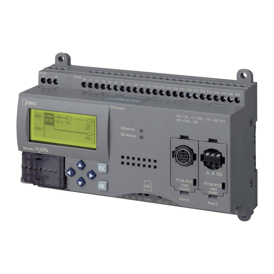
各部の名称 ■ FT1A-*12RA 名称 内容 ① 表示部 ② タッチパネル ③ 電源端子 RS232C、RS422/485 ④ シリアルインターフェイス(Port) コネクタ:端子台 9pin IEEE802.3u ⑤ イーサネットインターフェイス (Ethernet) 10BASE-T/100BASE-TX コネクタ:RJ-45 USB2.0 対応(デバイス) ⑥ USB インターフェイス(USB1) コネクタ:Mini-B USB1.1 対応(接続機器) ⑦ USB インターフェイス(USB2) コネクタ:Type A ⑧ 出力端子(Q0 ~ Q3) リレー出力(10A) ⑨... - Page 11 ■ FT1A-*14KA/14SA No. 名称 内容 ① 表示部 ② タッチパネル ③ 電源端子 RS232C、RS422/485 ④ シリアルインターフェイス(Port) コネクタ:端子台 9pin IEEE802.3u ⑤ イーサネットインターフェイス (Ethernet) 10BASE-T/100BASE-TX コネクタ:RJ-45 ⑥ USB インターフェイス(USB1) USB2.0対応 (デバイス) コネクタ Mini-B ⑦ USB インターフェイス(USB2) USB1.1対応 (接続機器) コネクタ : Type A ⑧ 出力端子(Q0 ~ Q3、AQ0 ~ AQ1) トランジスタ出力、アナログ出力...
- Page 12 外部インターフェイス 各インターフェイスへの配線を行う前には、必ず電源を切ってください。 より線および複数の電線を端子台に配線する場合は、必ず棒端子を使用してください。電 線が外れる恐れがあります。 4.1 シリアルインターフェイス(Port) インターフェイス仕様 RS232C、RS422/485 コネクタ 着脱式端子台 9pin RS232C: AWG16 ~ 28 適合電線 RS422/485: AWG16 ~ 28 シールド付きツイストペア 剥き線長さ 7mm(単線) AI 0.34-8 TQ(AWG22 用) AI 0.5-8 WH(AWG20 用) AI 0.75-8 GY(AWG18 用) 適合圧着端子 AI 1-8 RD(AWG18 用) AI 1.5-8 BK(AWG16 用)...
-
Page 13: 入出力端子
4.2 入出力端子 ■ FT1A-*12RA AWG16 ~ AWG22 適合電線 剥き線長さ 6.5mm, 被服径 φ3.4mm 以下(単線) AI 0.34-8 TQ(AWG22 用、電線 1 本用) AI 0.5-8 WH(AWG20 用、電線 1 本用) AI 0.75-8 GY(AWG18 用、電線 1 本用 ) 適合圧着端子 AI 1-10 RD(AWG18 用、電線 1 本用) AI 1.5-10 BK(AWG16 用、電線 1 本用) AI-TWIN 2×0.75-10 GY(AWG18 用、... - Page 14 ■ FT1A-*14KA + − 電源端子 1 SD 5 SG Port DC IN 9 RDB Tr OUT ANALOG OUT + − + − + + − アナログ電圧/ アナログ電圧/ 2線式 アナログ電圧/ 電流入力機器 電流入力機器 センサ 電流出力機器 − : ヒューズ : 負荷 ■ FT1A-*14SA + − 電源端子 1 SD ...
-
Page 15: 入力端子仕様
4.3 入力端子仕様 入力点数 定格入力電圧 DC24V 入力電圧範囲 DC0 ~ 28.8V 非破壊 入力誤接続の影響 (ただし、最大許容過負荷を超える高い電圧が印 加された場合には永久破壊の可能性あり) ● デジタル入力仕様 シンク(FT1A-*12RA/FT1A-*14SA) 入力形式 ソース(FT1A-*14KA) 入力点数 6 点 /1 コモン (端子番号 / コモン端子名) (I0 ~ I5/ 電源-端子) 4.4mA(シンク入力) 定格入力電流 5.2mA(ソース入力) 5.5kΩ(シンク入力) 入力インピーダンス 4.7kΩ(ソース入力) OFF → ON 2.5μs +ソフトフィルタ処理 入力遅延時間... - Page 16 サンプリング時間 2 ミリ秒以下 AD 変換時間 サンプリング間隔 2 ミリ秒以下 総合入力遅延時間 3ミリ秒+フィルタリング時間+スキャンタイム 25 ℃における フルスケールの ±3.0% 最大誤差 入力総合誤差 温度係数 フルスケールの ±0.04% / ℃ 総合誤差 フルスケールの ±5.0% 動作モード 自己スキャン 一般特性 変換方法 ΣΔ 型 状態表示 デバイスモニタ画面(LCD 表示) ノイズ試験時の最大瞬時誤差 フルスケールの ±5.0% ノイズイミュニティ向上のために推奨す シールド付きツイストペア るケーブルの種類 校正方法(誤差の調整) 不可...
- Page 17 サンプリング時間 2 ミリ秒以下 サンプリング間隔 2 ミリ秒以下 3ミリ秒+フィルタリング時間+スキャンタイム AD 変換時間 (電圧入力) 総合入力遅延時間 12 ミリ秒+フィルタリング時間+スキャンタイム (電流入力) 25 ℃における フルスケールの ±3.0% 最大誤差 入力総合誤差 温度係数 フルスケールの ±0.04% / ℃ 総合誤差 フルスケールの ±5.0% 動作モード 自己スキャン 一般特性 変換方法 状態表示 デバイスモニタ画面(LCD 表示) ノイズ試験時の最大瞬時誤差 フルスケールの ±5.0% ノイズイミュニティ向上のために推奨す シールド付きツイストペア るケーブルの種類...
- Page 18 ■ FT1A-*14KA ソース入力(I0 ~ I5) デジタル / アナログ共用(I6、I7) 24V DC 24V DC 24V DC 内 4.7kΩ 56kΩ 部 回 入力回路 47kΩ 路 入力回路 120Ω 22kΩ 130Ω 10kΩ ■ FT1A-*14SA シンク入力(I0 ~ I5) デジタル / アナログ共用(I6、I7) 24V DC 24V DC 内 内 56kΩ 部 4.3kΩ 部 回...
-
Page 19: 出力端子仕様
4.4 出力端子仕様 ● リレー出力仕様 ■ FT1A-*12RA 出力点数(端子番号) 4(Q0 ~ Q3) 出力形式 1a 接点 最大負荷電流 最小開閉負荷 10mA、DC5V(参考値) 初期接触抵抗 100mΩ 以下(1A、DC6V 時) 電気的寿命 10 万回以上(定格負荷 1800 回 / 時) 機械的寿命 2000 万回以上(無負荷 18000 回 / 時) 定格負荷電流 AC250V 10A、DC30V 10A 出力端子-内部回路 絶縁耐圧 AC2300V 5mA 1 分間... - Page 20 ● トランジスタ出力仕様 ■ FT1A-*14KA/14SA 出力点数(端子番号) 4(Q0 ~ Q3) シンク出力(FT1A-*14KA) 出力形式 ソース出力(FT1A-*14SA) 定格負荷電流 DC24V 使用入力電圧範囲 DC20.4 ~ 28.8V 最大負荷電流 0.3A 電圧降下(ON 電圧) 1V 以下(ON 時の COM- 出力端子間電圧) 最大突入電流 漏れ電流 0.1mA 以下 クランプ電圧 39V±1V 最大ランプ負荷 誘導負荷 L/R=10ms(DC28.8V、1Hz) 100mA 以下、DC24V 外部消費電流 シンク出力時:V(+) 端子供給電源 ソース出力時:COM(+) 端子供給電源...
- Page 21 ● アナログ出力仕様 ■ FT1A-*14KA/14SA 出力点数(端子番号) 2(AQ0 ~ AQ1) 出力形式 電圧 / 電流出力 DC0 ~ 10V(電圧出力) 出力範囲 DC4 ~ 20mA(電流出力) 2kΩ 以上(電圧出力) インピーダンス 500Ω 以下(電流出力) 出力負荷 負荷の種類 抵抗負荷 スキャンタイム 1 スキャン DA 変換 セットリング時間 1 ミリ秒以下 総合出力遅延時間 1ミリ秒 + 1スキャン デジタル分解能 0 ~...
- Page 22 仕様 ● 適用規格 UL508 安全規格 CSA C22.2 No.142 (c-UL) EMC 規格 ※1 IEC/EN 61131-2:2007 ※1 Touch を EMC 規格適合品として使用する場合、本体に接続する電源ケーブル、通信 ケーブルにフェライトコア(TDK 製 ZCAT3035-1330)を装着してください。 ノイズによる誤差発生の恐れがある場合、電源線、高圧線、負荷線等のノイズ源からは 離して設置ください。 または、 入出力ケーブルにフェライトコア (TDK 製 ZCAT3035- 1330)を装着ください。 ● 環境仕様 0 ~ 55 ℃: FT1A-M(モノクロ液晶機種) 使用周囲温度 ※2 -20 ~ 55 ℃: FT1A-C(カラー液晶機種) 氷結なきこと 使用周囲湿度...
- Page 23 ● 機械的仕様 5 ~ 8.4Hz 片振幅 3.5mm 振動 8.4 ~ 150Hz 定加速度 9.8m/s XYZ 各方向 10 回 (100 分間) (IEC61131-2 に適合) 衝撃 147m/s 11ms XYZ 各方向 5 回(IEC61131-2 に適合) ● 性能仕様 機種 FT1A-M(モノクロ液晶機種) FT1A-C(カラー液晶機種) 表示素子 STN モノクロ LCD TFT カラー LCD 2 色(黒...
- Page 24 ● ノイズ仕様 機種 FT1A-*12RA FT1A-*14KA/SA Class A : 10m 法 エミッション 40dBμV/m quasi-peak(30M ~ 230MHz) 47dBμV/m quasi-peak(230M ~ 1GHz) ±6kV (接触放電) 静電気放電 ±8kV (気中放電) 10V/m(80 ~ 1000 MHz) 3V/m(1.4 ~ 2.0 GHz) 放射電磁界 1V/m(2.0 ~ 2.7 GHz) 80% AM 変調(1kHz) ±2kV (電源端子、出力端子)...
-
Page 25: 外形寸法
外形寸法 ■ FT1A-*12RA 単位:mm <ケーブル付き外観図> 接続するケーブルの種類によって、掲載している寸法値は変わります。掲載している内容 は、設計時の目安にしてください。... - Page 26 ■ FT1A-*14KA/14SA 単位:mm 54.9 104.5 116.0 (58.9) <ケーブル付き外観図> 接続するケーブルの種類によって、掲載している寸法値は変わります。掲載している内容 は、設計時の目安にしてください。...
-
Page 27: 取付け
取付け 7.1 設置場所についての注意事項 Touch の性能及び安全の維持の観点から次のような場所への取付けは避けてください。 ・塵埃、塩分、鉄分などの多い場所 ・長時間油、薬品などがかかる場所 ・オイルミストが充満する場所 ・直射日光の当たる場所 ・強い紫外線を受ける場所 ・腐食性ガス、可燃性ガスの発生する場所 ・Touch に直接振動や衝撃の伝わる場所 ・急激な温度変化で結露が生じる場所 ・高電圧機器やアークが発生する機器(電磁開閉器、サーキットプロテクタなど)に近接 する場所 7.2 周囲温度についての注意事項 ・通風スペースを十分にとり、発熱量の大きい機器に近接して設置しないでください。 ・Touch と他の機器、構造物との間には、100mm 以上の空間を設けてください。 ・周囲温度が Touch の環境仕様欄で規定された温度を越える場合は、強制ファンやクー ラを設置してください。 ・Touch は垂直取付け自然空冷を前提にしています。 それ以外の姿勢で取り付ける場合に は強制空冷を行うか、周囲温度を下げて使用してください。 ● ディレーティングについて ■ FT1A-*12RA 45 ℃以上の使用周囲温度で使用の際は、下図に従って各出力端子の出力電流を軽減して ください。 【垂直取付け・横置き】 出力電流 使用周囲温度 45℃... - Page 28 〈注記〉 FT1A-*12RA は使用周囲温度が高温となった場合に、 バックライトの輝度を低減するこ とで製品内部の温度上昇を抑制します。 使用周囲温度、各出力端子の出力電流、輝度の関係は、おおよそ下図の通りとなります。 輝度 出力電流 10A 出力電流 5A 100% 出力電流 1A 出力端子不使用 使用周囲温度 35℃ 45℃ 50℃ 55℃ 製品個体によって掲載している値は変わります。掲載している内容は、設計時の目安にし てください。 ■ FT1A-*14KA/14SA 40 ℃以上の使用周囲温度で使用の際は、下図に従ってアナログ電流出力およびアナログ カートリッジの使用を制限してください。 電源電圧範囲 Touch アナログ出力 カートリッジ 使用周囲温度 電圧出力(FC6A-PK2AV)/ 20.4V ~ 24V 電圧 / 電流出力使用不可 電流出力(FC6A-PK2AW) 55 ℃...
-
Page 29: 取付け方法
7.3 取付け方法 ・パネル面に下記寸法で取付穴を空けてください。 単位:mm パネル圧 +1.0 +1.0 66.0 105.0 1.0 ~ 5.0 ・パネルへの取付けは付属の取付金具を用いて、規定締付トルク「0.3 ~ 0.35 N・m」で 上下面の合計 2ヶ所均一に締め付けてください。 ● 規定締付トルク範囲外で締め付けると本体ユニットに " ゆがみ " が発生し、表示部に " しわ " が発生したり、防水性能を損なう恐れがあります。 ● 取付金具がパネルに対して傾いていると、本製品がパネルから外れる恐れがあります。 ● パネルに取り付ける際には、パッキンに " ねじれ " が無いことをご確認ください。特に Touch を一度取り外した後、再度取り付ける場合にはご注意ください。防水性能が保 てなくなる恐れがあります。 ● パネル厚範囲であっても、パネルの材質、大きさによっては、防水性能が確保できなく なる恐れがあります。... -
Page 30: 取付け向きによる制限事項
7.4 取付け向きによる制限事項 Touch は横置きの垂直取付けを基本としています。それ以外の姿勢で取り付ける場合に は、使用周囲温度について制限があります。 使用周囲温度 取付け向き FT1A-M FT1A-C (モノクロ液晶機種) (カラー液晶機種) 横置き -20 ~ 55 ℃ 0 ~ 55 ℃ 氷結なきこと 縦置き(右回り) -20 ~ 50 ℃ 0 ~ 50 ℃ 氷結なきこと 縦置き(左回り) -20 ~ 55 ℃ 0 ~ 55 ℃ 氷結なきこと... -
Page 31: カートリッジ取付け方法
7.5 カートリッジ取付け方法 手順 1 マイナスドライバ 2 本を本体 2 箇所のドライバ差込口に差し込み、 カートリッジ カバーのツメ部を押し込んだ状態で、カートリッジカバーをまっすぐ取り外しま す。 ドライバ差込口 ドライバ差込口 カートリッジカバー 手順 2 カートリッジの方向に注意して、本体にまっすぐ取り付けます。 カートリッジ カートリッジを取り外す場合は、手順 1 の要領で作業を行ってください。 カートリッジは本体に対してまっすぐに脱着してください。傾いた状態で脱着すると、破 損や動作不良の原因になる場合があります。... -
Page 32: 電源端子への配線
配線 ● 配線作業は、必ず電源を切った状態で行ってください。 ● 全ての配線は、高電圧、大電流のケーブルと十分に離して最短距離で行ってください。 配線は各部の注意事項に従って作業を行ってください。 ● 動力機器、入出力機器などの電源とはそれぞれ系統を分けて配線してください。 ● 機器が安定動作するように機能接地端子を接地してください。 ● より線および複数の電線を端子台に配線する場合は、必ず棒端子を使用してください。 電線が外れる恐れがあります。 8.1 電源端子への配線 ・端子記号に対する信号内容は下表の通りです。 + 電源(+ 24V) - 電源(0V) 機能接地(FE) ・配線には適合したケーブルをご使用ください。また、各端子への配線は以下の推奨棒状 圧着端子(Phoenix Contact 製)をご使用ください。 AWG16 ~ AWG22 適合電線 剥き線長さ 7mm(単線) AI 0.34-8 TQ(AWG22 用) AI 0.5-8 WH(AWG20 用) AI 0.75-8 GY(AWG18 用)... -
Page 33: 外部機器と接続する場合の注意事項
8.2 外部機器と接続する場合の注意事項 Touch の電源は非絶縁となっています。外部機器との配線によっては、外部機器からの ノイズもしくは外来ノイズが Touch や外部機器の内部回路に悪影響を与える可能性があ ります。使用環境に合わせて以下のいずれかの対策を検討してください。 ・ノイズ源となる機器と Touch の接地を分ける ・ノイズ源となる機器から発生するノイズを正常に接地方向へ誘導できるように、接地用 電線を太く短くする ・ノイズ源となる外部機器と電源系統を分けることによって、ノイズ回り込み回路の形成 を防止する ・通信経路にアイソレータを接続することによって、ノイズ回り込み回路の形成を防止す る 8.3 パソコン接続時の注意事項 Touch をシリアルインターフェイス(Port)もしくは USB インターフェイスを介して パソコンに接続する場合、パソコンの機種および使用条件によっては、Touch やパソコ ンの故障が発生することがあります。故障を未然に防止するため、以下の点にご注意くだ さい。 ・電源プラグが三芯、もしくはアース線のあるパソコンを使用するとき アース付きのコンセントを使用するか、アース線を必ず接地してください。 ・電源プラグが二芯、かつアース線のないパソコンを使用するとき 以下の手順で Touch とパソコンを接続してください。 ①パソコンの電源プラグを AC コンセントから抜く。 ② Touch とパソコンを接続する。 ③パソコンの電源プラグを AC コンセントに挿入する。... -
Page 34: Usb ケーブル抜け防止ピンの取付けについて
USB ケーブル抜け防止ピンの取付けについて USB ケーブル抜け防止ピンを取り付けることで、USB インターフェイス(USB1、 USB2)に接続している USB ケーブルを抜けにくくすることができます。 USB ケーブルを差し込みます。 USB ケーブル抜け防止ピンの「先端部」を軽くたわませながら、USB ケーブル挿入口 の「上部の穴」2 箇所に「先端部」を挿入し取り付けます。 USB 結束バンドを USB ケーブルと USB ケーブル抜け防止ピンの 「結束部」 に巻きつけ て、しっかりと固定します。... - Page 35 〈注記〉 USB 結束バンドは、USB ケーブル抜け防止ピンの「結束部」との間にすき間なく、かつ 斜めにならないように巻きつけてください。...
-
Page 36: 保守・点検
保守・点検 Touch を最良の状態で使用していただくために、日常または、定期的にお手入れ、点検 を行ってください。なお、この時に分解、修理、改造等は行わないでください。 表面に付着した汚れ(油脂など)は中性洗剤、アルコール系溶剤をわ 表示部 ずかに含ませた柔らかい布などで拭き取ってください。シンナー、ア ンモニア、強酸系、強アルカリ系などの溶剤は使わないでください。 ねじの緩み、不完全な挿入、線材の切断などがないかを点検してくだ 端子台、コネクタ部 さい。 緩みがないかを確認し、緩みがある場合は規定締付トルクでの増締め 取付金具 を行ってください。 FT1A 形は、ユーザ様によるバックライトの交換はできません。バッ バックライト クライト切れの際は、弊社営業所までお問い合わせください。 タッチパネルによる操作精度は経年変化などによってズレを生じる タッチパネル ことがあります。タッチパネルの操作にズレがある場合には、タッチ パネルを調整してください。... -
Page 37: メンテナンス画面
10.1 メンテナンス画面 FT1A 形の電源投入後、 画面の左上隅を3秒間以上押します。 メンテナンス画面が表示さ れます。 メンテナンス画面(カラー液晶機種) メンテナンス画面(モノクロ液晶機種) ・メンテナンス画面を表示させるかどうかは WindO/I-NV3 で設定できます。詳しくは ユーザーズマニュアルを参照してください。 ・メンテナンス画面は、システムモードでは表示されません。 10.2 システムモード メンテナンス画面で [ システムモード ] を押すとシステムモードに入りトップページが表 示されます。 トップページ(カラー液晶機種) トップページ(モノクロ液晶機種) ・システムモードでは、初期設定や自己診断、データの初期化などを行うことができます。... -
Page 38: 輝度およびコントラスト調整
10.3 輝度およびコントラスト調整 輝度 / コントラスト調整画面にて Touch の表示の輝度やコントラストを調整できます。 必要に応じて最適な輝度およびコントラストに調整してください。 メンテナンス画面にある[輝度] (カラー液晶機種)または[輝度 / コントラスト] (モ ノクロ液晶機種)を押します。輝度 / コントラスト調整画面が表示されます。 カラー液晶機種 モノクロ液晶機種 [ << ] および [ >> ] を押して、輝度やコントラストを調整します。 カラー液晶機種 モノクロ液晶機種 右上部の [ × ](閉じる)を押して画面を閉じます。 システムモード時は、トップページの下部にある [ << ] および [ >> ] で輝度やコントラス トを調整できます。... -
Page 39: タッチパネル調整
10.4 タッチパネル調整 タッチパネルによる操作精度は経年変化などによってズレを生じることがあります。タッ チパネルの操作にズレがある場合には、次の手順に従いタッチパネルを調整します。 システムモードのトップページにある[Main Menu]を押します。メインメニュー画 面が表示されます。 トップページ(カラー液晶機種) トップページ(モノクロ液晶機種) [Init Set] 、 [Initialize] 、 [Touch PnlAdj]の順に押すと、確認画面に入り、 「Adjust Touch Panel Setting?」と表示されますので、 [Yes]を押します。タッチパネル調 整画面が表示されます。 表示される × マークの中心を押すと、マークの位置が次々に変わりますので、5ヶ所を 順に押してください。 〈注記〉 × マークを押すには、マークの中心を狙って押してください。 操作時の精度に影響が出る場合があります。 正常に認識されれば、 の確認画面に戻ります。 の手順で、× マークの中心から著しく離れた点を押した場合、認識エラーとなり、× マークは最初の位置に戻りますので、再度 の手順を繰り返してください。... - Page 41 Confirm that the delivered product is what you have ordered. Read this instruction sheet to make sure of correct operation. Make sure that the instruction sheet is kept by the end user. This manual is the instruction sheet of the SmartAXIS Series FT1A Touch. Unless otherwise specified, SmartAXIS refers to the SmartAXIS Series FT1A Touch.
- Page 42 ● Emergency and interlocking circuits must be configured outside of the Touch. Do not use the Touch’s internal touch switches for an emergency circuit. If the Touch failed, the external equipment connected to the Touch will no longer be protected and serious injury to operators and equipment damage may be caused.
- Page 43 ● Prevent metal fragments or wire chips from dropping inside the Touch housing. Ingress of such fragments and chips may cause fire hazard, damage, and malfunction. ● Use a power supply of the rated value. Using a wrong power supply may cause fire hazard.
- Page 44 Handling of Batteries and Devices with Built-in Batteries in EU Member States Note) The following symbol mark is for EU countries only and is according to the directive 2006/66/EC Article 20 information for end-users and Annex II. This symbol mark means that batteries and accumulators, at their end-of life, should be disposed of separately from your household waste.
- Page 45 Contents Packing ......................6 Type Number ....................7 Part Names ....................8 External Interfaces ..................10 Serial Interface (Port) ................. 10 I/O Terminals ..................11 Input Terminal Specifications ............. 13 Output Specifications ................. 17 Specifications .................... 20 Dimensions ....................23 Installation ....................
-
Page 46: Packing
Packing Before installing the Touch, make sure that the specifications of the product conform to your requirements, and that no parts are missing or damaged due to accidents during transportation. Name Pcs/pack Touch Unit Instruction Sheet [This manual] Mounting clips Power plug (Attached to the Touch) Communication I/F plug... -
Page 47: Type Number
Type Number LCD size /O configuration Bezel color Type No. Light gray FT1A-M12RA-W Digital sink in : 6pt Shared digital sink in / Analog in : 2pt Dark gray FT1A-M12RA-B Relay out : 4pt Silver FT1A-M12RA-S Digital source in : 6pt Light gray FT1A-M14KA-W Shared digital sink in / Analog in : 2pt... -
Page 48: Part Names
Part Names ■ FT1A-*12RA Name Description Display Touch Panel Power Supply Terminal RS232C, RS422/485 Serial Interface (Port) Connector : Terminal Block 9 pin EEE802.3u Ethernet Interface (Ethernet) 10BASE-T/100BASE-TX Connector : RJ-45 USB2.0 (Device) USB Interface (USB1) Connector : Mini-B USB1.1 (External device) USB Interface (USB2) Connector: TypeA Output Terminal (Q0 to Q3) - Page 49 ■ FT1A-*14KA/14SA Name Description Display Touch Panel Power Supply Terminal RS232C, RS422/485 Serial Interface (Port) Connector : Terminal Block 9 pin IEEE802.3u Ethernet Interface (Ethernet) 10BASE-T/100BASE-TX Connector : RJ-45 USB2.0 (Device) USB Interface (USB1) Connector : Mini-B USB1.1 (External device) USB Interface (USB2) Connector : Type A Output Terminal (Q0 to Q3, AQ0 to AQ1) Transistor output, analog output...
-
Page 50: External Interfaces
External Interfaces ● Make sure to turn off the power to the Touch before wiring each interface. ● Always use ferrules when wiring stranded wire and multiple wires to the terminal block. Otherwise there is a risk of wires becoming disconnected. 4.1 Serial Interface (Port) Interface Specification RS232C, RS422/485... -
Page 51: I/O Terminals
4.2 I/O Terminals ■ FT1A-*12RA AWG16 to AWG22 Applicable cable Stripped wire length 6 5 mm, coating diameter φ3.4 mm or lower (Solid wire) AI 0 34-8 TQ (For AWG22, For 1 wire) AI 0 5-8 WH (For AWG20, For 1 wire) AI 0.75-8 GY (For AWG18, For 1 wire) Recommended ferrule AI 1-10 RD (For AWG18, For 1 wire) - Page 52 ■ FT1A-*14KA Power supply terminal 1 SD 5 SG Port DC IN 9 RDB Tr OUT Analog OUT Analog vo tage/ Ana og vol age/ 2 wire Analog vo tage/ cu rent input device current nput device Senso cu rent input dev ce : Fuse : Load ■...
-
Page 53: Input Terminal Specifications
4.3 Input Terminal Specifications Input Points Rated Input Voltage 24V DC Input Voltage Range 0 to 28.8V DC No damage. Effect of Improper (If any input exceeding the rated value is applied, Input Connection permanent damage may be caused.) ● Digital Input Specifications Sink (FT1A-*12RA/14SA) Input Type Source (FT1A-*14KA) - Page 54 Sample Duration Time 2 msec max. Sample Repetition Time 2 msec max. AD Conversion Total Input System 3 msec + filtering time + scan time Transfer Time Maximum Error at 25°C ±3.0% of full scale Input Error Temperature Coefficient ±0.04% of full scale/°C Maximum Error ±5.0% of full scale Operating Mode...
- Page 55 Sample Duration Time 2 msec max. Sample Repetition Time 2 msec max. AD Conversion Total Input System 3 msec + filtering time + scan time (Voltage Input) Transfer Time 12 msec + filtering time + scan time (Current Input) Maximum Error at 25°C ±3.0% of full scale Input Error Temperature Coefficient ±0.04%/°C of full scale...
- Page 56 ■ FT1A-*14KA Source Input ( 0 to I5) Shared Digital/Analog Input ( 6, I7) 24V DC 24V DC 24V DC 4 7kΩ 56kΩ Input 47kΩ circuit Input circuit 120Ω 22kΩ 130Ω 10kΩ ■ FT1A-*14SA Sink Input (I0 to I5) Shared Digital/Analog Input ( 6, I7) 24V DC 24V DC 56kΩ...
-
Page 57: Output Specifications
4.4 Output Specifications ● Relay Output Specifications ■ FT1A-*12RA No. of Outputs (Terminal No.) 4 (Q0 to Q3) Output Type 1a contact Maximum Load Current Minimum Switching Load 10 mA/5V DC (reference value) Initial Contact Resistance 100 mΩ max. (1A, 6V DC) 100,000 operations min. - Page 58 ● Transistor Output Specifications ■ FT1A-*14KA/14SA No. of Outputs (Terminal No.) 4 (Q0 to Q3) Sink output (FT1A-*14KA) Output Type Source output (FT1A-*14SA) Rated Load 24V DC Operating Load Voltage 20.4 to 28.8V DC Range Maximum Load Current 0.3A Voltage Drop (ON voltage) 1V max.
- Page 59 ● Analog Output Specifications ■ FT1A-*14KA/14SA No. of Outputs (Terminal No.) 2 (AQ0 to AQ1) Output Type Voltage/current output 0 to 10 V (Voltage output) Output Range 4 to 20 mA (Current output) 2 kΩ min. (Voltage output) Impedance 500 Ω max. (Current output) Output Load Load Type Resistance load...
-
Page 60: Specifications
Specifications ● Applicable Standards UL508 Safety Standard CSA C22 2 No.142 (c-UL) EMC Standard*1 EC/EN 61131-2:2007 *1. When using the Touch as the EMC Standard Approved Products, attach a ferrite core (ZCAT3035- 1330 manufactured by TDK Corporation) to the power cables and the communication cables. If there a risk of an error occurring due to noise, install the product separated from sources of noise such as power lines, high voltage lines, and load lines. - Page 61 ● Construction Specifications 5 to 8.4Hz amplitude 3 5mm, 8.4 to 150Hz acceleration 9.8m/s Vibration Resistance 10 times on each of three mutually perpendicular axes (100 minutes) ( EC61131-2) 147m/s , 11ms (5 shocks on each of three mutually perpendicular axes) Shock Resistance ( EC61131-2) ●...
- Page 62 FT1A-*12RA: 300 g Weight (approx.) FT1A-*14KA/SA: 250 g *3. The backlight life refers to the time until the surface brightness reduces to a half after using continuously at room temperatures. *4. In high temperature environments battery life may be affected, so retention time may be reduced.
-
Page 63: Dimensions
Dimensions ■ FT1A-*12RA Unit: mm <Cable Attached Dimensions> Depending on the type of connection cable used the dimensions shown above will change. The dimensions given here are intended for reference only. - Page 64 ■ FT1A-*14KA/14SA Unit: mm 54.9 104.5 116.0 (58.9) <Cable Attached Dimensions> Depending on the type of connection cable used the dimensions shown above will change. The dimensions given here are intended for reference only.
-
Page 65: Installation
Installation 7.1 Operating Environment For designed performance and safety of the Touch, do not install the Touch in the following environments: • Where dust, briny air, or iron particles exist. • Where oil or chemical splashes for a long time. •... - Page 66 <Note> If operating the Touch in a high-temperature environment, reducing the brightness of the backlight can help to limit the temperature rise of internal components. The relationship between ambient temperature, the output current of each output terminal, and brightness is approximately as shown in the figure below. Brightness Output Current10A Output Current5A...
-
Page 67: Installation
Installation • Make a panel cut-out on the panel with the dimensions shown below. Unit: mm Panel Cut-out +1.0 +1.0 66.0 105 0 1.0 to 5 0 • The Touch has the mounting clip positions not only on the top and bottom side (0.3 to 0 35 N ·... -
Page 68: Orientation
7.4 Orientation The Touch is designed to install on a vertical landscape. If you install it with any other orientation, confirm the limitations about operating temperature. Operating Temperature Orientation FT1A-M FT1A-C (Monochrome LCD models) (Color LCD models) Landscape -20 to 55°C 0 to 55°C (No freezing) Portrait (Clockwise) -
Page 69: Attaching Cartridges
7.5 Attaching Cartridges Step 1 Insert two flat head screwdrivers into the screwdriver insertion slots in both locations of the unit, and while pushing the tabs of the cartridge cover, pull the cartridge cover directly upward to remove it. Screwdriver insertion slot Screwdriver insertion slot Cartridge cover... -
Page 70: Wiring
Wiring ● Turn off the power supply before wiring. ● Make the wiring as short as possible and run all wires as far away as possible from high-voltage and large-current cables. Follow all the procedures and precautions when wiring the Touch. ●... -
Page 71: Cautions When Connecting External Devices
8.2 Cautions when connecting external devices The Touch power supply is non-isolating. Interference or external noise from external devices due to wiring may cause adverse effects on the internal circuits of the Touch or external devices. To prevent such damage, choose a proper solution depending on your system setup. •... -
Page 72: Usb Cable Lock Pin Attachment
USB Cable Lock Pin Attachment When using the USB interface (USB1, USB2), attach the USB cable lock pin to prevent disconnecting the USB cable from the Touch. Insert the USB cable into the USB port. Strain the “Edge part” of the USB cable lock pin, and insert the “Edge part” to the 2 holes upper the USB port. - Page 73 <Note> Fasten the USB clamp band without the space between the clamp part and it, and the inclination.
-
Page 74: Maintenance And Inspection
The Touch backlight cannot be replaced by the customer. Backlight When the backlight needs to be replaced, contact IDEC. A gap may be caused in the operation accuracy of the touch panel by the secular distortion, etc. Touch Panel Adjust the touch panel according to the following procedure when there is a gap in the operation of the touch panel. -
Page 75: Maintenance Screen
10.1 Maintenance Screen Turn on the power to the Touch, then press and hold the upper-left corner of the screen for three seconds or longer. The Maintenance Screen appears on the screen. Maintenance Screen (Color LCD models) Maintenance Screen (Monochrome LCD models) •... -
Page 76: Adjusting The Brightness And Contrast
10.3 Adjusting the Brightness and Contrast The brightness and contrast of the Touch display can be adjusted on the Adjust Brightness/Contrast Screen. Adjust the brightness and contrast to the best condition as required. Press the Brightness (color LCD models) or Brightness/Contrast (monochrome LCD models) on the Maintenance Screen. -
Page 77: Adjusting The Touch Panel
10.4 Adjusting the Touch Panel A gap may be caused in the operation accuracy of the touch panel by the secular distortion, etc. Adjust the touch panel according to the following procedure when there is a gap in the operation of the touch panel. Press Main Menu on Top Page in System Mode. - Page 79 非常感谢您购买 IDEC 的产品。请确认订购的产品无误后,认真阅读本使用说明书的内容,正确 使用本产品。此外,请将本使用说明书由用户妥善保管。 本手册内容是针对 SmartAXIS 系列 FT1A Touch 和绘图软件 WindO/I-NV3 的说明。 如无特别指示,在本手册中,Touch 意指 SmartAXIS 系列 FT1A Touch。 Touch SmartAXIS FT1A-*12RA-* 型、FT1A-*14KA-* 型以及 FT1A-*14SA-* 型的总称。 安全上的重要注意事项 ● 在进行 Touch 的安装、接线、运行及维护工作之前,请仔细阅读本手册。 ● Touch 是在严格的品质管理体制下生产的,但是在万一有可能因本产品的故障而引起重大事 故或损害发生的用途上使用时,请确保本产品与适当的备用设备或安全保险设备一起使用。 ● 本手册使用以下两种警告标记来警告用户潜在的危险度。这些警告标记的含义如下所示。 如果不按警告中提示进行操作,可能会导致死亡或严重的人身伤害。 如果不按警告中的提示进行操作,可能会导致设备损坏或人身伤害。 ● Touch 不适用于对精确度和安全性有高要求的医疗仪器、原子能、铁路、航空及汽车等。...
- Page 80 ● 请注意在移动或运输过程中勿使 Touch 跌落,否则可能导致破损或引起故障。 ● 请在产品目录及使用手册所指定的环境中使用。在高温,高湿或结露以及有腐蚀性气体,或在 有较大冲击负载的环境中使用本产品时,有可能引起触电,火灾以及误动作的危险。 ● Touch 的污染等级为 2 级,请在污染等级为 2 级的环境下使用 (依据 IEC60664-1 规格) 。 ● 请按用户使用手册中的说明进行安装。 安装不正确可能导致产品跌落或损坏, 以及错误操作的 发生。 ● 在进行安装和接线工作时,请勿使接线废渣或钻孔金属废屑掉到 Touch 装置内部。否则会引 起火灾,故障或导致误动作。 ● 请与额定电源连接。否则会有引起火灾的危险。 ● Touch 的 DC 输入电源类型是 PS2 (依据 IEC/EN61131 规格) 。 ●...
- Page 81 ● Touch 前面的触摸屏为玻璃制,当受到冲击时有破碎的可能,在使用时一定要注意。 ● 模拟式触摸屏在检测特性上,当同时按下多个位置时,将所有按下位置的重心位置 (1 个位 置)作为按下位置判断。因此,多个位置同时按下不在动作保证之内。 ● 背景灯断线了时看不见画面, 但触摸屏仍处于激活状态。 如果误认为是背景灯熄灭状态而操作 触摸屏时,会被识别为错误的触摸屏操作。这种错误操作有可能导致损害,请注意。 ● 触摸屏的保护膜很容易划伤,请勿用工具等硬物按压或刮擦。 ● 在要求时钟精确度的系统中使用时,请定期调整时间。 ● 保存时如果超出了使用温度范围,时钟的精度会降低,再次使用前请重新校准时刻。 ● 显示部的 LCD 会因紫外线而老化,因此请避免在强紫外线下使用、保管。 ● 请勿进行分解、修理、改造等。否则会引起火灾、触电或故障。 ● Touch 的报废请作为工业废品处理。 ● 正在访问 USB 闪存时,请勿切断电源或拔出 USB 闪存。否则,可能导致 USB 闪存内数据的 损坏。数据发生损坏时,请对 USB 闪存进行格式化。...
- Page 82 欧盟及成员国区域内使用电池及内装电池设备的注意事项 注) 以下象征性标记仅在欧盟内的国家有效, 欧洲电池指令 2006/66/EC 第 20 条 “ 对最终用户的 信息 ” 及附件 II 中规定如下: 该象征性标记表示,在废弃电池及蓄电池时,必须与普通垃圾分类进行处理。 在上述象征性标记下标记有元素符号时,表示电池或者蓄电池中含有超标的重金属。浓度基准如 下所示。 Hg: 汞 (0.0005%), Cd: 镉 (0.002%), Pb: 铅 (0.004%) 电池及蓄电池,请遵从各国和地区的条例正确实施废弃。 关于船舶规格认证 本产品(FT1A-*14KA/SA, FT1A-*12RA(主体版本V120以后) )已取得以下船级社所颁发的认证。 • ABS ( 美国船级社 ),DNV GL( 挪威船级社 ),LR( 英国劳氏船级社 ),NK( 日本船级社 ) ( 关于使用范围、环境等,请另行联系我们。) •...
- Page 83 目录 包装目录 ........................6 型号构成 ........................7 各部分名称 ......................... 8 外部接口 ........................10 串行接口 (Port)..................10 输入输出端子 ....................11 输入端子规格 ....................13 输出端子规格 ....................17 规格 ........................... 20 外形尺寸 ........................23 安装 ........................... 25 有关设置场所的注意事项 ................25 有关环境温度的注意事项 ................25 安装方法...
-
Page 84: 包装目录
包装目录 在安装设备之前,确保了产品的规格符合您的要求,并且确认在运输过程中是否因为发生意外, 产品有丢失或破损的情况。 名称 数量 设备 使用说明 (本書) 安装配件 电源插头 (主体配套部件) 通信 I/F 插头 (主体配套部件) 防止 USB 电缆脱落用 pin USB 捆扎带... -
Page 85: 型号构成
型号构成 LCD 尺寸 I/O 结构 ( 灯罩 ) 主体色 型号 浅灰色 FT1A-M12RA-W Digital sink in : 6pt Dgital sink in / Analog in 兼用 : 2pt 深灰色 FT1A-M12RA-B Relay out : 4pt 亮银色 FT1A-M12RA-S Digital source in : 6pt 浅灰色 FT1A-M14KA-W Dgital sink in / Analog in 兼用... -
Page 86: 各部分名称
各部分名称 FT1A-*12RA ■ 名称 内容 ① 显示部 ② 触控屏 ③ 电源端子 RS232C、RS422/485 ④ 串行接口 (Port) 连接器:端子台 9pin IEEE802.3u ⑤ 以太网接口 (Ethernet) 10BASE-T/100BASE-TX 连接器:RJ-45 对应 USB2.0 (设备) ⑥ USB 接口 (USB1) 连接器:Mini-B 对应 USB2.0 (连接机器) ⑦ USB 接口 (USB2) 连接器:Mini-B ⑧ 输出端子... - Page 87 FT1A-*14KA/14SA ■ No. 名称 内容 ① 显示部 ② 触控屏 ③ 电源端子 RS232C、RS422/485 ④ 串行接口 (Port) 连接器:端子台 9pin IEEE802.3u ⑤ 以太网接口 (Ethernet) 10BASE-T/100BASE-TX 连接器:RJ-45 ⑥ USB 接口 (USB1) 对应 USB2.0 (设备)连接器:Mini-B ⑦ USB 接口 (USB2) 对应 USB1.1(连接机器)连接器:Type A ⑧ 输出端子 (Q0 ~ Q3, AQ0 ~ AQ1) 晶体管输出、模拟量输出...
-
Page 88: 外部接口
外部接口 ● 在对各接口进行配线之前,请务必切断电源。 ● 绞线及复数的电线连接到端子排时,请务必使用棒端子。电线可能会脱落。 4.1 串行接口 (Port) 接口规格 RS232C、RS485/422 连接器 可拆卸式端子台 9pin RS232C: AWG16 - AWG28 对应接线 RS422/485: AWG16 - AWG28 屏蔽双绞线 剥线长度 7mm (单线) AI 0.34-8 TQ (AWG22 用) AI 0.5-8 WH (AWG20 用) AI 0.75-8 GY (AWG18 用) 对应压接端子... -
Page 89: 输入输出端子
4.2 输入输出端子 FT1A-*12RA ■ AWG16 - AWG22 对应接线 剥线长度 6.5mm,绝缘径 φ3.4mm 以下 (单线) AI 0.34-8 TQ (AWG22 用,1 根电线用) AI 0.5-8 WH (AWG20 用,1 根电线用) AI 0.75-8 GY (AWG18 用,1 根电线用) 对应压接端子 AI 1-10 RD (AWG18 用,1 根电线用) AI 1.5-10 BK (AWG16 用,1 根电线用) AI-TWIN2×0.75-10 GY (AWG18 用,2 根电线用)... - Page 90 FT1A-*14KA ■ FT1A-*14SA ■...
-
Page 91: 输入端子规格
4.3 输入端子规格 输入点数 额定输入电压 24V DC 输入电压范围 0 - 28.8V DC 无损坏。 输入连接错误的后果 如果应用任何超过额定值的输入,则可能导致永 久性损坏。 ● 数字输入规格 漏型 (FT1A-*12RA/FT1A-*14SA) 输入类型 源型 (FT1A-*14KA) 输入点数 1 个通用行中有 6 个点 (端子编号 / 通用行名称) (I0 到 I5/ 电源 - 端子) 4.4mA (漏型输入) 额定输入电流 5.2mA (源型输入) 5.5KΩ... - Page 92 取样时间 2 毫秒以下 AD 变换 取样间隔 2 毫秒以下 总输入系统传送时间 3 毫秒 + 滤波时间 + 扫描时间 25 ℃时的最大误差 总范围的 ±3.0% 输入总误差 温度系数 总范围的 ±0.04%/ ℃ 总误差 总范围的 ±5.0% 工作模式 自扫描 一般特性 变换方法 逐次逼近 状态显示 “ 设备监控器 ” 屏幕 (LCD) 电子噪声测试时的最大瞬间偏差 总范围的 ±5.0% 推荐使用的电缆...
- Page 93 取样时间 2 毫秒以下 取样间隔 2 毫秒以下 AD 变换 3 毫秒 + 滤波时间 + 扫描时间 (电压输入) 总输入系统传送时间 12 毫秒 + 滤波时间 + 扫描时间 (电流输入) 25 ℃时的最大误差 总范围的 ±3.0% 输入总误差 温度系数 总范围的 ±0.04%/ ℃ 总误差 总范围的 ±5.0% 工作模式 自扫描 一般特性 变换方法 状态显示 “...
- Page 94 FT1A-*14KA ■ 源型输入 (I0 - I5) 共用数字 / 模拟量 (I6、I7) FT1A-*14SA ■ 漏型输入 (I0 - I5) 共用数字 / 模拟量 (I6、I7) ● 操作范围 漏型输入 (I0 - I5) 源型输入 (I6、I7) 共用数字 / 模拟量 (I6、I7)...
-
Page 95: 输出端子规格
输出端子规格 ● 继电器输出规格 FT1A-*12RA ■ 输出点数 (端子编号) 4 (Q0 - Q3) 输出类型 1a 接点 最大负载电流 最小切换负载 10mA、5V DC (参考值) 初始接触电阻 100mΩ 以下 (1A、6V DC) 电气性使用寿命 100,000 次以上操作 (额定负载 1,800 次操作 / 小时) 机械性使用寿命 20,000,000 次以上操作 (无负载 18,000 次操作 / 小时) 额定负载电流... - Page 96 ● 晶体管输出规格 FT1A-*14KA/14SA ■ 输出点数 (端子编号) 4 (Q0 - Q3) 漏型输出 (FT1A-*14KA) 输出类型 源型输出 (FT1A-*14SA) 额定负载电流 24V DC 使用输入电压范围 20.4 - 28.8V DC 最大负载电流 0.3A 电压下降 (ON 电压) 1V 以下 (ON 时的 COM- 输出端子间电压) 最大浪涌电流 漏电流 0.1mA 以下 钳位电压 39V±1V 最大指示灯负载...
- Page 97 ● 模拟量输出规格 FT1A-*14KA/14SA ■ 输出点数 (端子编号) 2 (AQ0 - AQ1) 输出类型 电压 / 电流输出 DC0 - 10V (电压输出) 输出范围 4 - 20mA (电流输出) 2kΩ 以上 (电压输出) 输出阻抗 500Ω 以下 (电流输出) 输出负载 负载的种类 电阻负载 扫描时间 1 次扫描 DA 变换 置位时间 1 毫秒以下 总输出系统传送时间...
- Page 98 规格 ● 对应标准 UL508 安全标准 *1 CSA C22.2 No.142 (c-UL) EMC 标准 IEC/EN 61131-2:2007 *1. 如果作为 EMC 标准认定系统使用 Touch,请为连接在实体的电力电缆和通信电缆安装铁氧体 磁心 (TDK 公司制造的 ZCAT3035-1330) 可能因干扰产生误差时,请远离电源线、高压线、负载线等干扰源进行安装。此外,请在输入 / 输出电缆上安装铁氧体磁心 (TDK 公司制造的 ZCAT3035-1330) 。 ● 环境规格 0 - 55 ℃:FT1A-M (黑白液晶型号) 使用环境温度 *2 -20 - 55 ℃:FT1A-C (彩色液晶型号) (无冻结) 使用环境湿度...
- Page 99 ● 机械规格 5 - 8.4Hz 单振幅 3.5mm 耐振动 8.4 - 150Hz 恒加速度 9.8m/s XYZ 各方向 10 次 (100 分钟) (符合 IEC61131-2) 抗冲击性 147m/s 11ms XYZ 各方向 5 次 (符合 IEC61131-2) ● 性能规格 产品系列 FT1A-M (黑白液晶型号) FT1A-C (彩色液晶型号) STN 黑白 LCD TFT 彩色...
- Page 100 ● 噪音规格 产品系列 FT1A-*12RA FT1A-*14KA/SA Class A : 10m 法 电磁场强度 40dBμV/m quasi-peak (30M - 230MHz) 47dBμV/m quasi-peak (230M - 1GHz) ±6kV (接触放电) 静电放电 ±8kV (空气放电) 10V/m (80 - 1000 MHz) 3V/m (1.4 - 2.0 GHz) 放射电磁场 1V/m (2.0 - 2.7 GHz) 80% AM 调制...
-
Page 101: 外形尺寸
外形尺寸 FT1A-*12RA ■ 单位:mm <电缆连接外视图> 要连接的电缆种类不同,所记载的尺寸值有所差异。记载的内容,请作为设计时的目标值加 以参考。... - Page 102 FT1A-*14KA/14SA ■ 单位:mm 54.9 104.5 116.0 (58.9) <电缆连接外视图> 要连接的电缆种类不同,所记载的尺寸值有所差异。记载的内容,请作为设计时的目标值加 以参考。...
-
Page 103: 有关设置场所的注意事项
安装 7.1 有关设置场所的注意事项 从维持 Touch 的性能及安全角度考虑,请避免在以下场所安装。 • 多灰尘、盐分、铁粉等的场所 • 长时间悬挂油、药品等的场所 • 油雾充满的场所 • 阳光直接照射的场所 • 受强紫外线照射的场所 • 发生腐蚀性气体、可燃性气体的场所 • 会直接将振动或冲击传递给 Touch 的场所 • 温度变化急剧、产生结露的场所 • 与高压设备和发生电弧的设备 ( 电磁接触器、电路保护器等 ) 邻近的场所 7.2 有关环境温度的注意事项 • 请留有充足的通风空间,避免在发热量大的设备附近进行设置。 • Touch 与其他设备、构建物之间,请留出 100mm 以上的空间。 • 环境温度超过 Touch 中环境规格栏的额定温度时,请设置换气扇或冷却装置。 •... - Page 104 <备注> Touch 在操作环境温度升高的情况下,通过降低背光灯亮度来抑制产品内部温度上升。 操作环境温度、各输出端子的输出电流、亮度的关系大致如下图。 100% 35℃ 45℃ 50℃ 55℃ 刊载数值因产品个体而变化。刊载内容请作为设计时的目标值加以参考。 FT1A-*14KA/14SA ■ 在 40 ℃或以上的操作环境温度下使用时,请按下图所示限制使用模拟电流输出以及模拟盒。 电压使用范围 Touch 模拟输出 盒 使用环境温度 不可使用 不可使用电压 / 电压输出 (FC6A-PK2AV)/ 55 ℃ DC20.4 - 24V 电流输出 电流输出 (FC6A-PK2AW) 不可使用 不可使用电流输出 电压输出 (FC6A-PK2AV)/ 50 ℃ DC20.4 - 28.8V 电流输出...
-
Page 105: 安装方法
7.3 安装方法 • 请在面板上按下列尺寸留出安装孔。 単位:mm 面板厚度 +1.0 +1.0 66.0 105.0 1.0 - 5.0 • 请用附带的安装支架将显示器安装到面板, 并按额定拧紧扭矩 “0.3 - 0.35 N•m” 均匀锁紧 2 个部位。 ● 如果以规定范围以外的拧紧扭矩进行锁紧, 可能造成主体单元的 “ 分布不匀 ” 或者显示部的 " 褶皱 ",从而损害防水性能。 ● 如果安装配件相对面板出现倾斜,则有可能本产品从面板上脱落。 ● 安装在面板上时,请检查密封垫圈有无 “ 扭曲 ”。特别是一度拆下 Touch 后再次安装时,请 务必注意。否则不能保证防水性能。... -
Page 106: 安装方位的限制事项
7.4 安装方位的限制事项 Touch 一般采用水平放置的垂直安装方式。如果以其他状态安装,对使用环境温度有限制。 使用环境温度 安装方位 FT1A-M FT1A-C (黑白液晶型号) (彩色液晶型号) 水平放置 -20 ~ 55 ℃ 0 - 55 ℃ (无冻结) 直立 (右旋转) -20 ~ 50 ℃ 0 - 50 ℃ (无冻结) 直立 (左旋转) -20 ~ 55 ℃ 0 - 55 ℃ (无冻结)... -
Page 107: 盒的安装方法
7.5 盒的安装方法 步骤 1 将 2 个一字螺丝刀插入本体 2 处的螺丝刀插入口,在按压住盒盖卡扣部的状态下,笔直 卸下盒盖。 步骤 2 注意盒的方向,笔直安装到本体。 卸下盒时,请按步骤 1 的要领进行作业。 请笔直装卸盒。若在倾斜的状态下进行装卸,可能会导致破损或操作不良。... -
Page 108: 电源端子上的配线
配线 ● 请务必在切断电源的状态下进行配线作业。 ● 所有的配线请充分避开高电压、大电流的电缆,以最短距离进行。请遵从各部分的注意事项, 进行配线作业。 ● 请与动力设备、输入输出设备等电源分别按系统进行配线。 ● 为了使设备能稳定地动作,请将功能接地端子接地。 ● 绞线及复数的电线连接到端子排时,请务必使用棒端子。电线可能会脱落。 8.1 电源端子上的配线 • 下表为对应端子编码的信号内容。. + 电源 (+ 24V) - 电源 (0V) 功能接地 (FE) • 配线请使用适合的电缆。同时,各端子上的配线,请使用以下推荐的棒状压接端子 (Phoenix Contact 制 ) AWG16 - AGW22 对应接线 剥线长度 7mm (单线) AI 0.34-8 TQ (AWG22 用) AI 0.5-8 WH (AWG20 用)... -
Page 109: 与外部设备连接时的注意事项
8.2 与外部设备连接时的注意事项 Touch 的电源非绝缘。由于与外部设备连接的不同,来自外部设备的噪声或外来噪声可能对会 Touch 或外部设备的内部线路造成不良影响。请根据使用环境研究采用以下某种对策。 • 将构成噪音源的设备和 Touch 的接地相分离。 • 为了能够将构成噪音源的设备产生的噪音正常地导向接地方向,加粗、缩短接地用电线。 • 通过将噪音源外部设备与电源系统加以分隔,防止噪音环绕电路的形成。 • 通过在通信路径上连接隔离器,防止噪音环绕电路的形成。 8.3 连接计算机时的注意事项 通过串行接口(Port)或者 USB 接口将 Touch 与计算机连接时,由于计算机机型及使用条件的 不同,有时会发生 Touch 或计算机的故障。为防故障于未然,请注意以下几点。 • 使用电源插头为三芯,或有地线的计算机时, 请务必使用带接地的插座,或者将地线接地。 • 使用电源插头为二芯,且无地线的计算机时, 请按以下的步骤连接 Touch 与计算机。 ①从 AC 插座中拔下计算机的电源插头。 ②连接 Touch 与计算机。 ③将计算机的电源插头插入... -
Page 110: 关于防止 Usb 电缆脱落用 Pin 的安装
关于防止 USB 电缆脱落用 pin 的安装 防止 USB 电缆在安装时脱落,用 pin 能使 USB 接口 (USB1、USB2)和 USB 电缆连接一起的 时候不易脱落。 插入 USB 电缆。 一边轻轻地弯曲防止USB 电缆脱落用pin 的“尖端部”, 一边将“尖端部”插入USB 电缆插 入口的 “ 上部孔 ” 安装。 将 USB 捆扎带缠绕在 USB 电缆和防止 USB 电缆脱落用 pin 的 “ 捆扎部 ”,牢靠地固定。... - Page 111 <备注> 缠绕 USB 捆扎带时,与防止 USB 电缆脱落用 pin 的 “ 捆扎部 ” 之间应无缝隙且避免倾斜。...
-
Page 112: 维护和检查
维护和检查 为使在最佳状态下使用 Touch,请日常定期地进行维修和检查。并且,请勿进行分解、修理和改 造等。 表面附着污物 ( 油脂等 ) 时,请用少许蘸有中性洗涤剂、酒精溶剂的柔 显示部 软布等擦拭干净。请勿使用稀释剂、氨水、强酸类、强碱类等溶剂。 端子台、连接器部 请检查有无螺丝松动、不完全插入和线材切断等情况。 安装支架 请检查有无松动,有松动时,请按规定拧紧扭矩拧紧。 背景灯 Touch 用户不能更换背景灯。背景灯烧毁时,请向本公司营业所咨询。 触控屏的操作精度会因老化等而产生差异。 如果触控屏的操作有差异 触控屏 时,请调整触控屏。... -
Page 113: 维护画面
10.1 维护画面 请接通 Touch 的电源,在画面左上角的触控屏上持续按 3 秒钟以上。显示维护画面。 维护画面 (彩色液晶型号) 维护画面 (黑白液晶型号) • 可利用 WindO/I-NV3 设定是否显示维护画面。详情请参阅用户手册。 • 在系统模式下不显示维护画面。 10.2 系统模式 在维护画面中按 “ 系统模式 ”,则进入系统模式显示首页。 首页 (彩色液晶型号) 首页 (黑白液晶型号) • 在系统模式下,可进行初始设定、自我诊断及数据的初始化等。... -
Page 114: 亮度及对比度调整
10.3 亮度及对比度调整 可在亮度 / 对比度调整画面上调整 Touch 的显示亮度与对比度。请根据需要调整到最适合的亮 度及对比度。 在维护画面中,按下 “Brightness”(彩色液晶型号)或者 “Brightness/Contrast”(黑白 液晶型号) 。显示亮度 / 对比度调整画面。 彩色液晶型号 黑白液晶型号 按下 “ << ” 或者 “ >> ”,调节到舒适的亮度。 彩色液晶型号 黑白液晶型号 按右上方的 “ × ” (关闭)则画面关闭。 在系统模式时,请用位于首页下方的 “ << ” 及 “ >> ” 调整到最适合的亮度与对比度。 首页... -
Page 115: 触控屏调整
10.4 触控屏调整 触控屏的操作精度会因老化等而产生差异。如果触控屏的操作有差异时, 请按以下步骤调整触控 屏。 请按位于系统模式首页的 “Main Menu”。显示主菜单画面。. 首页 (彩色液晶型号) 首页 (黑白液晶型号) 依次按 “Initial Setting”(初始设定) 、“Initialize” (初始化) 、“Touch PnlAdj”(触 摸屏调整), 则进入确认画面, 显示“Adjust Touch Panel Setting?” (是否调整触摸屏?) , 按 “Yes” (是) 。显示触控屏调整画面。 按显示中的 × 的中心,则符号的位置逐次发生变化,请依次按 5 个部位。 <备注> 在按 × 时,请尽量瞄准符号的中心按下。这将确保触摸面板的操作精度。 如果能正常识别,... - Page 118 (土・日曜日、祝日および弊社休日を除く) 【技術問い合わせ窓口】 0120-992-336 ■携帯電話・PHS の場合は 050-8882-5843 http://www.idec.com 合格证 本产品经检验合格 可编程控制器 对应标准 : IEC/EN61131-2 销售者 IDEC 株式会社 工厂地址 深圳市龙华新区观澜街道星花社区品顺路 5 号 (This description is based on Law of China on Product Quality.) 本社 〒 532-0004 大阪市淀川区西宮原 2-6-64 TEL+81-06-6398-2500 关于使用说明书有不明白的地方,请联络以下技术咨询窗口 咨询时间:9:00~12:00/13:00~17:00 (周六、日及公休日、我司休息日除外)...
Need help?
Do you have a question about the SmartAXIS FT1A Series and is the answer not in the manual?
Questions and answers