IDEC SmartAXIS Touch FT1A Series User Manual
Hide thumbs
Also See for SmartAXIS Touch FT1A Series:
- User manual (393 pages) ,
- Instruction sheet (118 pages) ,
- User manual (393 pages)
Table of Contents
Advertisement
Quick Links
Advertisement
Table of Contents

Related Manuals for IDEC SmartAXIS Touch FT1A Series


Summary of Contents for IDEC SmartAXIS Touch FT1A Series
- Page 1 FT9Y-B1390 (4) FT1A Series SmartAXIS Touch User’s Manual...
-
Page 2: Safety Precautions
In addition, we ask that you contact your IDEC sales office to confirm the safety of the application according to the specifications and similar documents. - Page 3 SAFETY PRECAUTIONS • Prevent the SmartAXIS FT1A-*12RA-*, FT1A-*14KA-* and FT1A-*14SA-* from falling while moving or transporting, otherwise damage or malfunction of the SmartAXIS FT1A-*12RA-*, FT1A-*14KA-* and FT1A-*14SA-* will result. • Use the product within the environmental limits given in the catalog and manual. Use of the product in high- temperature or high-humidity environments, or in locations where it is exposed to condensation, corrosive gas or large shock loads can create the risk of electrocution and fire.
-
Page 4: Revision History
IDEC Corporation. Unauthorized duplication, reproduction, sales, transfers, or leasing is prohibited. • The contents of this manual and the WindO/I-NV3 and WindLDR applications are subject to change without notice. • IDEC Corporation accepts no responsibility for circumstances arising from the use of this manual or the WindO/I-NV3 and WindLDR applications. - Page 5 Preface Preface This user’s manual describes entire functions, specifications, installation, and operation basics of the SmartAXIS. Also included are powerful communications of the SmartAXIS and troubleshooting procedures. This manual describes SmartAXIS Touch (SmartAXIS FT1A-*12RA-*, FT1A-*14KA-* and FT1A-*14SA-*) and WindO/I-NV3 software. The information includes drawing tools, setup procedures, and how to configure all Touch operator interfaces.
- Page 6 Symbols Used in this Document Symbols Used in this Document This manual uses the following symbols to facilitate description. Symbols …… Useful information relating to a function Information that requires special attention. Failure to operate the product in accordance with ……...
- Page 7 Abbreviations, Generic Terms, and Terminology Used in this Manual Abbreviations, Generic Terms, and Terminology Used in this Manual Item Description SmartAXIS Another name for the SmartAXIS FT1A Series. Touch The generic term for the SmartAXIS FT1A-*12RA-*, FT1A-*14KA-* and FT1A-*14SA-*. Touch (relay output type) The generic term for the SmartAXIS FT1A-*12RA-*.
- Page 8 Abbreviations, Generic Terms, and Terminology Used in this Manual Item Description External memory For the Touch, a USB flash drive. Screens that are loaded on to the Base Screen, including Popup Screen and Device Window Monitor. Drawings Define as as non functional content (i.e. shape, picture, text). Parts Define as functional content (i.e.
-
Page 9: Table Of Contents
Contents Contents SAFETY PRECAUTIONS ................Preface-1 Revision history ................... Preface-3 Caution ....................... Preface-3 Trademarks ....................Preface-3 Regarding laws and compatible standards ............. Preface-3 Preface ....................... Preface-4 Symbols Used in this Document ..............Preface-5 Abbreviations, Generic Terms, and Terminology Used in this Manual ....Preface-6 Chapter 1 General Information for SmartAXIS About the SmartAXIS .................... - Page 10 Contents Printing Project Data ..................3-7 Comparing Project Data .................3-13 Changing Project Settings ................3-14 Closing Project Data ..................3-17 Project Settings Configuration Procedure ...............3-18 Project Settings Dialog Box...................3-19 System Tab ....................3-19 Communication Interface Tab.................3-27 Communication Driver Tab ................3-32 Communication Driver Network Tab ..............3-34 Communication Driver Extension Tab ..............3-36 O/I Link Tab....................3-37 User Communication Tab ................3-38...
- Page 11 Contents Deleting Screens ...................4-10 Reusing Screens.................... 4-12 Base Screen ....................... 4-14 Base Screen Settings ..................4-14 Displaying Layered Base Screens..............4-18 Operating When Drawing Objects and Parts Overlap........4-20 Popup Screen ..................... 4-22 Popup Screen Settings...................4-22 Popup Screen Configuration ................4-25 Standard Keypad Popup Screen..............4-26 Screen Restrictions .....................
- Page 12 Contents Text Configuration Procedure .................6-25 Properties of Text dialog box ................6-26 Chapter 7 Buttons Bit Button ......................7-1 How the Bit Button is Used ................7-1 Bit Button Configuration Procedure ..............7-3 Properties of Bit Button Dialog Box ..............7-4 Word Button......................7-17 How the Word Button is Used.................7-17 Word Button Configuration Procedure .............7-20 Properties of Word Button Dialog Box .............7-21...
- Page 13 Contents Chapter 9 Data Displays Numerical Input....................9-1 How the Numerical Input is Used ..............9-1 Numerical Input Configuration Procedure ............9-2 Properties of Numerical Input Dialog Box ............9-3 How to Enter Values ..................9-21 Advanced Usage ...................9-22 Character Input ....................9-23 How the Character Input is Used ..............
- Page 14 Contents Line Chart Configuration Procedure............... 10-20 Properties of Line Chart Dialog Box............... 10-21 Pie Chart......................10-39 How the Pie Chart is Used................10-39 Pie Chart Configuration Procedure ..............10-40 Properties of Pie Chart Dialog Box ..............10-41 Meter........................ 10-48 How the Meter is Used................. 10-48 Meter Configuration Procedure ..............
- Page 15 Contents Chapter 13 Alarm Log Function Overview......................13-1 How the Alarm Log Function is Used............... 13-1 Alarm States ....................13-3 Sampling Data ....................13-4 Data Configuration ..................13-5 Saving and Deleting Data ................13-7 Using Data and Detected Alarms ..............13-9 Alarm Log Function Configuration Procedure............13-10 Configuring the Devices to Monitor and the Alarm Detection Condition....
- Page 16 Contents Chapter 16 Data Storage Area Overview ......................16-1 What is the Data Storage Area?..............16-1 Data Storage Area ..................16-2 Data Storage Area Configuration Procedure ............16-3 Data Storage Area Management Dialog Box............16-4 Data Storage Area Management Dialog Box ............16-4 Chapter 17 Preventive Maintenance Function Overview ......................17-1 How the Preventive Maintenance Function is Used ...........17-1 Counting the Operation Time and Operation Count ..........17-2...
- Page 17 Contents Text Group Settings Dialog Box ..............19-15 Chapter 20 Script About the Script Function ..................20-1 Overview of the Script Function..............20-1 Types and Trigger Conditions of the Script for HMI Function ......20-2 Data Type of the Script .................. 20-3 Script Error of HMI Function................20-4 Editing and Management of the Script ..............
- Page 18 Contents Overview ......................22-3 O/I Link Communication Settings..............22-3 DM Link Communication..................22-4 Overview ......................22-4 DM Link Communication Settings..............22-5 No External Devices .....................22-6 Overview ......................22-6 No External devices Settings ................22-6 User Communication....................22-7 Overview ......................22-7 User Communication Settings Procedure ............22-8 Protocol Manager ..................22-21 Example of User Communication Settings............
- Page 19 Contents Chapter 25 Data Transfer Function Project Transfer Function..................25-1 How the Project Transfer Function is Used ............25-1 Project Data Transfer Procedures..............25-1 Converting Project Data for Transfer ............... 25-2 Using Key Buttons, Multi-Buttons, or Multi-Commands to Transfer Project Data..25-5 Precautions....................
- Page 20 Contents Chapter 29 SmartAXIS Specifications Touch .........................29-1 Packing Contents...................29-1 Type Number ....................29-2 Part Names ....................29-3 External Interfaces ..................29-5 Specifications ....................29-14 Dimensions ....................29-16 Installation ....................29-18 Attaching Cartridges (FT1A-*14KA/SA only) ..........29-22 Wiring ......................29-23 1.10 USB Cable Lock Pin Attachment..............29-24 1.11 Maintenance and Inspection.................
- Page 21 Contents FBD Program Limitation .................A-15 USB Driver ......................A-18 Installing the USB Driver................A-18 Checking the USB Driver................A-28 Index Preface SmartAXIS Touch User's Manual...
- Page 22 Contents Preface SmartAXIS Touch User's Manual...
-
Page 23: General Information For Smartaxis
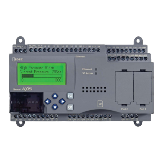
General Information for SmartAXIS Chapter 1 This chapter describes SmartAXIS functions and system configuration examples. About the SmartAXIS The SmartAXIS is available in three types: the SmartAXIS Touch, the SmartAXIS Pro, and the SmartAXIS Lite. The SmartAXIS Touch is equipped with the HMI functions of an operator interface and PLC control functions. In addition to the functions of control and communication as a PLC, the SmartAXIS Pro is equipped with an LCD and operation buttons on the front of the module. -
Page 24: Features For The Touch
1 About the SmartAXIS 1.2 Features for the Touch This section describes the features of the Touch. The Touch is high-performance programmable controller in a compact package and is equipped with high speed counters. The Touch enables you to build optimum systems to automate factories or control production lines. Powerful display functions ■... -
Page 25: Special Functions For The Touch
1 About the SmartAXIS 1.3 Special Functions for the Touch This section describes the functions of the Touch. I/O Related Functions ● Catch Input ■ The catch input allows it to receive short input pulses from sensors without regard to the scan time. A maximum of four catch inputs can be used. - Page 26 1 About the SmartAXIS Pulse I/O Functions ● High-speed Counter ■ This function counts high-speed pulse inputs that cannot be measured in normal ladder program or FBD program processing. Use this function for applications such as positioning control with a rotary encoder or motor control. The Touch can use singlephase high-speed counters and two-phase high-speed counters.
-
Page 27: About The Windo/I-Nv3
2 About the WindO/I-NV3 About the WindO/I-NV3 WindO/I-NV3 is software that is exclusively designed for operation with the Touch, for specifying settings and creating screens and the ladder program or FBD program. The set of data made up of settings, created screens, and ladder program or FBD program is called a project. -
Page 28: Operating Modes
3 Operating Modes Operating Modes The Touch includes multiple modes, so you switch between modes as and when necessary. These modes are called operating modes. The functions and the operations and conditions for switching are as follows. Conditions required for Mode Functions switching to the mode... -
Page 29: Flow From Screen And Ladder Program Or Fbd Program Creation To Run Operation
4 Flow from Screen and Ladder Program or FBD Program Creation to Run Operation Flow from Screen and Ladder Program or FBD Program Creation to Run Operation The following flowchart describes the sequence of step from the screen and the ladder program or FBD program creation for the Touch to the Run operation. - Page 30 4 Flow from Screen and Ladder Program or FBD Program Creation to Run Operation SmartAXIS Touch User's Manual...
-
Page 31: Windo/I-Nv3 Basic Operations
WindO/I-NV3 Basic Operations Chapter 2 This chapter describes the minimum system requirements for WindO/I-NV3, how to start and exit it, and the configuration of its screens and menus. WindO/I-NV3 Specifications 1.1 Minimum System Requirements The table below shows the minimum system requirements for WindO/I-NV3. Item Description Windows 7 (64-bit and 32-bit versions),... -
Page 32: Available Data
1 WindO/I-NV3 Specifications 1.2 Available Data Data types ● Data type is the format of the data related to the minimum and maximum values of data that can be processed by a part and handling of negative and real numbers. Data types and data ranges that can be used on the Touch and WindO/I-NV3 are listed below. - Page 33 1 WindO/I-NV3 Specifications Data type Data handling Data is handled as a 32-bit floating-point real number. The number of significant digits is 6 digits. The floating-point type data format conforms to the IEEE (The Institute of Electrical and Electronics Engineers) standard for the single precision storage format as explained next.
- Page 34 1 WindO/I-NV3 Specifications Data type Storing 1234 (hex) in LDR10 Storing F765 (hex) in LDR10 LDR10 LDR10 0001001000110100 1111011101100101 BCD4 234 (Hex) − 765 (Hex) The sign is F (hex), so the binary-coded decimal The sign is 1 (hex), so the binary-coded decimal value of the negative number 765 (hex), value of the positive number 234 (hex), handled as -765 (dec).
- Page 35 1 WindO/I-NV3 Specifications Indirect Read and Indirect Write Settings ● The indirect specification of a device address means to add a value (indirect value) to the address of the configured device and use that address as the actual read source or write destination. You can change the read source or write destination address just by changing this indirect value.
-
Page 36: Available Text
1 WindO/I-NV3 Specifications 1.3 Available Text Font ● Supported Languages The Touch can display multiple fonts by installing them. In addition to the fonts installed on the Touch, all Windows fonts displayed on your computer can be used on the display. Font Description Fonts to be pre-loaded on the Touch. - Page 37 1 WindO/I-NV3 Specifications Installed Fonts in the Touch Font Name Code System Language JIS 8-bit code Japanese JIS level-1 and Japanese Standard level-2 kanji sets Fonts Icelandic, Irish, Italian, English, Dutch, Swedish, Spanish, Danish, English ISO 8859-1 (Latin1) German, Norwegian, Portuguese, Finnish, Faeroese, French Japanese large * Install this font to achieve a sharper display of enlarged JIS font...
- Page 38 1 WindO/I-NV3 Specifications Available Fonts for Parts Parts Description Windows Font Touch installed Font Bit Button Word Button Goto Screen Button Buttons Key Button Keypad Selector Switch Pilot Lamp Lamps Multi-State Lamp Numerical Input Character Input *2*3 Message Display Message Switching Display Data Displays Alarm List Display Alarm Log Display...
- Page 39 1 WindO/I-NV3 Specifications Font Size Font Name Code System Size Japanese large font (first standard) JIS level-1 kanji set 477KB Japanese large font (second standard) JIS level-2 kanji set 424KB Chinese GB2312 238KB Korean KSC5601 109KB Optional Fonts Taiwanese BIG5 422KB European large font ISO 8859-1 (Latin1)
- Page 40 1 WindO/I-NV3 Specifications High-quality Fonts ● The high-quality fonts are the Japanese large fonts (first standard/second standard), and European fonts. If you download high-quality fonts and select Use large font on the System tab in the Project Setting dialog box, the Touch can replace some of the optional fonts with the high-quality fonts.
- Page 41 1 WindO/I-NV3 Specifications High-quality Japanese Font Display (Size 8x16) SmartAXIS Touch User's Manual 2-11...
- Page 42 1 WindO/I-NV3 Specifications High-quality Japanese Font Display (Size 16x16) • When the high-quality fonts have not been downloaded into the Touch, the standard fonts are used even if Use large font is selected. • When the Character Input part display font size is 8x16, high-quality fonts are not displayed even if Use large font is selected.
- Page 43 1 WindO/I-NV3 Specifications Windows Font ● Selecting Windows Font for the Font property gives you access to all of the fonts installed on your computer for use on Drawings and Parts. This allows you to display fonts and languages that are not installed on the Touch. Windows Font Settings Windows Font settings are made in the Font Settings dialog box.
- Page 44 1 WindO/I-NV3 Specifications Using Windows Fonts This section describes how to use Windows Fonts. Selecting Windows Font for the Font property dialog box for the Text from the Drawings and Parts disables the following options: • Style: The style set under Windows Font will be used. •...
- Page 45 1 WindO/I-NV3 Specifications To select a font in the Properties dialog box Applicable Text Drawings Buttons Bit Button, Word Button, Goto Screen Button, Key Button, Keypad Applicable Parts Lamps Pilot Lamp, Multi-State Lamp Select Windows for Font on the Properties dialog box for the Text from the Drawings or Parts. The Font property may appear in different locations depending on the part.
- Page 46 1 WindO/I-NV3 Specifications European Font (ISO 8859-1) Central European Font (ANSI 1250) SmartAXIS Touch User's Manual 2-16...
- Page 47 1 WindO/I-NV3 Specifications Baltic Font (ANSI 1257) Cyrillic Font (ANSI 1251) SmartAXIS Touch User's Manual 2-17...
- Page 48 1 WindO/I-NV3 Specifications Japanese Font (JIS X0201) Control Codes Refer to the following table when using control codes in User Communications. SmartAXIS Touch User's Manual 2-18...
-
Page 49: Available Number Of Colors
1 WindO/I-NV3 Specifications 1.4 Available Number of Colors The available number of colors that can be used on the WindO/I-NV3 are listed below. Model Target Number of colors Picture Manager 65,536 colors Color LCD models Properties of Drawings and Parts 256 colors Picture Manager 8 shades... - Page 50 1 WindO/I-NV3 Specifications Saving graphic elements in Picture Manager ● This section describes how to save drawing objects in Picture Manager. Saved graphic elements can be used for part diagrams and drawings. Saving image files Click Import in Picture Manager. The Open dialog box is displayed.
- Page 51 1 WindO/I-NV3 Specifications The graphic element is saved in Picture Manager. The name of the image file becomes the picture name. (Picture name) Even when the image is saved to a different category, if a graphic element of the same name is already saved in that category, a confirmation message to overwrite the file is displayed.
- Page 52 1 WindO/I-NV3 Specifications Selecting graphic elements from Symbol Factory Click Symbol Factory in Picture Manager. Symbol Factory is displayed. When managing graphic elements by category, click (Create New Category) to create a new category in the Category list, and select it. Select a category of graphic elements from Categories.
- Page 53 1 WindO/I-NV3 Specifications Select a graphic element from Symbols, and then click Copy. The Picture Name Setting dialog box is displayed. Enter the name of the graphic in Picture Name. The maximum number is 256 characters. You cannot use the following characters in the picture name. \ / : , ;...
- Page 54 1 WindO/I-NV3 Specifications Saving drawing objects drawn on the editing screen Drawing objects drawn on the editing screen are saved as pictures, in NMF (NV Metafile) format in Picture Manager. Select and right-click the drawing object, then click Copy to Picture Manager. The Picture Name Setting dialog box is displayed.
- Page 55 1 WindO/I-NV3 Specifications Click OK. The drawing object is saved in Picture Manager. If a picture contains transparency or a picture is imported with the option of enabling the transparency, the transparency range is displayed in magenta (R: 255, G: 4, B: 255). SmartAXIS Touch User's Manual 2-25...
- Page 56 1 WindO/I-NV3 Specifications Saving pictures as image files ● To use a picture saved in Picture Manager on another computer, save the picture as an image file. Select a picture to export, and then click Export. The Save As dialog box is displayed. When Picture Manager is called from the Properties dialog box of an object arranged on the screen, Export is not enabled.
- Page 57 1 WindO/I-NV3 Specifications Managing Pictures ● This section describes items and buttons in Picture Manager, Symbol Factory, and the Picture Name Setting dialog box. Picture Manager Pictures used in pictures of part diagrams and drawings are managed using Picture Manager. (Category) (Category list) (Picture list)
- Page 58 When saving image files in DXF format, take note of the following points. • Compatible with AutoCAD Ver. 2.2 to 2002. Compatibility with AutoCAD LT97 is confirmed by IDEC. • If TrueType fonts are used, there is no garbling of text when Japanese is included in files. SHX format is not supported.
- Page 59 1 WindO/I-NV3 Specifications Select ■ Closes Picture Manager and sets the picture selected in the picture list. Close ■ Closes Picture Manager. Open Dialog Box Options Specify advanced settings when saving image files. (Option items) (Color before conversion) (Color after conversion) Options <<...
- Page 60 1 WindO/I-NV3 Specifications Symbol Factory Symbol Factory is an English-version library tool that offers 5,000 images. For details, see online help for Symbol Factory. Preview ■ Image size (W×H in pixels) and preview of the picture are displayed. Categories ■ The images supplied by Symbol Factory are divided into categories.
- Page 61 1 WindO/I-NV3 Specifications Symbol Options Dialog Box Modify the fill color and background color, and to flip or rotate shapes. The settings made here are applied to all the graphic elements in Symbol Factory. Fill Color ■ Fill Color Mode: Select from the following picture color conversion methods. Original: The color of the image is not changed.
- Page 62 1 WindO/I-NV3 Specifications Rotation: Select from the following rotation methods. The image is not rotated. The image is rotated 90° counterclockwise. 180: The image is rotated 180° counterclockwise. 270: The image is rotated 270° counterclockwise. None Background Color ■ Selects the background color of the image when saving an image in Picture Manager or exporting an image using Export Symbol from the File menu.
- Page 63 1 WindO/I-NV3 Specifications Picture Name Setting dialog box Specifies a name for images saved in Picture Manager. (Option items) (Color before conversion) (Color after conversion) Image ■ An image of the picture is displayed. Picture name ■ Enter a name for the picture. The maximum number is 256 characters. You cannot use the following characters in the picture name.
-
Page 64: Starting And Exiting Windo/I-Nv3
2 Starting and Exiting WindO/I-NV3 Starting and Exiting WindO/I-NV3 2.1 Starting WindO/I-NV3 Windows 7, Windows Vista ■ Click Start, click Programs, click Automation Organizer V2, click WindOI-NV3, and then click WindOI-NV3. Windows XP ■ Click Start, click All Programs, click Automation Organizer V2, click WindOI-NV3, and then click WindOI- NV3. - Page 65 Date: Shows the date the software was released. Information: Shows the software's title and version. Click on this link to connect to IDEC's download site. The software can be updated by downloading and running the latest version. Description ■ This area shows the details of the latest changes in the software.
-
Page 66: Exiting Windo/I-Nv3
2 Starting and Exiting WindO/I-NV3 Project Recovery dialog box ● The Project Recovery dialog box is a feature to restore edited project data if your computer crashes while you were editing. With this feature, you can return crashed the project to its last-saved state and restore project data that was being edited. -
Page 67: Configuration & Functions
3 Configuration & Functions Configuration & Functions This section describes the names and functions that make up WindO/I-NV3. Quick access toolbar Title bar Application menu Ribbon Workspace Editing window Right click menu Status bar Title bar ■ The title bar shows the name of the project being edited and the name of this software, “WindO/I-NV3”. Application menu ■... -
Page 68: Application Menu Command List
3 Configuration & Functions 3.1 Application Menu Command List Commands that can be executed from the application button are listed below. Command Description Creates project data by configuring settings displayed in dialog boxes step by Interactive Quick Start step. From Templates Creates project data using templates provided with WindO/I-NV3. -
Page 69: Quick Access Toolbar
3 Configuration & Functions 3.2 Quick Access Toolbar Quick access toolbar buttons and menus ● Click on a quick access toolbar button or click on ▼ to the right of a button and then click on the displayed command to execute that command. Quick access toolbar Customizing the quick access toolbar ●... - Page 70 3 Configuration & Functions Add or delete commands. To add a command Select the command to add in Choose commands from. Click on the command to add from the list and then click Add>>. The command is added. To delete a command Click the command to delete and then click Remove.
- Page 71 3 Configuration & Functions The quick access toolbar moves below the ribbon. You can also change the quick access toolbar display position to be below the ribbon with the following methods. • Right click the quick access toolbar or the ribbon and then click Show Quick Access Toolbar Below the Ribbon.
-
Page 72: Ribbon Command List
3 Configuration & Functions 3.3 Ribbon Command List Home ● Home is where basic operations are performed such as creating a new screen, editing, and downloading project data. Clipboard ■ Command Description Paste Pastes the contents of the clipboard. Cuts the selected object from the editing window and copies it to the clipboard. Copy Copies the selected object to the clipboard. - Page 73 3 Configuration & Functions Parts ■ Command Description Bit Button Inserts a Bit Button. Word Button Inserts a Word Button. Goto Screen Button Inserts a Goto Screen Button. Key Button Inserts a Key Button. Buttons Multi-Button Inserts a Multi-Button. Keypad Inserts a Keypad.
- Page 74 3 Configuration & Functions Editing ■ Command Description Bring to Front Moves the selected object to the front. Send to Back Moves the selected object to the back. Group Groups multiple objects. Ungroup Cancels the group. Align Left Aligns selected objects to the left. Align Center Aligns selected objects to the center.
- Page 75 3 Configuration & Functions Configuration ● Configuration is where you configure the system settings for the Touch that will use the project data being edited. System Setup ■ Command Description Project Configures Touch operations and functions. Alarm Log Configures the alarm log. Data Log Configures the data log.
- Page 76 3 Configuration & Functions Monitors ■ Command Description Connects the Touch to the external device and starts monitoring. This Start/Stop Monitor command also stops monitoring. Screens Shows or hides the Screen Monitor window. Displays a value of device in a popup and emphasizes the object that is Object List satisfying the trigger condition in the object list or script editor.
- Page 77 3 Configuration & Functions View ● View is where you can switch the workspace display and display the Tag Editor, Screen Diagram, and various managers. You can configure the items displayed in the editing window. Workspace ■ Command Description Toolbox Shows the Toolbox window.
- Page 78 3 Configuration & Functions Screens ■ Command Description Focus Order Changes the order to move the focus with Numerical Input and Character Input. Reset Returns the displayed images to the default images. ON/OFF State Switches between the ON image and the OFF image for buttons and lamps. Previous State Changes the image for the displayed part to the previous state.
- Page 79 3 Configuration & Functions Arrange ■ Command Description X-coordinate Changes the X-coordinate of the selected object. Y-coordinate Changes the Y-coordinate of the selected object. Bring to Front Moves selected object to the front. Send to Back Moves selected object to the back. Group Groups selected objects so they can be handled as a single object.
-
Page 80: Windows Displayed In The Workspace
3 Configuration & Functions 3.4 Windows Displayed in the Workspace Changing the position of windows ● Disabling docking You can change the display position of the window by dragging and dropping the title bar of the window or its tab to disable docking. - Page 81 3 Configuration & Functions When the mouse cursor gets close to a (Docking) icon while dragging the title bar or tab, the (Docking) icon turns blue and the location to dock the window is displayed. Window docking location Drop the title bar or tab on the (Docking) icon to dock that window to WindO/I-NV3’s left, right, top, or bottom frame or a separate window.
- Page 82 3 Configuration & Functions • If you put the mouse cursor on another window while dragging a floating windows title bar, the (Docking) icon is displayed. Drop the title bar on the (Docking) icon to dock the floating window to that window. Change the displayed window with the tabs.
- Page 83 3 Configuration & Functions The editing windows are displayed side by side. When multiple editing windows are open, you can display those windows side by side. Drag the tab of the editing window to display side by side and drop it where the icon is displayed.
-
Page 84: Status Bar
3 Configuration & Functions 3.5 Status Bar Mode Data Size Text Group Type Number Communication Driver Position Active User Preview Zoom Slider Snap to Grid Zoom In button Grid Settings Zoom Zoom Out button Status bar items ● Mode ■ This section of the status bar shows WindO/I-NV3’s current mode. - Page 85 3 Configuration & Functions Grid Settings ■ You can change the style and spacing of the grid displayed in the editing window. Click to display the Grid Settings dialog box. Configure the items, and then click OK. Interval: Aligns the gridlines to the specified spacing. Enter the spacing for the gridlines in Horizontal and Vertical.
- Page 86 3 Configuration & Functions Zoom ■ Zoom shows the magnification of the editing window. Click Zoom on the status bar to display the Zoom dialog box. Specify: You can specify the zoom magnification (50% to 400%). You can also specify the zoom magnification by dragging the zoom slider or clicking Customizing the status bar ●...
-
Page 87: Customizing Windo/I-Nv3
4 Customizing WindO/I-NV3 Customizing WindO/I-NV3 4.1 Configuring the Work Environment You can configure WindO/I-NV3 settings such as mode and options when editing screens, the path when selecting files, and the path for automatic backups. The settings configured here are saved even when you exit WindO/I-NV3. The procedure for configuring the work environment is shown below. - Page 88 4 Customizing WindO/I-NV3 Edit tab ● Mode Settings ■ When placing a part on the screen, select whether or not to display the part’s Properties dialog box. Placement First: The part’s Properties dialog box is not displayed. This mode is for placing the parts on the screen and finishing the screen’s design first.
- Page 89 4 Customizing WindO/I-NV3 General tab ● Default Path ■ Specifies the path when saving project data and opening files. Click to display the Select Path dialog box. Select the folder, and then click OK. Save option ■ Automatic Save Every: Select this check box to automatically backup the project data at fixed time intervals (1 to 120 minutes).
-
Page 90: Customizing The Workspace
4 Customizing WindO/I-NV3 Font Assignment ■ This option specifies the text font in the Properties dialog box for objects to display in text boxes and messages to display on the screen. Select a Font in Settings, and then click Change Font to display the Font Settings dialog box. Select the font to use, and then click OK. - Page 91 4 Customizing WindO/I-NV3 ■ Shifts the selected item upward in the Display Items list. Down ■ Shifts the selected item downward in the Display Items list. Parts List tab ● This tab changes the items displayed in the Part List window. Show Image Name ■...
-
Page 92: Windo/I-Nv3 Common Operations And Settings
5 WindO/I-NV3 Common Operations and Settings WindO/I-NV3 Common Operations and Settings This section describes common settings when creating project data. 5.1 Device Address Settings Device addresses are memory on the Touch and external devices that can store values in bit or word units. By setting device addresses to parts and functions, you can control the screen display and operation of parts. - Page 93 5 WindO/I-NV3 Common Operations and Settings Comment ■ Shows the comments configured for the selected device address. Tag Editor ■ Opens the Tag Editor. With the Tag Editor, you can display the list of device addresses used in the project data being edited and configure tag names and comments for device addresses.
-
Page 94: Setting Conditional Expressions
5 WindO/I-NV3 Common Operations and Settings 5.2 Setting Conditional Expressions Specify conditional expressions with Condition on the Trigger Condition tab. Conditional expressions are specified by combining data and operators using the following basic format. Directly enter the conditional expression or specify it with the Trigger Condition Settings dialog box. Direct entry ●... - Page 95 5 WindO/I-NV3 Common Operations and Settings Data and operations that can be configured ● Data You can specify these types and values of data for conditional expressions. Item Description Set a constant number as data. Value The range that can be set differs according to the selected data type. For details, refer to “Data types”...
- Page 96 5 WindO/I-NV3 Common Operations and Settings Setting and operation examples ● Settings Action Trigger Condition Settings Direct entry dialog box The condition is satisfied if the values of Data Data [M0] == [M1] M0 and M1 are equal. The condition is satisfied if the result of Data Data Data...
-
Page 97: Chapter 3 Project
Project Chapter 3 The settings and screen data required to run the Touch are contained in a data structure called a Project. You must create a project using WindO/I-NV3 and WindLDR, which is an editor to set control function, started from WindO/I- NV3 before creating the screens and configuring the settings for the Touch. - Page 98 1 Creating WindO/I-NV3 Project Data Select Product Series, Type Number, and Installation, and then click Next. The Select Communication Driver dialog box is displayed. Product Series ■ Select the Touch type. Type Number ■ A list of type numbers associated with the selected Touch is displayed. Select the type number to use. Installation ■...
- Page 99 1 Creating WindO/I-NV3 Project Data Configure the settings on each tab as necessary, and then click OK. For details about the Project Settings dialog box, refer to “Project Settings Dialog Box” on page 3-19. • The Project Settings dialog box can also be accessed using the following methods. - Click Project on the Configuration tab - Double click Project Settings in the Project window •...
-
Page 100: Opening Project Data
1 Creating WindO/I-NV3 Project Data 1.2 Opening Project Data Opening project data ● You can open project data that has already been created. Click , and then click Open. The Open dialog box is displayed. Select the file, and then click Open. If a password has been configured for the project data, the Enter Password screen will be displayed. -
Page 101: Saving Project Data
1 Creating WindO/I-NV3 Project Data 1.3 Saving Project Data Saving project data ● You can save the project data being edited. Click , and then click Save. SmartAXIS Touch User's Manual... - Page 102 1 Creating WindO/I-NV3 Project Data Saving project data with a different name ● You can save the project data being edited with a different name. Click , and then click Save As. The Save As dialog box is displayed. Enter the project name, and then click Save. •...
-
Page 103: Printing Project Data
1 Creating WindO/I-NV3 Project Data 1.4 Printing Project Data You can print the settings for the project data being edited and its screen images. Click , and then click Print. The Print dialog box is displayed. Change the settings on each tab as necessary. SmartAXIS Touch User's Manual... - Page 104 1 Creating WindO/I-NV3 Project Data Print Tab ● Printer ■ Name: Select a printer connected to the computer or Save As RTF file on disk. You can output an RTF-formatted file by selecting Save As RTF file on disk. Set path of RTF file: When outputting an RTF-formatted file, click this button to display the Save As dialog box.
- Page 105 1 Creating WindO/I-NV3 Project Data Screen Tab ● Type ■ Select the screens to print from the following items. All, Base Screen, Popup Screen Range ■ Select the screens to print from the selected type of screen. All: Prints all the screens. Current Screen: Prints the selected editing window screen.
- Page 106 1 Creating WindO/I-NV3 Project Data Picture Tab ● Name ■ Shows a list of selected drawing object names. Add: Adds a drawing object to the list. Click this button to display Picture Manager. Select a picture, and then click Select to add it to the list.
- Page 107 1 Creating WindO/I-NV3 Project Data Library Tab ● Name ■ Shows a list of selected library names. Add: Adds a library to the list. Click this button to display the Select Library for Print dialog box. Select a library and then click OK to add it to the list.
- Page 108 1 Creating WindO/I-NV3 Project Data Protocol Tab ● Name ■ Shows a list of selected Protocol names. Add: Adds a Protocol to the list. Click this button to display Protocol Manager. Select a protocol, and then click Select to add it to the list.
-
Page 109: Comparing Project Data
1 Creating WindO/I-NV3 Project Data 1.5 Comparing Project Data Compares project data during editing with the screens and scripts of saved projects. On the Home tab, in the Project group, click Compare. The Open dialog box is displayed. Select a file to compare with, then click Open. The Comparison Result window is displayed. -
Page 110: Changing Project Settings
1 Creating WindO/I-NV3 Project Data 1.6 Changing Project Settings Changing Product Series ● Changes the product series set in the project data being edited. Click Change Product Series on the status bar. The Change Product Series dialog box is displayed. Select Product Series, Type Number, and Installation, and then click OK. - Page 111 1 Creating WindO/I-NV3 Project Data Changing Communication Drivers ● This section shows how to change the communication driver set in the project data being edited. Click Change Communication Driver on the status bar. The Change Communication Driver dialog box is displayed. Select Manufacturer, Protocol, and Connection, and then click OK.
- Page 112 1 Creating WindO/I-NV3 Project Data When the data is finished being converted, click Close. If there are no devices that correspond to the external device used in the current project data after changing the communication driver, the items set with those devices are blank. SmartAXIS Touch User's Manual 3-16...
-
Page 113: Closing Project Data
1 Creating WindO/I-NV3 Project Data 1.7 Closing Project Data You can close the project data being edited. Click , and then click Close. If the project data being edited has not been saved, a confirmation message for saving the project data is displayed. -
Page 114: Project Settings Configuration Procedure
2 Project Settings Configuration Procedure Project Settings Configuration Procedure The Project Settings dialog box is used to configure Touch operations and functions for the project overall. This section describes the configuration procedure for project settings. On the Configuration tab, in the System Setup group, click Project. The Project Settings dialog box is displayed. -
Page 115: Project Settings Dialog Box
3 Project Settings Dialog Box Project Settings Dialog Box This section describes items and buttons on the Project Settings dialog box. 3.1 System Tab The System tab is used to configure Touch operations. Screen No. Format ■ Selects the type of data to use for the System Area 1 Display screen number (address+0) as BCD or BIN. Default Screen: Specifies the screen number of the Base Screen to display first when the Touch is turned on (0 to 3000). - Page 116 3 Project Settings Dialog Box Touch Sound ■ Select this check box to play a sound when the screen is pressed. Select this check box to control the touch sound with a value of device. Control by Device This option can only be configured when Touch Sound is selected. (Device): Specifies the word device that controls the touch sound.
- Page 117 3 Project Settings Dialog Box System Language ■ Selects the display language for the Maintenance Screen, Device Monitor, Adjust Brightness Screen , and Adjust Brightness/Contrast Screen as English or Japanese. For details, refer to Chapter 28 “1 Maintenance Screen” on page 28-1. Start from 0 in Always Entry Mode of Numerical Input ■...
- Page 118 3 Project Settings Dialog Box Execution Time of Control Function (msec) ■ Specifies the execution time for control function (5 to 1,000). For details, refer to Chapter 12 “Execution Period” on page 12-2. Use System Area ■ The System Area is an area of predetermined devices to control the screen, communicate error and time information between the Touch and the external device.
- Page 119 3 Project Settings Dialog Box System Area ● Overview The area of predetermined devices to control the screen and communicate error information and time information between the Touch and the external device is called the System Area. The System Area on the Touch is as follows. System Area Number of word addresses User Access...
- Page 120 3 Project Settings Dialog Box Address Function Description This bit stores the screen blink state (0.5 sec. cycle). Write a value to this bit to change the state. This bit is 0 immediately after the power is turned on. Do not blink Blink backlight Stop blinking the screen and turn it on.
- Page 121 3 Project Settings Dialog Box System Area 2 This area stores Touch states and error information. These bits turn 0 immediately after power is turned on. Address Function Description 0 to 2 Reserved This bit changes to 1 when a communication error occurs in Communication error communication with external device using Serial Interface 1 (SIO1).
- Page 122 3 Project Settings Dialog Box System Area 3 This area is for changing the Touch internal clock data. Address Function Description 0 to 7 Clock data Month Enter Month (01 to 12) as a 2 digit BCD. 8 to 15 Clock data Year Enter Year (00 to 99) as a 2 digit BCD.
-
Page 123: Communication Interface Tab
3 Project Settings Dialog Box 3.2 Communication Interface Tab The Communication Interface tab is used to configure the functions used by the Touch communication interfaces. Interface Configuration ■ It displays the communication interfaces and Protocols to use. The settings in the Interface Settings changes according to the selected item from this list. - Page 124 3 Project Settings Dialog Box Functions Available with the Serial Interface The following functions can be used with the serial interface. • Barcode reader connection Refer to Chapter 22 “5 User Communication” on page 22-7. Functions Available with the Ethernet Interface The following functions can be used with the Ethernet interface.
- Page 125 3 Project Settings Dialog Box When Ethernet is selected under Interface Configuration Example: To communicate with two Touchs and a computer via Ethernet Set Touch A, Touch B, and the computer all to the same values: subnet mask 255.255.255.0, default gateway 192.168.0.24.
- Page 126 3 Project Settings Dialog Box When Protocol1, Protocol2, or Protocol3 is selected for Ethernet under Interface Configuration Protocol: Selects the user communication to configure for the selected Protocol from the following. User Communication 1, User Communication 2, User Communication 3 Operation Mode: Selects the operation mode when performing user communication with the Ethernet interface.
- Page 127 3 Project Settings Dialog Box • The connection status for TCP clients and the TCP server can be checked with the value of the HMI Special Data Registers (LSD). The connection is disconnected when 0. The connection is connected when LSD67-0: Connection status for User Communication 1 set to Ethernet interface LSD67-1: Connection status for User Communication 2 set to Ethernet interface LSD67-2: Connection status for User Communication 3 set to Ethernet interface...
-
Page 128: Communication Driver Tab
3 Project Settings Dialog Box 3.3 Communication Driver Tab The Communication Driver tab is used to configure the communication driver for the external device configured in the current project data. Product Series ■ Shows the Touch model configured in the current project data. Manufacturer ■... - Page 129 3 Project Settings Dialog Box Ignore communication errors and continue operation ■ Select this check box to continue Touch operation even when a communication error occurs. This option is only displayed when the communication driver Connection is 1:N Communication. Display error message: Select this check box to display an error message (communication error) when a communication error occurs and operation continues.
-
Page 130: Communication Driver Network Tab
3 Project Settings Dialog Box 3.4 Communication Driver Network Tab The Communication Driver Network tab is used to configure the information for external devices connected by Ethernet communication. This tab is displayed when a communication driver is selected that supports Ethernet communication. - Page 131 3 Project Settings Dialog Box Communications Driver Network Settings Dialog Box ● To communicate with an external device by using Ethernet communication, specify the Ethernet settings (IP address, port number) for the destination external device. The settings other than IP Address and Port vary based on the external device.
-
Page 132: Communication Driver Extension Tab
3 Project Settings Dialog Box 3.5 Communication Driver Extension Tab The Communication Driver Extension tab is used to configure the communication driver extension settings. These settings vary based on the external device. This tab is displayed when communication driver extension settings are required. -
Page 133: O/I Link Tab
3 Project Settings Dialog Box 3.6 O/I Link Tab The O/I Link tab configures the slave stations to connect to when the Touch is used as the O/I Link Communication master. It configures the O/I Link station when the Touch is used as a slave. For details, refer to Chapter 22 “2 O/I Link Communication”... -
Page 134: User Communication Tab
3 Project Settings Dialog Box 3.7 User Communication Tab The User Communication tab is used to configure communication with external devices such as barcode readers. For details, refer to Chapter 22 “5 User Communication” on page 22-7. This option can only be configured when User Communication 1, User Communication 2, or User Communication 3 is selected for Protocol under Interface Settings on the Communication Interface tab. - Page 135 3 Project Settings Dialog Box Protocol ■ Shows the Protocol defined as the selected user communication. No.: Shows the number for managing the Protocol settings. Double clicking the cell displays the Command Settings dialog box. Type: Shows the type of command. Double clicking the cell displays the Command Settings dialog box. Completed: Shows the send or receive complete report device.
-
Page 136: External Memory Tab
3 Project Settings Dialog Box 3.8 External Memory Tab The External Memory tab is used to configure the destination folder on the external memory inserted in the Touch. External Memory Folder ■ Enter the folder name for the folder in the external memory to use on the Touch within 8 alphanumeric characters using upper-case alphabetic characters (A to Z) and numbers (0 to 9). -
Page 137: Autorun Tab
3 Project Settings Dialog Box 3.9 Autorun Tab The Autorun tab is used to configure the USB flash drive autorun functions when inserted in the Touch. For details on USB flash drives, refer to Chapter 26 “1 USB Flash Drives” on page 26-1. Enable USB Autorun ■... -
Page 138: Project Details Tab
3 Project Settings Dialog Box 3.10 Project Details Tab The Project Details tab displays and configures project data information. Project Name ■ Shows the current project name. To change the project name, enter a new project name. The maximum number is 50 characters. - Page 139 3 Project Settings Dialog Box Language ■ Selects the language to use for the system information from the following. This option is also reflected in the project name displayed in the system information on the Touch's System Screen. European, Japanese, Chinese, Taiwanese, Korean, Central European, Baltic, Cyrillic The display type for dates and times varies based on the selected language.
-
Page 140: Contents Tab
3 Project Settings Dialog Box 3.11 Contents Tab The Contents tab is used to enter a comment for the project data. Description ■ Enter a comment for the project data. The maximum number is 511 characters. A newline is counted as two characters. -
Page 141: Special Functions
4 Special Functions Special Functions This chapter describes the Touch special functions, how to configure them, and examples of their use. Function List ● Function name Overview Setup location The ladder program or FBD program operation can be stopped with a Stop input specified input. -
Page 142: Function Area Settings Configuration Procedure
4 Special Functions 4.1 Function Area Settings Configuration Procedure The function area settings are the environment settings for the Touch. The operation of the Touch when powered and communication port settings are configured in Function Area Settings. This section describes the configuration procedure for the Function Area Settings. On the WindO/I-NV3 View tab, in the Workspace group, click (Control Function). - Page 143 4 Special Functions Function Description ● Run/Stop Control These functions run or stop the ladder program or FBD program when the Touch is turned on, when an error occurs, or when an external input turns on. • Stop input • Reset input •...
-
Page 144: Stop Input
4 Special Functions 4.2 Stop Input This section describes the function on how a ladder program or FBD program for the Touch can be stopped with external input. Function Description ● This function stops execution of a ladder program or FBD program for the Touch by means of an external input, such as a control panel switch. -
Page 145: Reset Input
4 Special Functions 4.3 Reset Input This section describes the function for clearing the values of the Touch devices by means of external input. Function Description ● This function clears execution of the Touch control devices by means of an external input, such as a control panel switch. -
Page 146: Smartaxis Touch User's Manual
4 Special Functions The state of each data item at the time of RUN, STOP, and Reset are as follows. Internal relays, Shift register bits, Counters, Not- Special Special Timer and Data register values maintained Operation Output internal data current data Keep Clear... -
Page 147: Run/Stop Selection At Memory Backup Error
4 Special Functions 4.4 Run/Stop Selection at Memory Backup Error This section describes the function for setting the state of ladder programs or FBD programs when memory backup error is occurred. Function Description ● If the Touch is powered OFF and left unused for long periods, resulting in a depleted backup battery, values of devices, current time, and other data retained by the Touch are lost. -
Page 148: Run/Stop Selection At Power Up
4 Special Functions 4.5 Run/Stop Selection at Power Up This section describes the function for selecting the state of ladder programs or FBD programs when the Touch is turned on. Feature Description ● The state of ladder programs or FBD programs when the Touch is turned on is determined by the value of special internal relay M8000 (start control). -
Page 149: Keep And Clear Control Devices
4 Special Functions 4.6 Keep and Clear Control Devices This section describes the function for retaining or clearing the Touch Control devices. Feature Description ● Devices that can issue instructions to retain or clear data are internal relays, shift registers, counter current values, and data registers. - Page 150 4 Special Functions Designation ● The settings and actions for each control device are as follows. Internal Relay (M) ■ Configuration Operation Clear All All internal relays are cleared when the Touch starts operation. Keep All The states of all internal relays are retained while the Touch is powered OFF. The states of all internal relays are retained while the Touch is powered OFF.
-
Page 151: High-Speed Counter
4 Special Functions 4.7 High-Speed Counter This section describes the high-speed counter for counting high-speed pulses from devices such as rotary encoders and proximity switches. Feature Description ● The high-speed counter is a function that counts high-speed pulses which cannot be read in the execution of a normal ladder program or FBD program. - Page 152 4 Special Functions High-speed Counter External Inputs ● The 12-I/O type can only use a maximum of four single-phase high-speed counters and a maximum of one dual- phase high-speed counter. Single-phase high-speed counter ■ The 12-I/O type cannot use external inputs I0 and I1 as single-phase high-speed counters. Group External input Single-phase...
- Page 153 4 Special Functions High-Speed Counter Operation ● The high-speed counter turns on an external output or executes an interrupt program when the current value matches the preset value (target value). The high-speed counter has two operation modes, single-phase high-speed counter and two-phase high-speed counter.
- Page 154 4 Special Functions Counting mode ● The high-speed counter has the following three counting modes. Adding counter (single-phase high-speed counter) ■ The adding counter counts up with the rise in pulse input. Pulse input (I2, I3, I4, I5) Current value 2-edge count (two-phase high-speed counter) ■...
- Page 155 4 Special Functions Comparison Actions ● The operating condition when comparing values is configured in the WindLDR High-speed Counter Settings, under Comparison Action. The action when comparing values is Comparison Output or Interrupt Program, so specify an external output number or label number when comparing. However, the interrupt program can only be used when ladder program is selected as the programming language.
- Page 156 4 Special Functions Comparison operation flow The comparison operation flow is as follows. Start (Run) the Touch. For the first scan, Next Preset Value Number is set to the number for preset value 1 with the initialize pulse. For the second scan, an I/O refresh is performed in END processing and the value of Next Preset Value Number is transferred to Current Preset Value Number.
- Page 157 4 Special Functions Procedure ● To use the high-speed counter, a normal input must be specified as Two-phase High-speed Counter or Single- phase High-speed Counter in the Function Area Settings tab. Inputs I0 to I7 on the Touch can be selected as normal input, high-speed counter, catch input, interrupt input, and frequency measurement.
- Page 158 4 Special Functions Settings ● Operation Mode ■ Inputs for group 2, group 3, group 4 and group 5 can only be used as single-phase high-speed counters. When group 1 is selected as the high-speed counter, group 2 (I2) can be used as clear input. Counting Mode (single-phase high-speed counter) ■...
- Page 159 4 Special Functions Overflow Select this check box to use overflow in the comparison action conditions (when the current value exceeds 4,294,967,295). Underflow Select this check box to use underflow in the comparison action conditions (when the current value falls below 0). When the comparison action is Comparison Output and either a preset value, overflow, or underflow has been enabled as a comparison condition, the text box to enter the comparison output is enabled.
- Page 160 4 Special Functions Special data register list Group Read/Write (I0 to I1) (I2) (I3) (I4) (I5) Current Value D8050 D8056 D8068 D8134 D8140 (Upper word) Current Value D8051 D8057 D8069 D8135 D8141 (Lower word) Preset Value D8052 D8058 D8070 D8136 D8142 (Upper word) Preset Value...
- Page 161 4 Special Functions Comparison output reset ■ When the special internal relay turns on, the comparison output selected on High-speed Counter Settings turns off. Group Read/Write (I0 to I1) (I2) (I3) (I4) (I5) Comparison M8030 M8040 M8055 M8166 M8173 Output Reset Reset input ■...
- Page 162 4 Special Functions Timing chart 1 ● Single-phase high-speed counter (group 5) timing chart Operating conditions One preset value is used, and when the values match, output Q1 turns on and the current value is kept. Overflow and underflow are not used. Current value (D8140, D8141) Preset value 1=6...
- Page 163 4 Special Functions Timing chart 2 ● Two-phase high-speed counter (group 1) timing chart Operating conditions The counting mode is set to 2-edge count and reset input (I2) is used. Two preset values are used, and when preset value 1 matches, output Q1 turns on and the current value is kept. When preset value 2 matches, output Q2 turns on and the current value is cleared.
- Page 164 4 Special Functions Example 1 ● Using the single-phase high-speed counter in the ladder program, this example program turns on external output Q2 when 1,000 pulses are input. Application description When pulses are input to input I0 and the count reaches 1,000, output Q2 is turned on. In the WindLDR Function Area Settings, select Two/Single-phase High-speed Counter for Group 1.
- Page 165 4 Special Functions Ladder program M8120 (initialize pulse) is a special internal relay that turns on for one scan when the Touch runs. MOV(D) 1st scan 1000 D0004 Store 1,000 in preset value 1 (D0004, D0005) M8120 MOV(D) Store the reset value in D8054, D8055 D8054 MOV(W) Store 1 in the next preset value number (D0002)
- Page 166 4 Special Functions Example 2 ● Using the two-phase high-speed counter, the pulses from a rotary encoder are input to the Touch and a continuous workpiece is marked at a regular interval. Application description • The rotary encoder pulses are input to input I0. A continuous sheet of paper is marked (holes are Paper roll Paper feed roller...
- Page 167 4 Special Functions Program M8120 (initialize pulse) is a special internal relay that turns on for one scan when the Touch runs. MOV(D) 1st scan 2700 D0004 Store 2,700 in preset value 1 (D0004, D0005) M8120 MOV(D) Store 0 in the reset value (D8054, D8055) D8054 MOV(W) Store 1 in the next preset value number (D0002)
-
Page 168: Catch Input
4 Special Functions 4.8 Catch Input This section explains catch inputs, which reliably capture short pulses such as sensor signals. Feature Description ● Catch inputs are used to capture short pulses that change within the timeframe of a single scan. If catch inputs are used, ON/OFF states are stored in special internal relays (M8091 to M8094) corresponding to each group of external inputs, in accordance with the state of the external inputs during the time of one scan, and these signals can be used as input conditions. - Page 169 4 Special Functions Procedure ● On the WindO/I-NV3 View tab, in the Workspace group, click (Control Function). WindLDR starts. On the WindLDR Configuration tab, in the Function Area Settings group, click Input & Output Configuration. The Function Area Settings dialog box is displayed. Select Catch Input in the Groups 1 through 6 pull-down list boxes.
-
Page 170: Interrupt Input
4 Special Functions 4.9 Interrupt Input This section explains interrupt inputs, which can be used to interrupt execution of a ladder program by means of an external input to execute a subroutine. The interrupt input can only be used when ladder program is selected as the programming language. Feature Description ●... - Page 171 4 Special Functions Procedure ● On the WindO/I-NV3 View tab, in the Workspace group, click (Control Function). WindLDR starts. On the WindLDR Configuration tab, in the Function Area Settings group, click Input & Output Configuration. The Function Area Settings dialog box is displayed. Select Interrupt Input in the Groups 1 through 6 pull-down list boxes.
- Page 172 4 Special Functions Example: Interrupt Input ● The following example demonstrates a program using the interrupt input function, with input I2 designated as an interrupt input. When the interrupt input is turned on, the input I0 status is immediately transferred to output Q0 using the IOREF (I/O refresh) instruction before the END instruction is executed.
-
Page 173: Frequency Measurement
4 Special Functions 4.10 Frequency Measurement This section describes frequency measurement, which measures the input frequency. Feature Description ● These input pulses are processed in hardware, so frequencies can be measured with no relation to the scan time. Groups that do not use frequency measurement can be used as normal inputs, high-speed counters, catch input, or interrupt input. - Page 174 4 Special Functions Procedure ● To use frequency measurement, you must configure it in the Function Area Settings and download the ladder program or FBD program to the Touch. Frequency measurements will start when you download the ladder program or FBD program and set the Touch to run. On the WindO/I-NV3 View tab, in the Workspace group, click (Control Function).
-
Page 175: Input Filter
4 Special Functions 4.11 Input Filter The input filter function is used to reject input noises. The catch input function described in the preceding section is used to read short input pulses to special internal relays. Feature Description ● The input filter rejects short input pulses when the Touch is used with input signals containing noises. Different input filter values can be selected for inputs I0 through I7 in four groups using the Function Area Settings. - Page 176 4 Special Functions Procedure ● On the WindO/I-NV3 View tab, in the Workspace group, click (Control Function). WindLDR starts. On the WindLDR Configuration tab, in the Function Area Settings group, click Input & Output Configuration. The Function Area Settings dialog box is displayed. If an input to which an input filter is applied is not a normal input, select Normal Input in the corresponding group.
-
Page 177: Analog Input
4 Special Functions 4.12 Analog Input This section describes how to configure analog input signals such as those from pressure sensors. Feature Description ● The Touch is equipped with two analog inputs. The FT1A-*12RA-* accepts analog input of 0 to 10V DC by converting it to 0 to 1000 digital values. The FT1A-*14KA-* and the FT1A-*14SA-* accepts analog input of 0 to 10V DC or 4 to 20 mA by converting it to 0 to 1000 digital values. - Page 178 4 Special Functions Analog Input Filter ● The analog input data is averaged by the specified filter count. This can reduce rapid fluctuations in analog input. The larger the filter value set, the slower the tracking of the change in analog input becomes. Count Description No filtering...
- Page 179 4 Special Functions Procedure ● To use analog input, you must configure the Function Area Settings tab and download the ladder program or FBD program to the Touch. On the WindO/I-NV3 View tab, in the Workspace group, click (Control Function). WindLDR starts.
-
Page 180: Timer Interrupt
4 Special Functions 4.13 Timer Interrupt This section describes the timer interrupt that executes the interrupt program at a regular time interval. The timer interrupt can only be used when ladder program is selected as the programming language. Feature Description ●... - Page 181 4 Special Functions Procedure ● To use timer interrupt, you must configure it in the Function Area Settings in WindLDR and download the ladder program to the Touch. On the WindO/I-NV3 View tab, in the Workspace group, click (Control Function). WindLDR starts.
-
Page 182: Analog Output
4 Special Functions 4.14 Analog Output This section describes how to configure analog output signals for voltage and current. Feature Description ● The FT1A-*14KA-* and the FT1A-*14SA-* are equipped with two analog outputs. This function converts 0 to 10 V DC or 4 to 20 mA analog signals into 0 to 1, 000 increment and stored in special data registers. - Page 183 4 Special Functions Procedure ● To use analog output, you must configure it in the Function Area Settings tab and download the ladder program or FBD program to the Touch. On the WindO/I-NV3 View tab, in the Workspace group, click (Control Function).
-
Page 184: Analog Cartridge
4 Special Functions 4.15 Analog Cartridge This section describes the analog cartridge settings. Feature Description ● The FT1A-*14KA-* and the FT1A-*14SA-* are equipped with two slots used for attaching analog cartridges. A maximum of two analog cartridges can be used, and by attaching these analog cartridges, the Touch can be expanded to a maximum of 2in/6out, 4in/4out, or 6in/2out analog I/O. - Page 185 4 Special Functions Type Number Configuration The type, number of analog inputs or outputs, and operation modes by analog cartridge type number are as follows. Number of Type No. Type Operation mode Digital Resolution points Voltage 0 to 10V DC FC6A-PJ2A Analog input 2 points...
- Page 186 4 Special Functions Analog I/O Allocation ● The analog inputs or analog outputs expanded by using an analog cartridge are allocated as follows. Analog cartridge Touch Port 1 Port 2 Channel – – Analog number (AI/AQ) Allocation example Example 1: When an analog input cartridge is attached to analog cartridge port 1 and an analog output cartridge is attached to analog cartridge port 2 Analog cartridge Touch...
- Page 187 4 Special Functions Operation Setup Parameters ● The analog cartridge settings are configured for each channel. The setup parameters include the operation mode, filter, data type, minimum and maximum values, data, and status. Operation mode The operation mode that can be selected varies based on the analog cartridge model. Select the analog cartridge that corresponds to the user application and set the operation mode.
- Page 188 4 Special Functions Data type The analog value can be handled in the range of the specified data type (minimum to maximum values). The data types are as follows. Data Type Description Binary data Analog values can be handled in the range of 0 to 4,095. Analog values can be handled in the range of minimum to maximum values.
- Page 189 4 Special Functions Analog status The operational status of the analog input or analog output is indicated for each channel. If the status is 0, this means the value is normal as an analog value. Analog input ■ Analog input Status Description value...
- Page 190 4 Special Functions Analog output ■ Status Description Analog output signal Operating normally Current analog output value Reserved – Initializing 0 V / 4 mA Analog output value immediately Parameter setting error before the error occurred 4 to 7 Reserved –...
- Page 191 4 Special Functions Click Configure for the Slot where the analog cartridge is connected. The Analog Parameters Configuration dialog is displayed. All of the parameters for the analog cartridge can be configured in this dialog box. The detailed settings vary based on the type of analog cartridge. Enter the filter preset value.
- Page 192 4 Special Functions If Optional range is selected for Data Type, set the minimum and maximum of analog value for each channel in the range of -32,768 to 32,767. Click OK to close the Analog Parameters Configuration dialog box. Click OK. This concludes configuring the settings.
-
Page 193: Ladder Monitor
4 Special Functions 4.16 Ladder Monitor This section describes the function to monitor the ladder program on the LCD of the Touch. The program monitor on the Touch is only enabled when ladder program is selected as the programming language. Feature Description ●... -
Page 194: Watchdog Timer Setting
4 Special Functions 4.17 Watchdog Timer Setting This section describes watchdog timer setting with monitoring the operation state of the Touch. Feature Description ● A watchdog error occurs when the processing time for one scan exceeds the allowed time while the ladder program or FBD program is running. - Page 195 4 Special Functions Procedure ● On the WindO/I-NV3 View tab, in the Workspace group, click (Control Function). WindLDR starts. On the WindLDR Configuration tab, in the Function Area Settings group, click Self Diagnostic. The Function Area Settings dialog box is displayed. Select the preset value for watchdog timer.
-
Page 196: Daylight Savings Time
4 Special Functions 4.18 Daylight Savings Time This section describes the function that automatically adjusts the Touch real time clock according to the daylight savings time settings. Feature Description ● For regions where the Touch is used that implement daylight savings time, this function can automatically adjust the Touch clock using the daylight savings time settings. -
Page 197: Clock Function
4 Special Functions 4.19 Clock Function This section describes the internal clock function on the Touch. Feature Description ● This function enable you to control time based applications such as lighting or air conditioning equipment using the current time data stored in special data registers. The internal clock data is backed up by a secondary lithium battery. The current time is reset when the backup data is lost, so the current time will need to be set again. - Page 198 4 Special Functions Adjusting the Date and Time with Ladder Program or FBD Program ● The current time can be set on the Touch by using special data registers D8015 to D8021. Undefined values are stored in special data registers D8015 to D8021. Always store an appropriate value before turning on M8016, M8017, or M8020.
- Page 199 4 Special Functions Example ladder program 1 ● This example sets the calendar and clock in a ladder program. If you turn on M8020 with the new calendar/clock data set in the write-only data registers D8015 to D8021, the internal clock on the Touch is updated with the current time (calendar, clock). In this example, the Touch internal clock is set to 9:35:00 on Tuesday February 21, 2012.
-
Page 200: Connection Settings
4 Special Functions 4.20 Connection Settings This section describes the configurations of client/server communication for TCP/IP communication related to the SmartAXIS control function. Feature Description ● The SmartAXIS control function is capable of performing remote I/O communication over the Ethernet port using a maximum of three connections. - Page 201 4 Special Functions Procedure ● To perform remote I/O communication using a connection, you must configure the Function Area Settings tab and download the ladder program or FBD program to the Touch. On the WindO/I-NV3 View tab, in the Workspace group, click (Control Function).
-
Page 202: Remote Host List
4 Special Functions 4.21 Remote Host List This section describes the remote host list to register and manage the external devices (remote hosts) to communicate with on the network. Feature Description ● When using the following Ethernet communication functions on the Touch, you must register the connections to communicate with as remote hosts. - Page 203 4 Special Functions Enter the items on the Remote Host dialog. The Remote Host dialog box is displayed. The remote host is composed of two elements, IP Address and Port. IP Address: Specify the remote host with an IP address. The Touch performs communication by establishing a connection to the specified IP address and port number.
-
Page 204: Project Restrictions
5 Project Restrictions Project Restrictions 5.1 Download Restrictions Project Data Size ■ The size of the project data that can be downloaded to the Touch is approx. 5 MB max (including additional fonts). • To check the project data size, on the Home tab, in the Project group, click Target Info. The Target Information dialog box is displayed. -
Page 205: Chapter 4 Screen
Screen Chapter 4 This chapter provides an overview of the Touch screen and describes how to setup and operate the screen. Screen Overview 1.1 Screen Types The types of screens can be created with the WindO/I-NV3 are given below. Touch 1230 Popup Screen Base Screen... -
Page 206: Creating And Manipulating Windo/I-Nv3 Screens
2 Creating and Manipulating WindO/I-NV3 Screens Creating and Manipulating WindO/I-NV3 Screens 2.1 Creating Screens This section describes how to create Base Screens and Popup Screens. Creating a screen ● On the Home tab, in the Screens group, click the arrow under New. Click Base Screen or Popup Screen. - Page 207 2 Creating and Manipulating WindO/I-NV3 Screens Opening specific screens ● You can open multiple screens as a group. On the Home tab, in the Screens group, click the arrow to the right of Open. Click the Base Screen or the Popup Screen. The Open Screens dialog box is displayed.
-
Page 208: Saving Screens
2 Creating and Manipulating WindO/I-NV3 Screens 2.3 Saving Screens Saving a screen ● You can save a single screen. Right click the screen to save in the Project window, and then click Save Screens. Saving only specific screens ● You can save multiple screens as a group. Right click a screen folder in the Project window, and then click Save Screens. - Page 209 2 Creating and Manipulating WindO/I-NV3 Screens Screen List ■ This list shows the screens being edited. Select All ■ Selects all the screens displayed in Screen List. Saving a screen with a different screen number ● You can save the screen being edited with a different screen number. Right click a screen in the Project window, and then click Save Screen As.
-
Page 210: Closing Screens
2 Creating and Manipulating WindO/I-NV3 Screens 2.4 Closing Screens Closing the displayed screen ● You can close the active editing window. Click in the upper-right of the editing window. Closing all screens ● You can close all the editing windows. On the View tab, in the Window group, click Close All. - Page 211 2 Creating and Manipulating WindO/I-NV3 Screens Closing a specific screen ● You can close multiple editing windows as a group. Right click a screen folder in the Project window, and then click Close Screens. The Close Screens dialog box is displayed. Click the screens to close in Screen List, and then click OK.
-
Page 212: Duplicating Screens
2 Creating and Manipulating WindO/I-NV3 Screens 2.5 Duplicating Screens You can copy a screen that has already been created to create a new screen. Right click a screen folder or screen in the Project window, and then click Duplicate Screens. The Duplicate Screens dialog box is displayed. - Page 213 2 Creating and Manipulating WindO/I-NV3 Screens • If multiple screens are selected in Screen List or if the Number of copies is 2 or more, consecutive screen numbers are added to the screens starting with the number specified in Screen No.. Example: When a screen with screen number of 1 is selected in Screen List, the Number of copies is 3, and Screen No.
-
Page 214: Deleting Screens
2 Creating and Manipulating WindO/I-NV3 Screens 2.6 Deleting Screens Deleting a screen ● You can delete a single screen. Right click the screen to delete in the Project window, and then click Delete Screens. A delete confirmation message is displayed. Click Yes. - Page 215 2 Creating and Manipulating WindO/I-NV3 Screens Click the screens to delete in Screen List, and then click OK. A delete confirmation message is displayed. To select multiple screens, press and hold SHIFT or CTRL while you click the specific items. Screen Type ■...
-
Page 216: Reusing Screens
2 Creating and Manipulating WindO/I-NV3 Screens 2.7 Reusing Screens You can copy screens from other project data. On the Home tab, in the Screens group, click Reuse. If you right click a screen folder or screen in the Project window and then click Reuse Screens, the Open dialog box is displayed. - Page 217 2 Creating and Manipulating WindO/I-NV3 Screens If the screen number of the screen to copy, a picture included in the screen, a text ID, or a script ID already exists in the project data being edited, an overwrite message is displayed. •...
-
Page 218: Base Screen
3 Base Screen Base Screen The screen that is displayed when the Touch is in Run Mode. This screen places drawing objects and parts on the base and creates a screen that is displayed on the Touch. 3.1 Base Screen Settings General Tab ●... - Page 219 3 Base Screen Options Tab ● Background Color ■ Select the screen’s background color (color: 256 colors, monochrome: 8 shades). Click this button to open the color palette. Select color with the color palette. When Overlay with Base Screen is configured, the background color for the Base Screen specified as the background is displayed.
- Page 220 3 Base Screen Display the Order of Overlapping Screens ■ You can select the display order of the Base Screen and the overlay screens. Example:To display the Base Screen being edited as the background Overlay screen (5 screens max) Base Screen being edited Example: To display the Base Screen being edited above overlay screen: 3 Base Screen being edited Overlay screen: 3...
- Page 221 3 Base Screen Security Group ■ Select the security group to restrict the screen display. This option can only be set when Use Security functions is selected. The Use Security functions check box is set on General tab in the User Accounts dialog box. None: Any user can open this screen.
-
Page 222: Displaying Layered Base Screens
3 Base Screen 3.2 Displaying Layered Base Screens It is possible to layer and display multiple Base Screens. The coordinates and display order for layered screens can be set on the screen that will serve as the base. The maximum number of layered screens is five screens. Coordinates ■... - Page 223 3 Base Screen • Layered screens that have been set as layered screens will not be displayed on the screen that is displayed as the base. Example: Layering and displaying Base Screen: 100 on Base Screen: 1 Layering and displaying Base Screen: 101 on Base Screen: 100 Base Screen: 101 Layered Screen Layered Screen...
-
Page 224: Operating When Drawing Objects And Parts Overlap
3 Base Screen 3.3 Operating When Drawing Objects and Parts Overlap Place drawing objects and parts or parts with other parts so that they do not overlap. When drawing objects and parts are placed or the screens are layered, if the drawing objects and parts have overlapped, the following behaviors will occur. - Page 225 3 Base Screen When touch switches have overlapped ● Pressing the touch switch activates the touch switch of the bottom most Base Screen and displays it in front. Example: A case where Base Screen: 2 is layered with base: 1 as the bottom most layer (Touch switch two-point push: disabled) Base Screen: 1 Base Screen: 2...
-
Page 226: Popup Screen
4 Popup Screen Popup Screen The Popup Screen that is displayed on the Base Screen when the Touch is in Run Mode. The size and coordinates of the screen can be specified and this screen can also be moved on the Base Screen. 4.1 Popup Screen Settings General Tab ●... - Page 227 4 Popup Screen Size ■ Width, Height: Specify the width (40 dots to Base Screen width) and the height (40 dots to Base Screen height) of the Popup Screen. Screen List ■ This list shows screens that have already been created. It is only displayed when creating a new screen. Options Tab ●...
- Page 228 4 Popup Screen Focus Order ■ Sets the focus order for Numerical Input and Character Input. The focus order is the order the focus moves between Numerical Input or Character Input when the user presses the ENT key. Text can be input in Numerical Input or Character Input that has focus.
-
Page 229: Popup Screen Configuration
4 Popup Screen 4.2 Popup Screen Configuration Title Bar Move Button Close Button Screen Display Area Title Bar ■ Displays buttons and the title of the Popup Screen. Pressing the title bar of the screen allows you to move the screen to the front. Touch Touch Touch... -
Page 230: Standard Keypad Popup Screen
4 Popup Screen (Close) ■ Closes the Popup Screen. Screen Display Area ■ The area where drawing objects and parts are placed. 4.3 Standard Keypad Popup Screen A Popup Screen that places a regular Keypad used for Numerical and Character Input on screen numbers 3001 to 3015 with the WindO/I-NV3. -
Page 231: Screen Restrictions
5 Screen Restrictions Screen Restrictions 5.1 Screen Number Restrictions The number of screens and layered screens that can be created in a single project and the number of Popup Screens that can be displayed on the Base Screen are as follows: Base Screen ■... -
Page 232: Maximum Number Of External Device Address
5 Screen Restrictions 5.3 Maximum Number of External Device Address The number of write-destination devices for usable external device addresses and the number of read-source devices from the external device addresses differ depending on the screen type. Base Screen (Includes Layered Screens) ■... -
Page 233: Using Library Screens
6 Using Library Screens Using Library Screens 6.1 What You Can Do with Library Screens A Library Screen is a screen where you can register frequently used drawing objects, parts, and operations in WindO/I-NV3. These screens can be accessed while editing project data. You can quickly create screens by using Library Screens. -
Page 234: Creating A Library Screen
6 Using Library Screens 6.2 Creating a Library Screen On the Home tab, in the Screens group, click ▼ under New. Click the Library Screen. The Create Library dialog box is displayed. Enter a name in New Library and then click OK. The Library Screen is displayed. -
Page 235: Using A Library Screen
6 Using Library Screens When you are finished creating the Library Screen, click in the upper right of the screen. A save confirmation message is displayed. Click Yes. This saves the Library Screen and then closes it. Click No to close the Library Screen without saving it. Click Cancel to return to the editing window without saving the Library Screen. - Page 236 6 Using Library Screens Drag and drop or copy and paste objects to use from the Library Screen to the screen being edited. Drag and drop Editing Screen Library Screen You can re-edit objects placed on the edited screen from the Library Screen. SmartAXIS Touch User’s Manual 4-32...
-
Page 237: Deleting Library Screens
6 Using Library Screens 6.4 Deleting Library Screens You can delete multiple Library Screens as a group. On the Home tab, in the Screens group, click ▼ to the right of Open. Click the Library Screen. The Open Library dialog box is displayed. Select the Library Screen to delete in Library List and then click Delete. -
Page 238: Exporting Library Screens
6 Using Library Screens 6.5 Exporting Library Screens To use created Library Screens on another computer, export those Library Screens. On the Home tab, in the Screens group, click ▼ to the right of Open. Click the Library Screen. The Open Library dialog box is displayed. Select the Library Screens to export in Library List and then click Export. -
Page 239: Importing Library Screens
6 Using Library Screens 6.6 Importing Library Screens To use Library Screens created on another computer, import those exported Library Screens into WindO/I-NV3. On the Home tab, in the Screens group, click ▼ to the right of Open. Click the Library Screen. The Open Library dialog box is displayed. - Page 240 6 Using Library Screens SmartAXIS Touch User’s Manual 4-36...
-
Page 241: Overview
Drawings and Parts Chapter 5 This chapter contains an overview of drawings and parts that are used when creating a screen and a description of the types of drawings and parts. Overview Drawings and parts are used by placing them on Base Screens and Popup Screens. Drawings include objects such as straight lines, polygons, circles, pictures, and static text. -
Page 242: Drawing Objects
2 Drawing Objects Drawing Objects This section describes the drawing objects that can be drawn in WindO/I-NV3. 2.1 Shapes Shapes Function Basic Shapes Line Draws a line. Polyline Draws a polyline. Polygon Draws an object that connects two or more vertices with straight lines. Rectangle Draws a rectangle. -
Page 243: Part Types
3 Part Types Part Types This section describes the parts that can be used on the Touch. 3.1 Buttons Part Description Bit Button Writes a 0 or 1 to a bit device. Writes a value to a word device. Can be used to indirectly specify the destination address or Word Button to perform operations on the written value. -
Page 244: Commands
3 Part Types 3.5 Commands Part Description Bit Write Command Writes a 0 or 1 to a bit device when certain trigger conditions are satisfied. Writes a value to a word device when certain trigger conditions are satisfied. Can be used to Word Write Command indirectly specify the destination address or to perform operations on the written value. -
Page 245: Chapter 6 Drawings
Drawings Chapter 6 This chapter describes the procedures for drawing with shapes and the procedures for configuring pictures and text. Shapes 1.1 Line Line Drawing Procedure ● This section describes the procedure for drawing lines. On the Home tab, in the Drawings group, click Shapes, and then click (Line) under Basic Shapes. - Page 246 1 Shapes Properties of Line Dialog Box ● This section describes items and buttons in the Properties dialog box. Line Width ■ Selects the line width for the line from the following. 1 dot, 2 dots, 3 dots, 5 dots 3 dots and 5 dots can only be configured when Solid is selected for Line Type.
-
Page 247: Polyline
1 Shapes 1.2 Polyline Polyline Drawing Procedure ● This section describes the procedure for drawing polylines. On the Home tab, in the Drawings group, click Shapes, and then click (Polyline) under Basic Shapes. The mouse cursor changes to (pencil). Click at the location (starting point) to start drawing the polyline on the edit screen. Click the corner point locations in order. - Page 248 1 Shapes Properties of Polyline Dialog Box ● This section describes items and buttons in the Properties dialog box. Line Width ■ Selects the line width for the polyline from the following. 1 dot, 2 dots, 3 dots, 5 dots 3 dots and 5 dots can only be configured when Solid is selected for Line Type.
-
Page 249: Polygon
1 Shapes 1.3 Polygon Polygon Drawing Procedure ● This section describes the procedure for drawing polygons. On the Home tab, in the Drawings group, click Shapes, and then click (Polygon) under Basic Shapes. The mouse cursor changes to (pencil). Click at the location (starting point) to start drawing the polygon on the edit screen. Click the corner point locations in order. - Page 250 1 Shapes Properties of Polygon Dialog Box ● This section describes items and buttons in the Properties dialog box. Line Width ■ Selects the line width for the polygon from the following. 1 dot, 2 dots, 3 dots, 5 dots 3 dots and 5 dots can only be configured when Solid is selected for Line Type.
-
Page 251: Rectangle
1 Shapes 1.4 Rectangle Rectangle Drawing Procedure ● This section describes the procedure for drawing rectangles. On the Home tab, in the Drawings group, click Shapes, and then click (Rectangle) under Basic Shapes. The mouse cursor changes to (pencil). Click and hold the mouse button at the location (starting point) to start drawing the rectangle on the edit screen. Drag the mouse to the ending point location so that location becomes the opposite angle of the rectangle. - Page 252 1 Shapes Properties of Rectangle Dialog Box ● This section describes items and buttons in the Properties dialog box. Line Width ■ Selects the line width for the rectangle from the following. 1 dot, 3 dots, 5 dots 3 dots and 5 dots can only be configured when Solid is selected for Line Type. Line Type ■...
- Page 253 1 Shapes Shadow ■ Selects the style of shadow attached to the rectangle from the following. This option draws the rectangle in a three- dimensional manner. None, Convex, Concave This option can only be configured when 1 dot is selected for Line Width and Solid is selected for Line Type. None Convex Concave...
-
Page 254: Circle/Ellipse
1 Shapes 1.5 Circle/Ellipse Circle/Ellipse Drawing Procedure ● This section describes the procedure for drawing circles and ellipses. On the Home tab, in the Drawings group, click Shapes, and then click (Circle/Ellipse) under Basic Shapes. The mouse cursor changes to (pencil). - Page 255 1 Shapes Properties of Circle/Ellipse Dialog Box ● This section describes items and buttons in the Properties dialog box. Line Width ■ Selects the line width for the circle or ellipse from the following. 1 dot, 3 dots, 5 dots 3 dots and 5 dots can only be configured when Solid is selected for Line Type.
- Page 256 1 Shapes Coordinates ■ X, Y: Specifies the display position of the circle or ellipse in coordinates. With the upper-left corner of the screen as the origin, the upper-left corner of the rectangle that circumscribes the circle or ellipse is the X and Y coordinates. 0 to (Base Screen horizontal size - 1) 0 to (Base Screen vertical size - 1) (0, 0)
-
Page 257: Arc
1 Shapes 1.6 Arc Arc Drawing Procedure ● This section describes the procedure for drawing arcs. On the Home tab, in the Drawings group, click Shapes, and then click (Arc) under Basic Shapes. The mouse cursor changes to (pencil). Click and hold the mouse button at the location (starting point) to start drawing the arc on the edit screen. Drag the mouse to the ending point location so that location becomes the opposite angle of the rectangle. - Page 258 1 Shapes Properties of Arc Dialog Box ● This section describes items and buttons in the Properties dialog box. Line Width ■ Selects the line width for the arc from the following. 1 dot, 3 dots, 5 dots 3 dots and 5 dots can only be configured when Solid is selected for Line Type. Line Type ■...
-
Page 259: Pie
1 Shapes 1.7 Pie Pie Drawing Procedure ● This section describes the procedure for drawing pies. On the Home tab, in the Drawings group, click Shapes, and then click (Pie) under Basic Shapes. The mouse cursor changes to (pencil). Click and hold the mouse button at the location (starting point) to start drawing the pie on the edit screen. Drag the mouse to the ending point location so that location becomes the opposite angle of the rectangle. - Page 260 1 Shapes Properties of Pie Dialog Box ● This section describes items and buttons in the Properties dialog box. Line Width ■ Selects the line width for the pie from the following. 1 dot, 3 dots, 5 dots 3 dots and 5 dots can only be configured when Solid is selected for Line Type. Line Type ■...
- Page 261 1 Shapes Size ■ W, H: Specifies the size of the pie in width and height. 3 to (Base Screen horizontal size) 3 to (Base Screen vertical size) Width Screen Height SmartAXIS Touch User’s Manual 6-17...
-
Page 262: Equilateral Polygons
1 Shapes 1.8 Equilateral Polygons Equilateral Polygons Drawing Procedure ● This section describes the procedure to draw equilateral polygons (equilateral triangle, equilateral diamond, equilateral pentagon, equilateral hexagon, equilateral octagon). On the Home tab, in the Drawings group, click Shapes, and then click (Equilateral Triangle), (Equilateral Diamond),... - Page 263 1 Shapes Properties of Equilateral Polygon Dialog Box ● This section describes items and buttons in the Properties dialog box. Line Width ■ Selects the line width for the equilateral polygon from the following. 1 dot, 2 dots, 3 dots, 5 dots 3 dots and 5 dots can only be configured when Solid is selected for Line Type.
- Page 264 1 Shapes Size ■ W, H: Specifies the size of the equilateral polygon in width and height. 1 to (Base Screen horizontal size) 1 to (Base Screen vertical size) Width Screen Height Equilateral polygon SmartAXIS Touch User’s Manual 6-20...
-
Page 265: Fill
1 Shapes 1.9 Fill Fill Configuration Procedure ● This section describes the fill configuration procedure. On the Home tab, in the Drawings group, click Shapes, and then click (Fill) under Fill. The mouse cursor changes to (pencil). Click on a section where multiple shapes overlap on the edit screen. The section where multiple shapes overlap is filled with the Foreground Color, Background Color, and Pattern of the shape last drawn or the shape that last had its style changed. - Page 266 1 Shapes Properties of Fill Dialog Box ● This section describes items and buttons in the Properties dialog box. Foreground Color, Background Color ■ Selects the foreground color and the background color to fill with (color: 256 colors, monochrome: 8 shades). Click either button to display the Color Palette.
-
Page 267: Picture
2 Picture Picture 2.1 Picture Configuration Procedure This section describes the picture configuration procedure. On the Home tab, in the Drawings group, click Picture. The mouse cursor changes to (picture). Click the location on the edit screen to place the picture. Picture Manager is displayed. -
Page 268: Properties Of Picture Dialog Box
2 Picture 2.2 Properties of Picture Dialog Box This section describes items and buttons in the Properties dialog box. Browse ■ Changes the picture placed on the screen. Click this button to display Picture Manager. Blink ■ Select this check box to make the picture blink. The blink interval is specified with Blinking Cycle on the System tab in the Project Settings dialog box. -
Page 269: Text
3 Text Text 3.1 Text Configuration Procedure This section describes the configuration procedure for text. On the Home tab, in the Drawings group, click Text. The mouse cursor changes to (text). Click the location on the edit screen to place the text. The Properties of Text dialog box is displayed. -
Page 270: Properties Of Text Dialog Box
3 Text 3.2 Properties of Text dialog box This section describes items and buttons in the Properties dialog box. Font ■ Selects the font to use to display text from the following. Japanese, European, Chinese, Taiwanese, Korean, Central European, Baltic, Cyrillic, Windows This option can only be configured if the Use Text Manager check box is cleared. - Page 271 3 Text Windows Font ■ Configures the font to use as the Windows Font. Select Windows for Font to display the current settings. To change the settings, click Change to display the Font Settings dialog box. This option can only be configured if the Use Text Manager check box is cleared. For details, refer to Chapter 2 “Windows Font”...
- Page 272 0 to (Base Screen horizontal size - 1) 0 to (Base Screen vertical size - 1) When Use Text Area is cleared When Use Text Area is selected (0, 0) (0, 0) IDEC IDEC Text Text area Screen Screen Use Text Area ■...
-
Page 273: Chapter 7 Buttons
Buttons Chapter 7 This chapter describes the setup for the button parts and related Touch operations. Bit Button 1.1 How the Bit Button is Used Writes a 0 or 1 to a bit device. Touch External device ■ Pressing the button writes a 1 to the Press Release Press... - Page 274 1 Bit Button Momentary ■ Pressing the button writes a 1 to the Press Release Press Release bit device. Releasing the button writes a 0 to the Operation and bit device. view Initial image Action Write Write Write Write Data written Pressing and holding the button until the screen changes causes a 0 to be written to the bit device.
-
Page 275: Bit Button Configuration Procedure
1 Bit Button 1.2 Bit Button Configuration Procedure This section describes the configuration procedure for Bit Buttons. On the Home tab, in the Parts group, click Buttons, and then click Bit Button. Click a point on the edit screen where you want to place the Bit Button. Double-click the dropped Bit Button and a Properties dialog box will be displayed. -
Page 276: Properties Of Bit Button Dialog Box
1 Bit Button 1.3 Properties of Bit Button Dialog Box This section describes items and buttons in the Properties dialog box. General Tab ● Part Name ■ Enter a name for the part. The maximum number is 20 characters. >>OFF Text, >>ON Text ■... - Page 277 1 Bit Button Momentary: Pressing the button writes a 1 to the bit device. Releasing the button writes a 0 to the bit device. Press Release Press Release Operation and view Initial image Action Write Write Write Write Data written Pressing and holding the button until the screen changes causes a 0 to be written to the bit device.
- Page 278 1 Bit Button Write ■ Specify the number of bit devices (1 to 64) at the destination. This setting is enabled only if Action Mode is set to Set or Reset. Example: This fills a contiguous block of bit devices with the same value. Action Mode: Set Destination Device: M0 Write: 5...
- Page 279 1 Bit Button View Switching Method ■ Select how to display the ON/OFF status of the button. Button: Pressing the button changes the drawing object displayed. Device: The drawing objects assigned to the OFF and ON states are displayed when the value of device is 0 and 1, respectively.
- Page 280 1 Bit Button View Tab ● Only Coordinates and Size can be configured when No Image is selected for View Switching Method on the General tab. Image Type ■ Select the type of graphic to be used to represent the part. Standard: Uses the default graphics contained within WindO/I-NV3.
- Page 281 1 Bit Button Coordinates ■ X, Y: Sets the display position of parts using coordinates. The X and Y coordinates of parts are defined relative to an origin at the top-left corner of the screen. 0 to (Base Screen horizontal size - 1) 0 to (Base Screen vertical size - 1) (0, 0) Screen...
- Page 282 1 Bit Button Registration Text Tab ● These options can only be configured when Button or Device is selected for View Switching Method on the General tab. Font ■ Selects the font used for displaying text from the following. Japanese, European, Chinese, Taiwanese, Korean, Central European, Baltic, Cyrillic, Windows Can only be set when the Use Text Manager check box is cleared.
- Page 283 1 Bit Button OFF, ON ■ Text: Inputs characters to be displayed on parts. The maximum number is 3,750 characters. The characters that can be entered depend on the font selected using Font. For details, refer to Chapter 2 “1.3 Available Text” on page 2-6. When entering Unicode characters click to display the Unicode Input dialog box.
- Page 284 1 Bit Button Trigger Condition Tab ● The Trigger Condition tab is displayed in Advanced mode. Input Condition ■ The Button is enabled and operational while the condition is satisfied. The Button is disabled and not operational while the condition is not satisfied. Example: When Trigger Type is While ON and Device is LM0 While LM0 is 0, the condition is not satisfied and the Button is not operational.
- Page 285 1 Bit Button While OFF: Enables the Button when the value of device is 0. Value of Device Button state Enabled Disabled Enabled Disabled Disabled Enabled While satisfying the condition: Enables the Button when the condition is satisfied. Satisfied Condition Not satisfied Button state Disabled...
- Page 286 1 Bit Button Options Tab ● The Options tab is displayed in Advanced mode. ON delay ■ Select this check box to use the ON delay function. Time (x100 msec): Specify the length of time that the button must be held down before activation by selecting a value from 0 to 600 (units of 10 milliseconds).
- Page 287 1 Bit Button Example: If the user and security group for a part are set as follows: User Name User3 User1 User2 Security Group None Group A Group A, Group B Touch Numerical Display Display: None Line Chart and Bar Chart Display: Group A Button Display: Group A...
- Page 288 1 Bit Button Comment Tab ● The Comment tab is used to specify the parts arranged on the editing screen, and the popup text displayed when the mouse pointer is placed close to No., Name, or Type in the object list. When there are multiple parts of the same shape on the screen, this features makes it possible to distinguish between the parts without displaying the Properties dialog box for each part, by just mousing over the part.
-
Page 289: Word Button
2 Word Button Word Button 2.1 How the Word Button is Used Writes a value to a word device. Can be used to indirectly specify the destination address or to perform operations on the written value. • Pressing the button writes a constant value to a word device. Touch External device Destination word device... - Page 290 2 Word Button ■ Pressing the button writes a constant value to a word device. Press Release Press Release Operation and view Initial image Action Write Write Data written Value Value Move ■ Pressing the button writes the value in the source device to the destination Press Release...
- Page 291 2 Word Button Add, Sub, Multi, Div, Mod, OR, AND, XOR ■ Pressing the button performs arithmetic on the value in a reference Press Release Press Release device and a constant value or the Operation and value in a device address and writes view the result to a word device.
-
Page 292: Word Button Configuration Procedure
2 Word Button 2.2 Word Button Configuration Procedure This section describes the configuration procedure for Word Buttons. On the Home tab, in the Parts group, click Buttons, and then click Word Button. Click a point on the edit screen where you want to place the Word Button. Double-click the dropped Word Button and a Properties dialog box will be displayed. -
Page 293: Properties Of Word Button Dialog Box
2 Word Button 2.3 Properties of Word Button Dialog Box This section describes items and buttons in the Properties dialog box. General Tab ● Part Name ■ Enter a name for the part. The maximum number is 20 characters. >>OFF Text, >>ON Text ■... - Page 294 2 Word Button Momentary: Pressing the button writes the constant value of ON data to a word device. Releasing the button writes the constant value of OFF data to a word device. Press Release Press Release Operation and view Initial image Action Write Write...
- Page 295 2 Word Button Data Type ■ Select the data type handled by the operation selected for Action Mode. For details, refer to Chapter 2 “1.2 Available Data” on page 2-2. BIN16(+) and BIN32(+) can only be set if Action Mode is set to OR, AND, or XOR. BIN16(+) and BIN32(+) can only be set if Action Mode is set to Move.
- Page 296 2 Word Button Destination Device ■ Destination Device: Specify the destination word device. Click to display the Device Address Settings dialog box. For the device address configuration procedure, refer to Chapter 2 “5.1 Device Address Settings” on page 2-62. Use Reference Device : Select this check box and specify a device to change the destination word device according to the value of the specified device.
- Page 297 2 Word Button View Switching Method ■ Select how to display the ON/OFF status of the button. Button: Pressing the button changes the drawing object displayed. Device: The drawing objects assigned to the OFF and ON states are displayed when the value of device is 0 and 1, respectively.
- Page 298 2 Word Button View Tab ● Only Coordinates and Size can be configured when No Image is selected for View Switching Method on the General tab. Image Type ■ Select the type of graphic to be used to represent the part. Standard: Uses the default graphics contained within WindO/I-NV3.
- Page 299 2 Word Button Coordinates ■ X, Y: Sets the display position of parts using coordinates. The X and Y coordinates of parts are defined relative to an origin at the top-left corner of the screen. 0 to (Base Screen horizontal size - 1) 0 to (Base Screen vertical size - 1) (0, 0) Screen...
- Page 300 2 Word Button Registration Text Tab ● These options can only be configured when Button or Device is selected for View Switching Method on the General tab. Font ■ Selects the font used for displaying text from the following. Japanese, European, Chinese, Taiwanese, Korean, Central European, Baltic, Cyrillic, Windows Can only be set when the Use Text Manager check box is cleared.
- Page 301 2 Word Button OFF, ON ■ Text: Inputs characters to be displayed on parts. The maximum number is 3,750 characters. The characters that can be entered depend on the font selected using Font. For details, refer to Chapter 2 “1.3 Available Text” on page 2-6. When entering Unicode characters click to display the Unicode Input dialog box.
- Page 302 2 Word Button Trigger Condition Tab ● The Trigger Condition tab is displayed in Advanced mode. Input Condition ■ The Button is enabled and operational while the condition is satisfied. The Button is disabled and not operational while the condition is not satisfied. Example: When Trigger Type is While ON and Device is LM0 While LM0 is 0, the condition is not satisfied and the Button is not operational.
- Page 303 2 Word Button While OFF: Enables the Button when the value of device is 0. Value of Device Button state Enabled Disabled Enabled Disabled Disabled Enabled While satisfying the condition: Enables the Button when the condition is satisfied. Satisfied Condition Not satisfied Button state Disabled...
- Page 304 2 Word Button Options Tab ● The Options tab is displayed in Advanced mode. ON delay ■ Select this check box to use the ON delay function. Time (x100 msec): Specify the length of time that the button must be held down before activation by selecting a value from 0 to 600 (units of 10 milliseconds).
- Page 305 2 Word Button Example: If the user and security group for a part are set as follows: User Name User3 User1 User2 Security Group None Group A Group A, Group B Touch Numerical Display Display: None Line Chart and Bar Chart Display: Group A Button Display: Group A...
- Page 306 2 Word Button Comment Tab ● The Comment tab is used to specify the parts arranged on the editing screen, and the popup text displayed when the mouse pointer is placed close to No., Name, or Type in the object list. When there are multiple parts of the same shape on the screen, this features makes it possible to distinguish between the parts without displaying the Properties dialog box for each part, by just mousing over the part.
-
Page 307: Goto Screen Button
3 Goto Screen Button Goto Screen Button 3.1 How the Goto Screen Button is Used Switches to another screen or displays a window. • Pressing the button switches between Base Screens. Touch Touch Tank 1 Full • Pressing the button opens and closes other windows (such as the Popup Screen, Device Monitor, Ladder Monitor, Password Screen, and Adjust Contrast Screen). -
Page 308: Goto Screen Button Configuration Procedure
3 Goto Screen Button 3.2 Goto Screen Button Configuration Procedure This section describes the configuration procedure for Goto Screen Buttons. On the Home tab, in the Parts group, click Buttons, and then click Goto Screen Button. Click a point on the edit screen where you want to place the Goto Screen Button. Double-click the dropped Goto Screen Button and a Properties dialog box will be displayed. -
Page 309: Properties Of Goto Screen Button Dialog Box
3 Goto Screen Button 3.3 Properties of Goto Screen Button Dialog Box This section describes items and buttons in the Properties dialog box. General Tab ● Part Name ■ Enter a name for the part. The maximum number is 20 characters. >>OFF Text, >>ON Text ■... - Page 310 3 Goto Screen Button Action Mode ■ Select the behavior of the button from the following: Back to previous Screen: Switches to the previous screen. Returns to up to 16 earlier screens. Switch to Base Screen: Switches between Base Screen. For details, refer to Chapter 4 “3 Base Screen” on page 4-14.
- Page 311 3 Goto Screen Button Goto Screen ■ Screen No.: If Action Mode is set to Switch to Base Screen, specify the Base Screen number to switch to (from 1 to 3,000). If Action Mode is set to Open Popup Screen or Close Popup Screen, specify the number of the Popup Screen to open or close (from 1 to 3,015).
- Page 312 3 Goto Screen Button View Tab ● Only Coordinates and Size can be configured when No Image is selected for View Switching Method on the General tab. Image Type ■ Select the type of graphic to be used to represent the part. Standard: Uses the default graphics contained within WindO/I-NV3.
- Page 313 3 Goto Screen Button Coordinates ■ X, Y: Sets the display position of parts using coordinates. The X and Y coordinates of parts are defined relative to an origin at the top-left corner of the screen. 0 to (Base Screen horizontal size - 1) 0 to (Base Screen vertical size - 1) (0, 0) Screen...
- Page 314 3 Goto Screen Button Registration Text Tab ● These options can only be configured when Button or Device is selected for View Switching Method on the General tab. Font ■ Selects the font used for displaying text from the following. Japanese, European, Chinese, Taiwanese, Korean, Central European, Baltic, Cyrillic, Windows Can only be set when the Use Text Manager check box is cleared.
- Page 315 3 Goto Screen Button OFF, ON ■ Text: Inputs characters to be displayed on parts. The maximum number is 3,750 characters. The characters that can be entered depend on the font selected using Font. For details, refer to Chapter 2 “1.3 Available Text” on page 2-6. When entering Unicode characters click to display the Unicode Input dialog box.
- Page 316 3 Goto Screen Button Trigger Condition Tab ● The Trigger Condition tab is displayed in Advanced mode. Input Condition ■ The Button is enabled and operational while the condition is satisfied. The Button is disabled and not operational while the condition is not satisfied. Example: When Trigger Type is While ON and Device is LM0 While LM0 is 0, the condition is not satisfied and the Button is not operational.
- Page 317 3 Goto Screen Button While OFF: Enables the Button when the value of device is 0. Value of Device Button state Enabled Disabled Enabled Disabled Disabled Enabled While satisfying the condition: Enables the Button when the condition is satisfied. Satisfied Condition Not satisfied Button state...
- Page 318 3 Goto Screen Button Options Tab ● The Options tab is displayed in Advanced mode. ON delay ■ Select this check box to use the ON delay function. Time (x100 msec): Specify the length of time that the button must be held down before activation by selecting a value from 0 to 600 (units of 10 milliseconds).
- Page 319 3 Goto Screen Button Example: If the user and security group for a part are set as follows: User Name User3 User1 User2 Security Group None Group A Group A, Group B Touch Numerical Display Display: None Line Chart and Bar Chart Display: Group A Button Display: Group A...
- Page 320 3 Goto Screen Button Comment Tab ● The Comment tab is used to specify the parts arranged on the editing screen, and the popup text displayed when the mouse pointer is placed close to No., Name, or Type in the object list. When there are multiple parts of the same shape on the screen, this features makes it possible to distinguish between the parts without displaying the Properties dialog box for each part, by just mousing over the part.
-
Page 321: Key Button
4 Key Button Key Button 4.1 How the Key Button is Used Performs a variety of functions including uploading and downloading project files, and operating other parts. • Entering numbers in the Numerical Input Touch 1230 • Entering characters in the Character Input Touch •... -
Page 322: Key Button Configuration Procedure
4 Key Button 4.2 Key Button Configuration Procedure This section describes the configuration procedure for Key Buttons. On the Home tab, in the Parts group, click Buttons, and then click Key Button. Click a point on the edit screen where you want to place the Key Button. Double-click the dropped Key Button and a Properties dialog box will be displayed. -
Page 323: Properties Of Key Button Dialog Box
4 Key Button 4.3 Properties of Key Button Dialog Box This section describes items and buttons on the properties dialog box. General Tab ● (Key) Displays settings applicable to the selected key. Part Name ■ Enter a name for the part. The maximum number is 20 characters. >>OFF Text, >>ON Text ■... - Page 324 4 Key Button Scroll Size ■ Key Buttons Pg. Up and Pg. Dwn scroll the list up and down, respectively. Key Buttons Fcs. Up and Fcs. Dwn move the focus up and down, respectively. This settings specifies the number of pages or lines (1 to 1023 lines) to scroll or move the focus per each press of the button.
- Page 325 4 Key Button View Switching Method ■ Select how to display the ON/OFF status of the button. Button: Pressing the button changes the drawing object displayed. Device: The drawing objects assigned to the OFF and ON states are displayed when the value of device is 0 and 1, respectively.
- Page 326 4 Key Button View Tab ● Only Coordinates and Size can be configured when No Image is selected for View Switching Method on the General tab. Image Type ■ Select the type of graphic to be used to represent the part. Standard: Uses the default graphic for WindO/I-NV3.
- Page 327 4 Key Button Coordinates ■ X, Y: Sets the display position of parts using coordinates. The X and Y coordinates of parts are defined relative to an origin at the top-left corner of the screen. 0 to (Base Screen horizontal size - 1) 0 to (Base Screen vertical size - 1) (0, 0) Screen...
- Page 328 4 Key Button Registration Text Tab ● These options can only be configured when Button or Device is selected for View Switching Method on the General tab. Font ■ Selects the font used for displaying text from the following. Japanese, European, Chinese, Taiwanese, Korean, Central European, Baltic, Cyrillic, Windows Can only be set when the Use Text Manager check box is cleared.
- Page 329 4 Key Button OFF, ON ■ Text: Inputs characters to be displayed on parts. The maximum number is 3,750 characters. The characters that can be entered depend on the font selected using Font. For details, refer to Chapter 2 “1.3 Available Text” on page 2-6. When entering Unicode characters click to display the Unicode Input dialog box.
- Page 330 4 Key Button Trigger Condition Tab ● The Trigger Condition tab is displayed in Advanced mode. Input Condition ■ The Button is enabled and operational while the condition is satisfied. The Button is disabled and not operational while the condition is not satisfied. Example: When Trigger Type is While ON and Device is LM0 While LM0 is 0, the condition is not satisfied and the Button is not operational.
- Page 331 4 Key Button While OFF: Enables the Button when the value of device is 0. Value of Device Button state Enabled Disabled Enabled Disabled Disabled Enabled While satisfying the condition: Enables the Button when the condition is satisfied. Satisfied Condition Not satisfied Button state Disabled...
- Page 332 4 Key Button Options Tab ● The Options tab is displayed in Advanced mode. ON delay ■ Select this check box to use the ON delay function. Time (x100 msec): Specify the length of time that the button must be held down before activation by selecting a value from 0 to 600 (units of 10 milliseconds).
- Page 333 4 Key Button Example: If the user and security group for a part are set as follows: User Name User3 User1 User2 Security Group None Group A Group A, Group B Touch Numerical Display Display: None Line Chart and Bar Chart Display: Group A Button Display: Group A...
- Page 334 4 Key Button Comment Tab ● The Comment tab is used to specify the parts arranged on the editing screen, and the popup text displayed when the mouse pointer is placed close to No., Name, or Type in the object list. When there are multiple parts of the same shape on the screen, this features makes it possible to distinguish between the parts without displaying the Properties dialog box for each part, by just mousing over the part.
-
Page 335: Key Buttons
4 Key Button 4.4 Key Buttons For Keypad ● These keys can be used for Numerical Input and Character Input: Numerical Input Keypad ■ Operation Inputs a decimal point. 0 to 9 Inputs a number from 0 to 9. A to F Inputs a character from A to F. - Page 336 4 Key Button Operation > Inputs a >. Inputs a ?. Inputs a @. A to Z Inputs a character from A to Z. Inputs a [. Inputs a . \ Inputs a ]. Inputs a ^. Inputs a _. Inputs a '.
- Page 337 4 Key Button For Data Transfer Keys ● These keys can be used to execute Data Transfer functions. Operation Download Project Downloads a project file (ZNV format) saved on an external memory to the Touch. Uploads the project used for operation on the Touch and saves the project file (ZNV format) to Upload Project an external memory.
-
Page 338: Key Browser
4 Key Button 4.5 Key Browser Select the key using the Key Browser. The Key Browser closes when a key is selected. The name of the key is shown in Key Type. Settings that apply to the selected key are displayed. When you select a key, the label for that key is assigned as the Registration Text. - Page 339 4 Key Button Alarm Display ■ These buttons are used to manipulate the Alarm List Display and Alarm Log Display parts. SmartAXIS Touch User’s Manual 7-67...
-
Page 340: Multi-Button
5 Multi-Button Multi-Button 5.1 How the Multi-Button is Used Executes multiple commands at once. These commands can be assigned to a Multi-Button. Command Description Bit Write Writes a 0 or 1 to the specified bit device when pressed. Writes a value to a word device when pressed. You can specify the destination address indirectly, and Word Write perform arithmetic on the value to be written. -
Page 341: Multi-Button Configuration Procedure
5 Multi-Button 5.2 Multi-Button Configuration Procedure This section describes the configuration procedure for Multi-Buttons. On the Home tab, in the Parts group, click Buttons, and then click Multi-Button. Click a point on the edit screen where you want to place the Multi-Button. Double-click the dropped Multi-Button and a Properties dialog box will be displayed. -
Page 342: Properties Of Multi-Button Dialog Box
5 Multi-Button 5.3 Properties of Multi-Button Dialog Box This section describes items and buttons in the Properties dialog box. General Tab ● Part Name ■ Enter a name for the part. The maximum number is 20 characters. >>OFF Text, >>ON Text ■... - Page 343 5 Multi-Button Multi-Function ■ Use this grid to add or edit commands to execute when the Multi-Button is pressed. Function List: Lists the commands to be executed. Command Type: Shows the command type. Command Name: Shows the command name. Device: Shows the setting when one of the following Command Type is selected.
- Page 344 5 Multi-Button View Switching Method ■ Select how to display the ON/OFF status of the button. Button: Pressing the button changes the drawing object displayed. Device: The drawing objects assigned to the OFF and ON states are displayed when the value of device is 0 and 1, respectively.
- Page 345 5 Multi-Button Properties of Bit Write for Multi-Functions dialog box Sets the Bit Write command for the Multi-Button. Command Name ■ Enter a name for the command. The maximum number is 20 characters. Action Mode ■ Select the behavior of the Multi-Button from the following: Set: Pressing the button writes a 1 to the bit device.
- Page 346 5 Multi-Button Properties of Word Write for Multi-Functions dialog box Sets the Word Write command for the Multi-Button. Command Name ■ Enter a name for the command. The maximum number is 20 characters. Action Mode ■ Select the behavior of the Multi-Button from the following: Set: Pressing the button writes a constant value to a word device.
- Page 347 5 Multi-Button Source Data ■ Select the data handled by the operation selected for Action Mode. Value: Use a constant. Only a Value can be handled if Action Mode is set to Set or Set ON & OFF Data. If Action Mode is set to Set ON & OFF Data, the value in the ON Data is written when the button is ON, and the value in the OFF Data is written when the button is OFF.
- Page 348 5 Multi-Button Properties of Goto Screen for Multi-Functions dialog box Sets the Goto Screen command for the Multi-Button. Command Name ■ Enter a name for the command. The maximum number is 20 characters. Action Mode ■ Select the behavior of the Multi-Button from the following: Back to previous Screen: Switches to the previous screen.
- Page 349 5 Multi-Button Goto Screen ■ Screen No.: If Action Mode is set to Switch to Base Screen, specify the Base Screen number to switch to (from 1 to 3,000). If Action Mode is set to Open Popup Screen or Close Popup Screen, specify the number of the Popup Screen to open or close (from 1 to 3,015).
- Page 350 5 Multi-Button Properties of Key for Multi-Functions dialog box Sets the Key command for the Multi-Button. (Key) Displays settings applicable to the selected key. Command Name ■ Enter a name for the command. The maximum number is 20 characters. Key Type ■...
- Page 351 5 Multi-Button Transfer Setting ■ Key commands Download Project and Upload Project perform the data transfer function specified by their names. These settings specify the source, data to be transfered, and destination. This setting is enabled only if one of these keys is selected after clicking Data Transfer in the Key Browser. If Download Project is selected.
- Page 352 5 Multi-Button Properties of Script for Multi-Functions dialog box Sets the script command for the Multi-Button. (Script) Command Name ■ Enter a name for the command. The maximum number is 20 characters. Script ID ■ Specify the script ID (1 to 32,000) of the script to operate. Script Manager will open when is clicked.
- Page 353 5 Multi-Button View Tab ● Only Coordinates and Size can be configured when No Image is selected for View Switching Method on the General tab. Image Type ■ Select the type of graphic to be used to represent the part. Standard: Uses the default graphics contained within WindO/I-NV3.
- Page 354 5 Multi-Button Coordinates ■ X, Y: Sets the display position of parts using coordinates. The X and Y coordinates of parts are defined relative to an origin at the top-left corner of the screen. 0 to (Base Screen horizontal size - 1) 0 to (Base Screen vertical size - 1) (0, 0) Screen...
- Page 355 5 Multi-Button Registration Text Tab ● These options can only be configured when Button or Device is selected for View Switching Method on the General tab. Font ■ Selects the font used for displaying text from the following. Japanese, European, Chinese, Taiwanese, Korean, Central European, Baltic, Cyrillic, Windows Can only be set when the Use Text Manager check box is cleared.
- Page 356 5 Multi-Button OFF, ON ■ Text: Inputs characters to be displayed on parts. The maximum number is 3,750 characters. The characters that can be entered depend on the font selected using Font. For details, refer to Chapter 2 “1.3 Available Text” on page 2-6. When entering Unicode characters click to display the Unicode Input dialog box.
- Page 357 5 Multi-Button Trigger Condition Tab ● The Trigger Condition tab is displayed in Advanced mode. Input Condition ■ The Button is enabled and operational while the condition is satisfied. The Button is disabled and not operational while the condition is not satisfied. Example: When Trigger Type is While ON and Device is LM0 While LM0 is 0, the condition is not satisfied and the Button is not operational.
- Page 358 5 Multi-Button While OFF: Enables the Button when the value of device is 0. Value of Device Button state Enabled Disabled Enabled Disabled Disabled Enabled While satisfying the condition: Enables the Button when the condition is satisfied. Satisfied Condition Not satisfied Button state Disabled Disabled...
- Page 359 5 Multi-Button Options Tab ● The Options tab is displayed in Advanced mode. ON delay ■ Select this check box to use the ON delay function. Time (x100 msec): Specify the length of time that the button must be held down before activation by selecting a value from 0 to 600 (units of 10 milliseconds).
- Page 360 5 Multi-Button Example: If the user and security group for a part are set as follows: User Name User3 User1 User2 Security Group None Group A Group A, Group B Touch Numerical Display Display: None Line Chart and Bar Chart Display: Group A Button Display: Group A...
- Page 361 5 Multi-Button Comment Tab ● The Comment tab is used to specify the parts arranged on the editing screen, and the popup text displayed when the mouse pointer is placed close to No., Name, or Type in the object list. When there are multiple parts of the same shape on the screen, this features makes it possible to distinguish between the parts without displaying the Properties dialog box for each part, by just mousing over the part.
-
Page 362: Keypad
6 Keypad Keypad 6.1 How the Keypad is Used A part comprised of Key Buttons. Enters numbers and characters into Numerical or Character Input parts. • Entering numbers in the Numerical Input Touch 1230 Numerical Input Keypad • Entering characters in the Character Input Touch Character Input Keypad... -
Page 363: Keypad Configuration Procedure
6 Keypad 6.2 Keypad Configuration Procedure This section describes the configuration procedure for Keypads. On the Home tab, in the Parts group, click Buttons, and then click Keypad. Click a point on the edit screen where you want to place the Keypad. Double-click the dropped Keypad and a Properties dialog box will be displayed. -
Page 364: Properties Of Keypad Dialog Box
6 Keypad 6.3 Properties of Keypad Dialog Box This section describes items and buttons in the Properties dialog box. Browse ■ Select a prebuilt Keypad within WindO/I-NV3. Displays the Standard Browser when clicked. Select numeric keys or character keys registered in the Standard Browser. - Page 365 6 Keypad Size ■ W, H: Specify the size of the Keypad by specifying width and height. 20 to (Base Screen horizontal size) 20 to (Base Screen vertical size) Width Screen Keypad Height SmartAXIS Touch User’s Manual 7-93...
-
Page 366: Selector Switch
7 Selector Switch Selector Switch 7.1 How the Selector Switch is Used Writes a 0 or 1 to a bit device. This is an exclusive control that only writes a single value as 1 and all other values as 0. •... -
Page 367: Selector Switch Configuration Procedure
7 Selector Switch 7.2 Selector Switch Configuration Procedure This section describes the configuration procedure for Selector Switch buttons. On the Home tab, in the Parts group, click Buttons, and then click Selector Switch. Click a point on the edit screen where you want to place the Selector Switch. Double-click the dropped Selector Switch and a Properties dialog box will be displayed. -
Page 368: Properties Of Selector Switch Dialog Box
7 Selector Switch 7.3 Properties of Selector Switch Dialog Box This section describes items and buttons in the Properties dialog box. General Tab ● Part Name ■ Enter a name for the part. The maximum number is 20 characters. Switch Type ■... - Page 369 7 Selector Switch 2-Notch R-return: After the knob switches from Ch1 to Ch2, it returns to Ch1 when the R-button is released. Press Release Operation and view Default state Action Write Write Data written 2-Notch L-return: After the knob switches from Ch2 to Ch1, it returns to Ch2 when the L-button is released. Press Release Operation...
- Page 370 7 Selector Switch 3-Notch L-return: • If the knob is switched to Ch1, it returns to Ch2 when the button is released. • If the knob is switched to Ch2, or from Ch3 to Ch2, it stays where it is even if the button is released.
- Page 371 7 Selector Switch Insert: Inserts a notch setting entry above the currently selected position. Select the channel number from the list where you want to insert the notch setting, and then click Insert. This displays the Notch Settings dialog box where you can configure the notch. The notch settings at the point of insertion shift down one line.
- Page 372 7 Selector Switch Notch Settings dialog box This dialog configures a notch for a channel. If the channel has already been set with a notch, the setting is overwritten. Destination Device ■ Specify the destination bit device or bit in the destination word device. Click to display the Device Address Settings dialog box.
- Page 373 7 Selector Switch View Tab ● Browse ■ Select the type of graphic to be used to represent the part from the list of graphics. Click this button to display the View Browser. Knob ■ Selects the knob color of the Selector Switch (color: 256 colors, monochrome: 8 shades). Click the Color button to display the Color Palette.
- Page 374 7 Selector Switch Coordinates ■ X, Y: Sets the display position of parts using coordinates. The X and Y coordinates of parts are defined relative to an origin at the top-left corner of the screen. 0 to (Base Screen horizontal size - 1) 0 to (Base Screen vertical size - 1) (0, 0) Screen...
- Page 375 7 Selector Switch Format Tab ● Font ■ Selects the font used for displaying text from the following. Japanese, European, Chinese, Taiwanese, Korean, Central European, Baltic, Cyrillic The characters that can be displayed depend on the font. For details, refer to Chapter 2 “1.3 Available Text” on page 2-6.
- Page 376 7 Selector Switch Trigger Condition Tab ● The Trigger Condition tab is displayed in Advanced mode. Input Condition ■ The Selector Switch is enabled and operational while the condition is satisfied. The Selector Switch is disabled and not operational while the condition is not satisfied. Example: When Trigger Type is While ON and Device is LM0 While LM0 is 0, the condition is not satisfied and the Selector Switch is not operational.
- Page 377 7 Selector Switch While OFF: Enables the Selector Switch when the value of device is 0. Value of Device Selector Switch state Enabled Disabled Enabled Disabled Disabled Enabled While satisfying the condition: Enables the Selector Switch when the condition is satisfied. Satisfied Condition Not satisfied...
- Page 378 7 Selector Switch Options Tab ● The Options tab is displayed in Advanced mode. Security Group ■ Security groups are a security function for restricting the display and operation of parts. Display: Selects the security group for which display of parts is restricted. (Default: None) None: No security function is used.
- Page 379 7 Selector Switch Example: If the user and security group for a part are set as follows: User Name User3 User1 User2 Security Group None Group A Group A, Group B Touch Numerical Display Display: None Line Chart and Bar Chart Display: Group A Button Display: Group A...
- Page 380 7 Selector Switch Comment Tab ● The Comment tab is used to specify the parts arranged on the editing screen, and the popup text displayed when the mouse pointer is placed close to No., Name, or Type in the object list. When there are multiple parts of the same shape on the screen, this features makes it possible to distinguish between the parts without displaying the Properties dialog box for each part, by just mousing over the part.
-
Page 381: Potentiometer
8 Potentiometer Potentiometer 8.1 How the Potentiometer is Used Writes a value to a word device by pressing a slider button. • The slider display position increases and decreases while the button is depressed. The value of the slider at the displayed position is written to the device when the button is released. -
Page 382: Potentiometer Configuration Procedure
8 Potentiometer 8.2 Potentiometer Configuration Procedure This section describes the configuration procedure for Potentiometer parts. On the Home tab, in the Parts group, click Buttons, and then click Potentiometer. Click a point on the edit screen where you want to place the Potentiometer. Double-click the dropped Potentiometer and a Properties dialog box will be displayed. -
Page 383: Properties Of Potentiometer Dialog Box
8 Potentiometer 8.3 Properties of Potentiometer Dialog Box This section describes items and buttons in the Properties dialog box. General Tab ● Part Name ■ Enter a name for the part. The maximum number is 20 characters. Data Type ■ Select the data type handled by the Potentiometer. - Page 384 8 Potentiometer View Tab ● Browse ■ Select the type of graphic to be used to represent the part from the list of graphics. Click this button to display the View Browser. Slider Color ■ Selects the slider color of the Potentiometer (color: 256 colors, monochrome: 8 shades). Click the Color button to display the Color Palette.
- Page 385 8 Potentiometer Switch ■ Foreground Color, Background Color: Selects the foreground and background colors of the buttons (color: 256 colors, monochrome: 8 shades). Click the Color button to display the Color Palette. Select a color from the Color Palette. Pattern: Selects a pattern for the button.
- Page 386 8 Potentiometer Trigger Condition Tab ● The Trigger Condition tab is displayed in Advanced mode. Input Condition ■ The Potentiometer is enabled and operational while the condition is satisfied. The Potentiometer is disabled and not operational while the condition is not satisfied. Example: When Trigger Type is While ON and Device is LM0 While LM0 is 0, the condition is not satisfied and the Potentiometer is not operational.
- Page 387 8 Potentiometer While OFF: Enables the Potentiometer when the value of device is 0. Value of Device Potentiometer state Enabled Disabled Enabled Disabled Disabled Enabled While satisfying the condition: Enables the Potentiometer when the condition is satisfied. Satisfied Condition Not satisfied Potentiometer state Disabled...
- Page 388 8 Potentiometer Options Tab ● The Options tab is displayed in Advanced mode. Security Group ■ Security groups are a security function for restricting the display and operation of parts. Display: Selects the security group for which display of parts is restricted. (Default: None) None: No security function is used.
- Page 389 8 Potentiometer Example: If the user and security group for a part are set as follows: User Name User3 User1 User2 Security Group None Group A Group A, Group B Touch Numerical Display Display: None Line Chart and Bar Chart Display: Group A Button Display: Group A...
- Page 390 8 Potentiometer Comment Tab ● The Comment tab is used to specify the parts arranged on the editing screen, and the popup text displayed when the mouse pointer is placed close to No., Name, or Type in the object list. When there are multiple parts of the same shape on the screen, this features makes it possible to distinguish between the parts without displaying the Properties dialog box for each part, by just mousing over the part.
-
Page 391: Chapter 8 Lamps
Lamps Chapter 8 This chapter describes the setup for the lamp parts and related Touch operations. Pilot Lamps 1.1 How the Pilot Lamp is Used Pilot Lamp parts display drawing objects. The value of a bit device is used to switch the drawing object displayed. •... -
Page 392: Pilot Lamp Configuration Procedure
1 Pilot Lamps 1.2 Pilot Lamp Configuration Procedure This section describes the configuration procedure for Pilot Lamps. On the Home tab, in the Parts group, click Lamps, and then click Pilot Lamp. Click a point on the Edit screen where you want to place the Pilot Lamp. Double-click the dropped Pilot Lamp and a Properties dialog box will be displayed. -
Page 393: Properties Of Pilot Lamp Dialog Box
1 Pilot Lamps 1.3 Properties of Pilot Lamp Dialog Box This section describes items and buttons on the properties dialog box. General Tab ● Part Name ■ Enter a name for the part. The maximum number is 20 characters. >>OFF Text, >>ON Text ■... - Page 394 1 Pilot Lamps Example: When Action Mode is Blink (ON + Blink), Blink Trigger Device is M0, and on the Trigger Condition tab, Trigger Type is While ON, Device is LM0 Trigger Condition: Device LM0 value Action Mode: Value in trigger device M0 Displayed drawing object Displays OFF Displays ON...
- Page 395 1 Pilot Lamps View Tab ● Image Type ■ Select the type of graphic to be used to represent the part. Standard: Uses the default graphic for WindO/I-NV3. Picture: Uses an image file saved using Picture Manager. For details about image file restrictions, refer to Chapter 2 “1.5 Available Image Files” on page 2-19. Browse ■...
- Page 396 1 Pilot Lamps Recover Background ■ Select this check box to recover the background of the area where the picture had been displayed after the picture is switched. When this check box is cleared, the background is filled with the screen's Background Color. When parts or drawings are arranged so they overlap the background of the Pilot Lamp (below), the background of parts and drawings is displayed as follows if the Pilot Lamp picture is hidden.
- Page 397 1 Pilot Lamps Registration Text Tab ● Font ■ Selects the font used for displaying text from the following. Japanese, European, Chinese, Taiwanese, Korean, Central European, Baltic, Cyrillic, Windows Can only be set when the Use Text Manager check box is cleared. The characters that can be displayed depend on the font.
- Page 398 1 Pilot Lamps OFF, ON ■ Text: Inputs characters to be displayed on parts. The maximum number is 3,750 characters. The characters that can be entered depend on the font selected using Font. For details, refer to Chapter 2 “1.3 Available Text” on page 2-6. When entering Unicode characters click to display the Unicode Input dialog box.
- Page 399 1 Pilot Lamps Trigger Condition Tab ● The Pilot Lamp is on while the condition is satisfied, and it is off while the condition is not satisfied. The Pilot Lamp displays the ON graphic when on and it displays the OFF graphic when off. Example: When Trigger Type is While ON and Device is LM0 When LM0 is 0, condition is not satisfied, so Lamp displays OFF graphic.
- Page 400 1 Pilot Lamps While OFF: Turns on the Pilot Lamp when the value of device is 0. Value of Device Pilot Lamp status While satisfying the condition: Turns on the Pilot Lamp when the condition is satisfied. Satisfied Condition Not satisfied Pilot Lamp status Data Type ■...
- Page 401 1 Pilot Lamps Options Tab ● The Options tab is displayed in Advanced mode. Security Group ■ Security groups are a security function for restricting the display and operation of parts. Display: Selects the security group for which display of parts is restricted. (Default: None) None: No security function is used.
- Page 402 1 Pilot Lamps Example: If the user and security group for a part are set as follows: User Name User1 User2 Security Group None Group A Touch Numerical Display Display: None Line Chart and Bar Chart Display: Group A Button Display: Group A For User 1, who is not included in the specified security group, Group A parts are not displayed.
- Page 403 1 Pilot Lamps Comment Tab ● The Comment tab is used to specify the parts arranged on the editing screen, and the popup text displayed when the mouse pointer is placed close to No., Name, or Type in the object list. When there are multiple parts of the same shape on the screen, this features makes it possible to distinguish between the parts without displaying the Properties dialog box for each part, by just mousing over the part.
-
Page 404: Multi-State Lamps
2 Multi-State Lamps Multi-State Lamps 2.1 How the Multi-State Lamp is Used Multi-state lamp parts display drawing objects. The value of a specified word device is used to switch the drawing object to be displayed. • Switch and display pictures by the values of devices Touch bit15 bit3... -
Page 405: Multi-State Lamp Configuration Procedure
2 Multi-State Lamps 2.2 Multi-State Lamp Configuration Procedure This section describes the configuration procedure for Multi-State Lamps. On the Home tab, in the Parts group, click Lamps, and then click Multi-State Lamp. Click a point on the edit screen where you want to place the Multi-State Lamp. Double-click the dropped Multi-State Lamp and a Properties dialog box will be displayed. -
Page 406: Properties Of Multi-State Lamp Dialog Box
2 Multi-State Lamps 2.3 Properties of Multi-State Lamp Dialog Box This section describes items and buttons on the properties dialog box. General Tab ● Part Name ■ Enter a name for the part. The maximum number is 20 characters. Switching Method ■... - Page 407 2 Multi-State Lamps Value: Switches the drawing object displayed, according to the value of the device. Example: When Value is selected and the values of Trigger Device D0 are allocated to the following pictures. Trigger device D0 value Picture State: 0 State: 1 State: 2 Switches the picture to display according to the value of the device.
- Page 408 2 Multi-State Lamps View Tab ● Image Type ■ Select the type of graphic to be used to represent the part. Standard: Uses the default graphic for WindO/I-NV3. Picture: Uses an image file saved using Picture Manager. For details about image file restrictions, refer to Chapter 2 “1.5 Available Image Files” on page 2-19. Recover Background ■...
- Page 409 2 Multi-State Lamps Coordinates ■ X, Y: Sets the display position of parts using coordinates. The X and Y coordinates of parts is defined relative to an origin at the top-left corner of the screen. 0 to (Base Screen horizontal size - 1) 0 to (Base Screen vertical size - 1) (0, 0) Screen...
- Page 410 2 Multi-State Lamps Registration Text Tab ● Font ■ Selects the font used for displaying text from the following. Japanese, European, Chinese, Taiwanese, Korean, Central European, Baltic, Cyrillic, Windows Can only be set when the Use Text Manager check box is cleared. The characters that can be displayed depend on the font.
- Page 411 2 Multi-State Lamps State Tab ● Number of States ■ Specify the number of drawing objects (1 to 16) to display by switching. Settings ■ Lists the state settings. The list shows various settings such as the state number and file name for the drawing object. State: Shows the state number.
- Page 412 2 Multi-State Lamps Image ■ Shows the image for the state number selected in the Settings list. Copy to next State ■ Select this check box to register or change all state settings at once. This option copies the current settings to all state numbers after the selected state number when the settings are set or changed.
- Page 413 2 Multi-State Lamps Options Tab ● The Options tab is displayed in Advanced mode. Security Group ■ Security groups are a security function for restricting the display and operation of parts. Display: Selects the security group for which display of parts is restricted. (Default: None) None: No security function is used.
- Page 414 2 Multi-State Lamps Example: If the user and security group for a part are set as follows: User Name User1 User2 Security Group None Group A Touch Numerical Display Display: None Line Chart and Bar Chart Display: Group A Button Display: Group A For User 1, who is not included in the specified security group, Group A parts are not displayed.
- Page 415 2 Multi-State Lamps Comment Tab ● The Comment tab is used to specify the parts arranged on the editing screen, and the popup text displayed when the mouse pointer is placed close to No., Name, or Type in the object list. When there are multiple parts of the same shape on the screen, this features makes it possible to distinguish between the parts without displaying the Properties dialog box for each part, by just mousing over the part.
- Page 416 2 Multi-State Lamps SmartAXIS Touch User’s Manual 8-26...
-
Page 417: Data Displays
Data Displays Chapter 9 This chapter describes how to configure the Data Display parts and their operation on the Touch. Numerical Input 1.1 How the Numerical Input is Used The Numerical Input features a display mode that displays the current value of device and an entry mode that enters a value using the keypad or key buttons and writes that value to a device. -
Page 418: Numerical Input Configuration Procedure
1 Numerical Input 1.2 Numerical Input Configuration Procedure This section describes the configuration procedure for Numerical Inputs. On the Home tab, in the Parts group, click Data Displays, and then click Numerical Input. Click a point on the edit screen where you want to place the Numerical Input. Double-click the dropped Numerical Input and a Properties dialog box will be displayed. -
Page 419: Properties Of Numerical Input Dialog Box
1 Numerical Input 1.3 Properties of Numerical Input Dialog Box This section describes items and buttons on the properties dialog box. General Tab ● Part Name ■ Enter a name for the part. The maximum number is 20 characters. Keypad ■... - Page 420 1 Numerical Input Display Type ■ Selects the display type for the value as Decimal or Hexadecimal. Data Format ■ Data Type: Selects the type of data for the value. The data type that can be configured differs according to Display Type. For the data types that can be configured, see the table for Digits.
- Page 421 1 Numerical Input Floating Symbol Selects the decimal point symbol from the following. .(dot), :(colon), ;(semicolon), ,(comma), /(slash) This option can only be configured when the Display Floating Point check box is selected. Example: When Digits is 4 and Floating Digits is 2 When Floating Symbol is .(dot) 12.34 When Floating Symbol is /(slash)
- Page 422 1 Numerical Input Example: When the Always Entry Mode check box is cleared Press Numerical Input Enter a value Press ENT 1234 1234 1234 Operations and display Enter 999 Display value of Display focus Display value of Write value to device Display value of Action device...
- Page 423 1 Numerical Input Update the display by ENT button ■ Select this check box to display the current value unchanged and update the display when a value is entered and ENT is pressed. When this check box is cleared, the display updates with each press of a number button to display the number being entered.
- Page 424 1 Numerical Input View Tab ● Browse ■ Select the type of graphic to represent the part from the list of graphics. Click this button to display the View Browser. Plate Color ■ Selects the plate color of the standard graphic (color: 256 colors, monochrome: 8 shades). Click the Color button to display the Color Palette.
- Page 425 1 Numerical Input Coordinates ■ X, Y: Sets the display position of parts using coordinates. The X and Y coordinates of parts is defined relative to an origin at the top-left corner of the screen. 0 to (Base Screen horizontal size - 1) 0 to (Base Screen vertical size - 1) (0, 0) Screen...
- Page 426 1 Numerical Input Format Tab ● Size ■ Selects the text size as 8x16 or 16x16. Style ■ Selects Regular or Bold for text style. Magnification ■ W, H: Selects text magnification (0.5, 1 to 8). Align Text ■ Selects the text alignment in the horizontal direction from the following. Left, Center, Right For details, refer to Appendix “5 Text Alignment”...
- Page 427 1 Numerical Input Display Numerical Value with “*” ■ Select this check box to display the entered value as * (asterisks). Nothing is displayed if the value of device is 0 when this check box is selected and the Suppress Zeros check box is selected on the General tab.
- Page 428 1 Numerical Input Data Over Tab ● The Data Over tab is displayed in Advanced mode. Range ■ Select data type. Value: Specifies the minimum and/or the maximum as a constant. Device: Specifies the minimum and/or the maximum as a value of word device. Specifies the allowable range of values to enter or display.
- Page 429 1 Numerical Input When Data Over ■ These options configure the operation of the part when the value entered with the keypad exceeds the allowable range. These options can only be configured when the Minimum or Maximum check boxes are selected under Range. Report: Select this check box and specify the report device to write 1 in this device when the entered data or the value of device to display exceeds the allowable range.
- Page 430 1 Numerical Input Trigger Condition Tab ● The Trigger Condition tab is displayed in Advanced mode. Input Condition ■ The Numerical Input is enabled and operational while the condition is satisfied. The Numerical Input is disabled and not operational while the condition is not satisfied. Example: When Trigger Type is While ON, Device is LM0 While LM0 is 0, the condition is not satisfied and the Numerical Input is not operational.
- Page 431 1 Numerical Input While OFF: Enables the Numerical Input when the value of device is 0. Value of Device Numerical Input state Enabled Disabled Enabled Disabled Disabled Enabled While satisfying the condition: Enables the Numerical Input when the condition is satisfied. Satisfied Condition Not satisfied...
- Page 432 1 Numerical Input Options Tab ● The Options tab is displayed in Advanced mode. Security Groups ■ Security groups are a security function for restricting the display and operation of parts. Display: Selects the security group for which display of parts is restricted. (Default: None) None: No security function is used.
- Page 433 1 Numerical Input Example: If the user and security group for a part are set as follows: User Name User3 User1 User2 Security Group None Group A Group A, Group B Touch Numerical Display Display: None Line Chart and Bar Chart Display: Group A Numerical Input Display: Group A...
- Page 434 1 Numerical Input Input with Arithmetic Operation ■ To apply arithmetic operations to values entered using a keypad and writing the results, select this check box and input the arithmetic formula. Example: To divide the value of device when entered by 60 External device Touch 42000÷60...
- Page 435 1 Numerical Input Item Description Sets the bit operator. & Logical AND Calculates the logical product (AND) of each bit of Logical OR Calculates the logical sum (OR) of each bit of Bit operator Logical XOR Calculates the exclusive logical sum (XOR) of each bit of (exclusive OR) <<...
- Page 436 1 Numerical Input Comment Tab ● The Comment tab is used to specify the parts arranged on the editing screen, and the popup text displayed when the mouse pointer is placed close to No., Name, or Type in the object list. When there are multiple parts of the same shape on the screen, this features makes it possible to distinguish between the parts without displaying the Properties dialog box for each part, by just mousing over the part.
-
Page 437: How To Enter Values
1 Numerical Input 1.4 How to Enter Values Use the keypad or key buttons to write a value to a device with the Numerical Input. The input methods are as follows. Pressing the Numerical Input and Entering Values from the Standard Keypad ■... -
Page 438: Advanced Usage
1 Numerical Input Without Pressing the Numerical Input, Directly Entering Values from a Keypad on the Same Screen ■ Arrange a Numerical Input and a keypad on the same screen. In the properties dialog box for the Numerical Input, on the General tab, under Keypad, select Current Screen for Type and select the Always Entry Mode check box. -
Page 439: Character Input
2 Character Input Character Input 2.1 How the Character Input is Used The Character Input features a display mode that displays the character codes in current values of devices as text and an entry mode that enters text using the keypad or key buttons and writes the character codes for the entered text to devices. -
Page 440: Character Input Configuration Procedure
2 Character Input 2.2 Character Input Configuration Procedure This section describes the configuration procedure for Character Inputs. On the Home tab, in the Parts group, click Data Displays, and then click Character Input. Click a point on the edit screen where you want to place the Character Input. Double-click the dropped Character Input and a Properties dialog box will be displayed. -
Page 441: Properties Of Character Input Dialog Box
2 Character Input 2.3 Properties of Character Input Dialog Box This section describes items and buttons on the properties dialog box. General Tab ● Part Name ■ Enter a name for the part. The maximum number is 20 characters. Keypad ■... - Page 442 Example: When the Always Entry mode check box is selected Press CLR Enter text Press ENT IDEC_ IDEC_ Operations and display Deletes text Enter IDEC Display values of devices Display only focus Display text being Write character codes to Action as text (Entry mode) (Entry mode) entered (Entry mode) devices (Entry mode) ‘F’...
- Page 443 2 Character Input Focus is moved by ENT button ■ When multiple Character Inputs are configured on the screen, select this check box to continue entering text on each of the Character Inputs. Each time ENT is pressed, the focus moves between the Character Inputs according to Focus Order. On the View tab, in the Screens group, click Focus Order, and then click the Character Inputs in the order to move the focus.
- Page 444 2 Character Input View Tab ● Browse ■ Select the type of graphic to represent the part from the list of graphics. Click this button to display the View Browser. Plate Color ■ Selects the plate color of the standard graphic (color: 256 colors, monochrome: 8 shades). Click the Color button to display the Color Palette.
- Page 445 2 Character Input Coordinates ■ X, Y: Sets the display position of parts using coordinates. The X and Y coordinates of parts is defined relative to an origin at the top-left corner of the screen. 0 to (Base Screen horizontal size - 1) 0 to (Base Screen vertical size - 1) (0, 0) Screen...
- Page 446 2 Character Input Format Tab ● Font ■ Selects the font for displaying text from the following. Japanese, European, Central European, Baltic, Cyrillic The characters that can be displayed depend on the font. For details, refer to Chapter 2 “1.3 Available Text” on page 2-6.
- Page 447 2 Character Input Display Character with “*” ■ Select this check box to display the entered characters as * (asterisks). If this check box is selected, nothing is displayed until a value is entered from the key buttons or keypad when the Character Input is in entry mode.
- Page 448 While LM0 is 0, the condition is not satisfied and the Character Input is not operational. While LM0 is 1, the condition is satisfied and the Character Input is operational. Touch LM0 : Condition operational IDEC satisfied Operational LM0 : 1 Condition IDEC Satisfied Trigger Type: Selects the condition to enable the Character Input from the following.
- Page 449 2 Character Input While OFF: Enables the Character Input when the value of device is 0. Value of Device IDEC IDEC IDEC IDEC IDEC IDEC Character Input state Enabled Disabled Enabled Disabled Disabled Enabled While satisfying the condition: Enables the Character Input when the condition is satisfied.
- Page 450 2 Character Input Options Tab ● The Options tab is displayed in Advanced mode. Security Groups ■ Security groups are a security function for restricting the display and operation of parts. Display: Selects the security group for which display of parts is restricted. (Default: None) None: No security function is used.
- Page 451 2 Character Input Example: If the user and security group for a part are set as follows: User Name User3 User1 User2 Security Group None Group A Group A, Group B Touch Numerical Display Display: None Line Chart and Bar Chart Display: Group A FT SERIES Character Input...
- Page 452 2 Character Input Comment Tab ● The Comment tab is used to specify the parts arranged on the editing screen, and the popup text displayed when the mouse pointer is placed close to No., Name, or Type in the object list. When there are multiple parts of the same shape on the screen, this features makes it possible to distinguish between the parts without displaying the Properties dialog box for each part, by just mousing over the part.
-
Page 453: How To Enter Text
2 Character Input 2.4 How to Enter Text Use the keypad or key buttons to write character codes to devices with the Character Input. The input methods are as follows. Pressing the Character Input and Entering Text from the Standard Keypad ■... -
Page 454: String Data Storage Method
2 Character Input Without Pressing the Character Input, Directly Entering Text from a Keypad on the Same Screen ■ Arrange a Character Input and a keypad on the same screen. In the properties dialog box for the Character Input, on the General tab, under Keypad, select Current Screen for Type and select the Always Entry Mode check box. -
Page 455: Advanced Usage
2 Character Input 2.6 Advanced Usage Using the System Area ● • When finished entering text by pressing ENT, 1 is written to the System Area 2 Character Input setting complete bit (address+3, bit 5). • When CAN is pressed, entry mode is canceled and 1 is written to the System Area 2 Character Input setting cancel bit (address+3, bit 6). -
Page 456: Picture Display
3 Picture Display Picture Display 3.1 How the Picture Display is Used The Picture Display displays pictures. It can change, move, or scale the displayed picture according to values of devices. • Switch and display pictures by values of devices bit15 bit3 bit0... - Page 457 3 Picture Display • Move the picture position by values of devices Touch External device X-coordinate D100= Display picture at X 0, Y 0 Y-coordinate D101= X-coordinate D100= Y-coordinate D101= Move picture to X 108, Y 45 X-coordinate D100= Y-coordinate D101= Move picture to X 216, Y 90 •...
-
Page 458: Picture Display Configuration Procedure
3 Picture Display 3.2 Picture Display Configuration Procedure This section describes the configuration procedure for Picture Displays. On the Home tab, in the Parts group, click Data Displays, and then click Picture Display. Click a point on the edit screen where you want to place the Picture Display. Double-click the dropped Picture Display and a Properties dialog box will be displayed. -
Page 459: Properties Of Picture Display Dialog Box
3 Picture Display 3.3 Properties of Picture Display Dialog Box This section describes items and buttons on the properties dialog box. General Tab ● Part Name ■ Enter a name for the part. The maximum number is 20 characters. Switching Method ■... - Page 460 3 Picture Display Value: Switches the picture to display according to the value of device. Example: When Value is selected and the values of Trigger Device D0 are allocated to the following pictures. Trigger device D0 value Picture Pic0 Pic1 Pic2 Switches the picture to display according to the value of device.
- Page 461 3 Picture Display Dynamic Size ■ Select this check box to scale the picture by specifying the size of the picture as values of devices. Click to display the Device Address Settings dialog box. For the device address configuration procedure, refer to Chapter 2 “5.1 Device Address Settings”...
- Page 462 3 Picture Display View Tab ● Pic number Picture List ■ Registers the pictures to display on the Picture Display. The picture number (Pic number) and the file name of the registered picture are displayed in the list. Set: Registers a picture to the list. If you select a Pic number with a picture that is already registered, that number is overwritten with the new picture.
- Page 463 3 Picture Display If the Recover Background check box is selected, the number of parts that can be placed on a single screen decreases. If an error message appears when the Picture Display is displayed on the Touch screen, clear the Recover Background check box or reduce the number of parts. •...
- Page 464 3 Picture Display Trigger Condition Tab ● The Trigger Condition tab is displayed in Advanced mode. The Picture Display is enabled while the condition is satisfied, and it is disabled while the condition is not satisfied. Example: When Trigger Type is While ON, Device is LM0 While LM0 is 0, the condition is not satisfied and the Picture Display does not display the picture.
- Page 465 3 Picture Display While ON: Enables the Picture Display when the value of device is 1. Example: When While not satisfying the condition is Not update Picture data Data Pic0 Pic1 Pic2 Pic0 Pic1 Pic2 Pic0 Value of Device Display Do not update Update Do not update...
- Page 466 3 Picture Display Options Tab ● The Options tab is displayed in Advanced mode. Security Group ■ Security groups are a security function for restricting the display and operation of parts. Display: Selects the security group for which display of parts is restricted. (Default: None) None: No security function is used.
- Page 467 3 Picture Display Example: If the user and security group for a part are set as follows: User Name User1 User2 Security Group None Group A Touch Numerical Display Display: None Line Chart and Bar Chart Display: Group A Button Display: Group A For User 1, who is not included in the specified security group, Group A parts are not displayed.
- Page 468 3 Picture Display Comment Tab ● The Comment tab is used to specify the parts arranged on the editing screen, and the popup text displayed when the mouse pointer is placed close to No., Name, or Type in the object list. When there are multiple parts of the same shape on the screen, this features makes it possible to distinguish between the parts without displaying the Properties dialog box for each part, by just mousing over the part.
-
Page 469: Message Display
4 Message Display Message Display 4.1 How the Message Display is Used The Message Display is used to constantly display messages registered in advance and to display text read from values of word devices as character codes. The Message Display can perform the following functions. •... - Page 470 4 Message Display • Scroll messages Touch Message details Line A : 1234K pcs. Line B : 5678K pcs. Line A A : 1234K pcs. pcs. Line B 8K pcs. • Change the message and plate color according to a value of device Touch External device Upper byte...
-
Page 471: Message Display Configuration Procedure
4 Message Display 4.2 Message Display Configuration Procedure This section describes the configuration procedure for Message Displays. On the Home tab, in the Parts group, click Data Displays, and then click Message Display. Click a point on the edit screen where you want to place the Message Display. Double-click the dropped Message Display and a Properties dialog box will be displayed. -
Page 472: Properties Of Message Display Dialog Box
4 Message Display 4.3 Properties of Message Display Dialog Box This section describes items and buttons on the properties dialog box. General Tab ● Part Name ■ Enter a name for the part. The maximum number is 20 characters. Use Text Manager ■... - Page 473 4 Message Display Message ■ Enter the text to display. The maximum number is 610 characters. You can enter multi-line messages by inserting a newline. To configure text to display according to values of devices, enter “\@” (1 to 8) at the location to read the values of word devices as character codes and display them as text.
- Page 474 4 Message Display View Tab ● Browse ■ Select the type of graphic to represent the part from the list of graphics. Click this button to display the View Browser. Plate Color ■ Selects the plate color of the standard graphic (color: 256 colors, monochrome: 8 shades). Click the Color button to display the Color Palette.
- Page 475 4 Message Display Coordinates ■ X, Y: Sets the display position of parts using coordinates. The X and Y coordinates of parts is defined relative to an origin at the top-left corner of the screen. 0 to (Base Screen horizontal size - 1) 0 to (Base Screen vertical size - 1) (0, 0) Screen...
- Page 476 4 Message Display Format Tab ● Font ■ Selects the font for displaying text from the following. Japanese, European, Chinese, Taiwanese, Korean, Central European, Baltic, Cyrillic The characters that can be displayed depend on the font. For details, refer to Chapter 2 “1.3 Available Text” on page 2-6.
- Page 477 4 Message Display Vertical Writing ■ Select this check box when displaying text vertically. When the Vertical Writing check box is selected, take care about the following points. This is applicable for Windows supports East Asian characters. • When there is a mixture of double-byte and single-byte characters, the half-width characters are left- aligned.
- Page 478 4 Message Display Scroll ■ Select this check box to enable scrolling display displaying of messages. Speed (1: Fastest): Sets the scrolling speed (1 to 10). 1 is fastest, 10 is slowest. When the Scroll check box is selected operation is follows. •...
- Page 479 4 Message Display Trigger Condition Tab ● The Trigger Condition tab is displayed in Advanced mode. The Message Display is enabled while the condition is satisfied, and it is disabled while the condition is not satisfied. When disabled, the plate and flange are displayed, but the message is not displayed. Example: When Trigger Type is While ON, Device is LM0 While LM0 is 0, the condition is not satisfied and the Message Display does not display the message.
- Page 480 4 Message Display While ON: Enables the Message Display when the value of device is 1. Example: When While not satisfying the condition is Not display message. Value of Device FT SERIES FT SERIES FT SERIES FT SERIES Message Display state Hide Show...
- Page 481 4 Message Display Options Tab ● The Options tab is displayed in Advanced mode. Change Color by Device ■ Switches the message or plate color. External device Touch Device Upper byte Lower byte Upper byte Lower byte 0 x F 7 0 x 0 0 FT SERIES 0 x F 7...
- Page 482 4 Message Display ■ Blink Flashes the message or plate color. External device Touch Trigger device FT SERIES Flashing FT SERIES FT SERIES FT SERIES Enable: Turn this check box on to make messages flash. Trigger device: Specifies the bit device that wlll be used as a condition to trigger flashing. Click to display the Device Address Settings dialog box.
- Page 483 4 Message Display Security Group ■ Security groups are a security function for restricting the display and operation of parts. Display: Selects the security group for which display of parts is restricted. (Default: None) None: No security function is used. Administrator, Operator, Reader: Three security groups are set up by default.
- Page 484 4 Message Display Comment Tab ● The Comment tab is used to specify the parts arranged on the editing screen, and the popup text displayed when the mouse pointer is placed close to No., Name, or Type in the object list. When there are multiple parts of the same shape on the screen, this features makes it possible to distinguish between the parts without displaying the Properties dialog box for each part, by just mousing over the part.
-
Page 485: String Data Storage Method
4 Message Display 4.4 String Data Storage Method The values of devices read as character codes are stored in the upper byte and lower byte of words according to the Storage Method of String Data setting. Storage Method of String Data is configured on the System tab in the Project Settings dialog box. -
Page 486: Message Switching Display
5 Message Switching Display Message Switching Display 5.1 How the Message Switching Display is Used The Message Switching Display is used to switch the displayed message according to the value of a word device. bit15 bit3 bit0 Touch External device bit3 bit0 Message details... -
Page 487: Message Switching Display Configuration Procedure
5 Message Switching Display 5.2 Message Switching Display Configuration Procedure This section describes the configuration procedure for Message Switching Displays. On the Home tab, in the Parts group, click Data Displays, and then click Message Switching Display. Click a point on the edit screen where you want to place the Message Switching Display. Double-click the dropped Message Switching Display and a Properties dialog box will be displayed. -
Page 488: Properties Of Message Switching Display Dialog Box
5 Message Switching Display 5.3 Properties of Message Switching Display Dialog Box This section describes items and buttons on the properties dialog box. General Tab ● Part Name ■ Enter a name for the part. The maximum number is 20 characters. Switching Method ■... - Page 489 5 Message Switching Display Value: Switches the message to display according to the value of device. Example: When Value is selected and the value of Trigger Device D0 are allocated to the following messages. Message details Drying Trigger Device D0 value Msg0 Heating Msg1...
- Page 490 5 Message Switching Display Message Tab ● Use Text Manager ■ Select this check box to use text registered in Text Manager. Settings ■ Lists the message settings. No.: Shows the message number (Msg number). The number of messages that can be registered varies based on Switching Method on the General tab.
- Page 491 5 Message Switching Display Change Color ■ Select this check box to configure Text Color and Plate Color per Msg number. Text Color: Selects the text color for the messages when configuring the text color per Msg number (color: 256 colors, monochrome: 8 shades). Click this button to display the Color Palette.
- Page 492 5 Message Switching Display View Tab ● Browse ■ Select the type of graphic to represent the part from the list of graphics. Click this button to display the View Browser. Plate Color ■ Selects the plate color of the standard graphic (color: 256 colors, monochrome: 8 shades). Click the Color button to display the Color Palette.
- Page 493 5 Message Switching Display Coordinates ■ X, Y: Sets the display position of parts using coordinates. The X and Y coordinates of parts is defined relative to an origin at the top-left corner of the screen. 0 to (Base Screen horizontal size - 1) 0 to (Base Screen vertical size - 1) (0, 0) Screen...
- Page 494 5 Message Switching Display Format Tab ● Font ■ Selects the font for displaying text from the following. Japanese, European, Chinese, Taiwanese, Korean, Central European, Baltic, Cyrillic The characters that can be displayed depend on the font. For details, refer to Chapter 2 “1.3 Available Text” on page 2-6.
- Page 495 5 Message Switching Display Vertical Writing ■ Select this check box when displaying text vertically. When the Vertical Writing check box is selected, take care about the following points. This is applicable for Windows supports East Asian characters. • When there is a mixture of double-byte and single-byte characters, the half-width characters are left- aligned.
- Page 496 5 Message Switching Display Options Tab ● The Options tab is displayed in Advanced mode. Security Group ■ Security groups are a security function for restricting the display and operation of parts. Display: Selects the security group for which display of parts is restricted. (Default: None) None: No security function is used.
- Page 497 5 Message Switching Display Example: If the user and security group for a part are set as follows: User Name User1 User2 Security Group None Group A Touch Numerical Display Display: None Line Chart and Bar Chart Display: Group A Button Display: Group A For User 1, who is not included in the specified security group, Group A parts are not displayed.
- Page 498 5 Message Switching Display Comment Tab ● The Comment tab is used to specify the parts arranged on the editing screen, and the popup text displayed when the mouse pointer is placed close to No., Name, or Type in the object list. When there are multiple parts of the same shape on the screen, this features makes it possible to distinguish between the parts without displaying the Properties dialog box for each part, by just mousing over the part.
-
Page 499: Alarm List Display
6 Alarm List Display Alarm List Display 6.1 How the Alarm List Display is Used The Alarm List Display works with the Alarm Log function to display messages for active alarms and to display multiple messages according to values of devices in a list. •... -
Page 500: Alarm List Display Configuration Procedure
6 Alarm List Display 6.2 Alarm List Display Configuration Procedure This section describes the configuration procedure for Alarm List Display. On the Home tab, in the Parts group, click Data Displays, and then click Alarm List Display. Click a point on the edit screen where you want to place the Alarm List Display. Double-click the dropped Alarm List Display and a Properties dialog box will be displayed. -
Page 501: Properties Of Alarm List Display Dialog Box
6 Alarm List Display 6.3 Properties of Alarm List Display Dialog Box This section describes items and buttons on the properties dialog box. General Tab ● Part Name ■ Enter a name for the part. The maximum number is 20 characters. Message Settings ■... - Page 502 6 Alarm List Display Example: When New Message List is selected and the bits of Trigger Device D0 are allocated to the following messages. bit15 bit3 bit0 Trigger Device D0 Message Setting 1 : 100 Setting 2 : 200 Setting 3 : 300 The messages are displayed according to the state of the bits.
- Page 503 6 Alarm List Display List Tab ● The List tab is only displayed when New Message List is selected for Message Settings on the General tab. (Block settings) Number of Blocks ■ Configures the devices that trigger messages to display and message switching as blocks (0 to 64). 1 block is composed of 16 channels.
- Page 504 6 Alarm List Display Insert: Inserts the block settings in the position selected on the list. Select the block number at the position to insert the settings in the list, and then click this button to display the Individual Settings dialog box. For details, refer to “Individual Settings Dialog Box” on page 9-88.
- Page 505 6 Alarm List Display View Tab ● Browse ■ Select the type of graphic to represent the part from the list of graphics. Click this button to display the View Browser. Plate Color ■ Selects the plate (color: 256 colors, monochrome: 8 shades). Click the Color button to display the Color Palette.
- Page 506 6 Alarm List Display Buttons ■ Foreground Color, Background Color: Selects the foreground and background colors of the buttons (color: 256 colors, monochrome: 8 shades). Click the Color button to display the Color Palette. Select a color from the Color Palette. Pattern: Selects a pattern for the button.
- Page 507 6 Alarm List Display Format Tab ● Style ■ Selects Regular or Bold for text style. Magnification ■ W, H: Selects text magnification (0.5, 1 to 8). Display with Same Text Color ■ To set the text color for all messages to the same color, select this check box and select the text color to display (color: 256 colors, monochrome: 8 shades).
- Page 508 6 Alarm List Display Line Spacing ■ Selects the specification method for line spacing in the list and configures the line spacing. Set with Number of Lines: Specifies the number of lines for the message to display for one alarm line. Number of Lines: Enter the number of lines (1 to 10).
- Page 509 6 Alarm List Display Scroll ■ Select this check box to enable scrolling display displaying of messages. Can only be set when One Line is selected for Display Type under the General tab. Speed (1: Fastest): Sets the scrolling speed (1 to 10). 1 is fastest, 10 is slowest. When the Scroll check box is selected operation is follows.
- Page 510 6 Alarm List Display Options Tab ● The Options tab is displayed in Advanced mode. (Reference screen list) Reference Screen ■ The Options tab is used to configure the reference screen. The reference screen is a Base Screen or Popup Screen associated with each individual message.
- Page 511 6 Alarm List Display Screen No. Setting Method ■ Selects the setting method for the screen numbers on the reference screen list. Serial: Continuously and automatically specifies screen numbers (1 to 3000) that are at or below the selected message number. Example 1: When screen number “100”...
- Page 512 6 Alarm List Display Security Group ■ Security groups are a security function for restricting the display and operation of parts. Display: Selects the security group for which display of parts is restricted. (Default: None) None: No security function is used. Administrator, Operator, Reader: Three security groups are set up by default.
- Page 513 6 Alarm List Display Since the display security group is Group A, User 2 (of Group A) can view the buttons. But since the input security group is Group B, User 2 cannot operate the buttons. Suppose that the Password Screen is now opened and a switch is made to User 3, who is part of both Group A and Group B.
- Page 514 6 Alarm List Display Comment Tab ● The Comment tab is used to specify the parts arranged on the editing screen, and the popup text displayed when the mouse pointer is placed close to No., Name, or Type in the object list. When there are multiple parts of the same shape on the screen, this features makes it possible to distinguish between the parts without displaying the Properties dialog box for each part, by just mousing over the part.
-
Page 515: Alarm Log Display
7 Alarm Log Display Alarm Log Display 7.1 How the Alarm Log Display is Used The Alarm Log Display displays Alarm Log data saved in the data storage area. • List the message, the occurrence time, recovery time, and confirmation time for the alarms that have occurred Touch External device 12 : 00... -
Page 516: Alarm Log Display Configuration Procedure
7 Alarm Log Display 7.2 Alarm Log Display Configuration Procedure This section describes the configuration procedure for Alarm Log Display. On the Home tab, in the Parts group, click Data Displays, and then click Alarm Log Display. Click a point on the edit screen where you want to place the Alarm Log Display. Double-click the dropped Alarm Log Display and a Properties dialog box will be displayed. -
Page 517: Properties Of Alarm Log Display Dialog Box
7 Alarm Log Display 7.3 Properties of Alarm Log Display Dialog Box This section describes items and buttons on the properties dialog box. General Tab ● Part Name ■ Enter a name for the part. The maximum number is 20 characters. Default Settings ■... - Page 518 7 Alarm Log Display First Alarm ■ An alarm that occurs in a state where no alarms have occurred is called the first alarm. Select the check boxes for the operations to execute when the first alarm occurs. Display First Alarm to 1st line on List: Always displays the first alarm on the first line of the list.
- Page 519 7 Alarm Log Display Log Tab ● (Show items detailed settings) Show Items ■ Select these check boxes for the items to display on the Alarm Log Display. Title: Shows the titles on the first line of the list. Occurrence Time: Shows the time the alarm occurred.
- Page 520 7 Alarm Log Display Title ■ Select this check box to use text registered in Text Manager for Title in the (Show items detailed settings). The Text ID message configured for Occurrence Time, Message, Recovery Time, and Confirmation Time is displayed in (Show Items detailed settings).
- Page 521 7 Alarm Log Display View Tab ● Browse ■ Select the type of graphic to represent the part from the list of graphics. Click this button to display the View Browser. Plate Color ■ Selects the plate (color: 256 colors, monochrome: 8 shades). Click this button to display the Color Palette.
- Page 522 7 Alarm Log Display Buttons ■ Foreground Color, Background Color: Selects the foreground and background colors of the buttons (color: 256 colors, monochrome: 8 shades). Click this button to display the Color Palette. Select a color from the Color Palette. Pattern: Selects a pattern for the button.
- Page 523 7 Alarm Log Display Format Tab ● Style ■ Selects Regular or Bold for text style. Magnification ■ W, H: Selects text magnification (0.5, 1 to 8). Title Font ■ Select the font that will be used for the title from the following options. Japanese, European, Chinese, Taiwanese, Korean, Central European, Baltic, Cyrillic The characters that can be displayed depend on the font.
- Page 524 7 Alarm Log Display Line Spacing ■ Selects the specification method for line spacing in the list and configures the line spacing. Set with Number of Lines: Specifies the number of lines for the message to display for one alarm line. Number of Lines: Enter the number of lines (1 to 10).
- Page 525 7 Alarm Log Display Options Tab ● The Options tab is displayed in Advanced mode. Reference Screen Settings ■ The Options tab is used to configure the reference screen. The reference screen is a Base Screen or Popup Screen associated with each individual message. The reference screen is displayed when the key button Ref. is pressed. 1.
- Page 526 7 Alarm Log Display Display Block No. ■ Specifies the range of block numbers that will display the collected alarm log data. All: Displays the data for all blocks. Block No.: Displays only the data for the specified blocks in the Alarm Log Display. Alarms in unspecified blocks are not displayed, even if active.
-
Page 527: Numerical Display
7 Alarm Log Display Security Groups ■ Security groups are a security function for restricting the display and operation of parts. Display: Selects the security group for which display of parts is restricted. (Default: None) None: No security function is used. Administrator, Operator, Reader: Three security groups are set up by default. - Page 528 7 Alarm Log Display Since the display security group is Group A, User 2 (of Group A) can view the buttons. But since the input security group is Group B, User 2 cannot operate the buttons. Suppose that the Password Screen is now opened and a switch is made to User 3, who is part of both Group A and Group B.
- Page 529 7 Alarm Log Display Comment Tab ● The Comment tab is used to specify the parts arranged on the editing screen, and the popup text displayed when the mouse pointer is placed close to No., Name, or Type in the object list. When there are multiple parts of the same shape on the screen, this features makes it possible to distinguish between the parts without displaying the Properties dialog box for each part, by just mousing over the part.
-
Page 530: How The Numerical Display Is Used
8 Numerical Display Numerical Display 8.1 How the Numerical Display is Used The Numerical Display is used to display the value of a word device in the specified format. • Display the current value of device Touch Display Device : D100 External device Display Type : Decimal Data Type : BIN16(+) -
Page 531: Numerical Display Configuration Procedure
8 Numerical Display 8.2 Numerical Display Configuration Procedure This section describes the configuration procedure for Numerical Displays. On the Home tab, in the Parts group, click Data Displays, and then click Numerical Display. Click a point on the edit screen where you want to place the Numerical Display. Double-click the dropped Numerical Display and a Properties dialog box will be displayed. -
Page 532: Properties Of Numerical Display Dialog Box
8 Numerical Display 8.3 Properties of Numerical Display Dialog Box This section describes items and buttons on the properties dialog box. General Tab ● Part Name ■ Enter a name for the part. The maximum number is 20 characters. Display Type ■... - Page 533 8 Numerical Display Floating Digits: Specifies the number of digits for the fractional part of the decimal value out of the number of digits specified by Digits. This option can only be configured when the Display Floating Point check box is selected.
- Page 534 8 Numerical Display View Tab ● The View tab is used to configure the external form of the part including its color and shape. Browse ■ Select the type of graphic to represent the part from the list of graphics. Click this button to display the View Browser. Plate Color ■...
- Page 535 8 Numerical Display Coordinates ■ X, Y: Sets the display position of parts using coordinates. The X and Y coordinates of parts is defined relative to an origin at the top-left corner of the screen. 0 to (Base Screen horizontal size - 1) 0 to (Base Screen vertical size - 1) (0, 0) Screen...
- Page 536 8 Numerical Display Format Tab ● Size ■ Selects the text size as 8x16 or 16x16. Style ■ Selects Regular or Bold for text style. Magnification ■ W, H: Selects text magnification (0.5, 1 to 8). Align Text ■ Selects the text alignment in the horizontal direction from the following. Left, Center, Right For details, refer to Appendix “5 Text Alignment”...
- Page 537 8 Numerical Display Data Over Tab ● The Data Over tab is displayed in Advanced mode. Range ■ Select data type. Value: Specifies the minimum and/or the maximum as a constant. Device: Specifies the minimum and/or the maximum as a value of word device. Specifies the allowable range of values to display.
- Page 538 8 Numerical Display When Data Over ■ These options configure the operation of the part when the allowable range is exceeded. These options can only be configured when the Minimum or Maximum check boxes are selected under Range. Blink: Select this check box to make the value blink when the displayed data exceeds the allowable range.
- Page 539 8 Numerical Display Trigger Condition Tab ● The Trigger Condition tab is displayed in Advanced mode. The Numerical Display is enabled while the condition is satisfied, and it is disabled while the condition is not satisfied. Select the operation when the condition is not satisfied as Not display Numerical data or Not update Numerical data under While not satisfying the condition.
- Page 540 8 Numerical Display While ON: Enables the Numerical Display when the value of device is 1. Example: When While not satisfying the condition is Not update Numerical data Data Value of Device Display Do not update Update Do not update Update Update Do not update...
- Page 541 8 Numerical Display Options Tab ● The Options tab is displayed in Advanced mode. Security Group ■ Security groups are a security function for restricting the display and operation of parts. Display: Selects the security group for which display of parts is restricted. (Default: None) None: No security function is used.
- Page 542 8 Numerical Display For User 1, who is not included in the specified security group, Group A parts are not displayed. If the Password Screen is now opened and a switch is made to User 2 of Group A, Group A parts are displayed. Touch Touch Touch...
- Page 543 8 Numerical Display Operators Specify the type of arithmetic operation to be performed on the data. The operator priority is the same as for scripts. For details, refer to Chapter 20 “6.4 About the Priority of the Operator” on page 20-53. Item Description Sets the arithmetic operators.
- Page 544 8 Numerical Display Comment Tab ● The Comment tab is used to specify the parts arranged on the editing screen, and the popup text displayed when the mouse pointer is placed close to No., Name, or Type in the object list. When there are multiple parts of the same shape on the screen, this features makes it possible to distinguish between the parts without displaying the Properties dialog box for each part, by just mousing over the part.
-
Page 545: Calendar
9 Calendar Calendar 9.1 How the Calendar is Used The Calendar can be used to display the date and time using the Touch's clock data. • Display the date and time Touch 12/07 13:45 • Write 0 or 1 to a device at the configured times Touch External device Report device M0... -
Page 546: Calendar Configuration Procedure
9 Calendar 9.2 Calendar Configuration Procedure This section describes the configuration procedure for Calendars. On the Home tab, in the Parts group, click Data Displays, and then click Calendar. Click a point on the edit screen where you want to place the Calendar. Double-click the dropped Calendar and a Properties dialog box will be displayed. -
Page 547: Properties Of Calendar Dialog Box
9 Calendar 9.3 Properties of Calendar Dialog Box This section describes items and buttons on the properties dialog box. General Tab ● Part Name ■ Enter a name for the part. The maximum number is 20 characters. Calendar Type ■ Selects the type of Calendar from the following. - Page 548 9 Calendar Alarm Tab ● These options can only be configured when Alarm or Clock & Alarm is selected for Calendar Type on the General tab. (Alarm conditions) Alarm Time ■ Selects the type of data for the alarm time. Value: Specifies the alarm time as values and the day of the week.
- Page 549 9 Calendar ON Time ■ Configures the time to write 1 to the report device according to the type of data. • After 1 is written to the report time with ON Time, that value is retained. Value of device retained after ON Time elapses Value of Report Device M0 Time...
- Page 550 9 Calendar View Tab ● Browse ■ Select the type of graphic to represent the part from the list of graphics. Click this button to display the View Browser. Plate Color ■ Selects the plate color of the standard graphic (color: 256 colors, monochrome: 8 shades). Click the Color button to display the Color Palette.
- Page 551 9 Calendar Coordinates ■ X, Y: Sets the display position of parts using coordinates. The X and Y coordinates of parts is defined relative to an origin at the top-left corner of the screen. 0 to (Base Screen horizontal size - 1) 0 to (Base Screen vertical size - 1) (0, 0) Screen...
- Page 552 9 Calendar Format Tab ● Size ■ Selects the text size as 8x16 or 16x16. Style ■ Selects Regular or Bold for text style. Magnification ■ W, H: Selects text magnification (0.5, 1 to 8). Align Text ■ Selects the text alignment in the horizontal direction from the following. Left, Center, Right For details, refer to Appendix “5 Text Alignment”...
- Page 553 9 Calendar Trigger Condition Tab ● The Trigger Condition tab is displayed in Advanced mode. The Calendar is enabled while the condition is satisfied, and it is disabled while the condition is not satisfied. When disabled, the plate and flange are displayed, but the time is not displayed. Example: When Trigger Type is While ON, Device is LM0 While LM0 is 0, the condition is not satisfied and the Calendar does not display the time.
- Page 554 9 Calendar While ON: Enables the Calendar when the value of device is 1. Example: When the Not show Calendar check box is cleared under While not satisfying the condition Value of Device 12/07 13:45 12/07 13:45 12/07 13:45 12/07 13:45 Calendar state Hide time Show time...
- Page 555 9 Calendar Options Tab ● The Options tab is displayed in Advanced mode. Security Group ■ Security groups are a security function for restricting the display and operation of parts. Display: Selects the security group for which display of parts is restricted. (Default: None) None: No security function is used.
- Page 556 9 Calendar Example: If the user and security group for a part are set as follows: User Name User1 User2 Security Group None Group A Touch Numerical Display Display: None Line Chart and Bar Chart Display: Group A Button Display: Group A For User 1, who is not included in the specified security group, Group A parts are not displayed.
- Page 557 9 Calendar Comment Tab ● The Comment tab is used to specify the parts arranged on the editing screen, and the popup text displayed when the mouse pointer is placed close to No., Name, or Type in the object list. When there are multiple parts of the same shape on the screen, this features makes it possible to distinguish between the parts without displaying the Properties dialog box for each part, by just mousing over the part.
- Page 558 9 Calendar SmartAXIS Touch User’s Manual 9-142...
-
Page 559: Chapter 10 Charts
Charts Chapter 10 This chapter describes how to configure charts and meters and their operation on the Touch. Bar Chart 1.1 How the Bar Chart is Used Bar charts and peak charts can be used to display values of word devices. •... -
Page 560: Bar Chart Configuration Procedure
1 Bar Chart 1.2 Bar Chart Configuration Procedure This section describes the configuration procedure for bar charts. On the Home tab, in the Parts group, click Charts, and then click Bar Chart. Click a point on the edit screen where you want to place the Bar Chart. Double-click the dropped Bar Chart and a Properties dialog box will be displayed. -
Page 561: Properties Of Bar Chart Dialog Box
1 Bar Chart 1.3 Properties of Bar Chart Dialog Box This section describes items and buttons in the Properties dialog box. General Tab ● Part Name ■ Enter a name for the part. The maximum number is 20 characters. Chart Type ■... - Page 562 1 Bar Chart Data Format ■ Data Type: Selects the data type handled by the chart. For details, refer to Chapter 2 “1.2 Available Data” on page 2-2. Selects the type of data used for entering values in Origin, Minimum, and Maximum. (Data Type) Value: Uses a constant.
- Page 563 1 Bar Chart Data Tab ● Settings ■ Lists the chart settings. The list shows the numbers, reference devices, and colors for the chart. No.: Shows the numbers for the chart (Ch1 to Ch10). For Horizontal Bar and Horizontal Peak, the numbers are listed in order from top. For Vertical Bar and Vertical Peak, the numbers are listed in order from the left.
- Page 564 1 Bar Chart Reference Device ■ Specifies the source word device for the data to display in the chart. Click to display the Device Address Settings dialog box. For the device address configuration procedure, refer to Chapter 2 “5.1 Device Address Settings” on page 2-62. Foreground Color ■...
- Page 565 1 Bar Chart View Tab ● Browse ■ Select the type of graphic to be used to represent the part from the list of graphics. Click this button to display the View Browser. Plate Color ■ Selects the plate (color: 256 colors, monochrome: 8 shades). Click the Color button to display the Color Palette.
- Page 566 1 Bar Chart Space between Bars ■ Specifies the spacing for the bar chart (0 to 100 dots). Scale not shown Show scale Chart spacing Chart spacing Chart spacing Chart spacing Chart spacing Chart spacing Example: If Space between Bars is 10 If Space between Bars is 0 10 dots 10 dots...
- Page 567 1 Bar Chart Data Over Tab ● The Data Over tab is displayed in Advanced mode. Range ■ Select data type. Value: Specifies the minimum and/or the maximum as a constant. Device: Specifies the minimum and/or the maximum as a value of word device. Specifies the allowable range of values to display.
- Page 568 1 Bar Chart When Data Over ■ These options configure the operation of the part when the allowable range is exceeded. These options can only be configured when the Minimum or Maximum check boxes are selected under Range. Blink: Select this check box to make the chart blink when the displayed data exceeds the allowable range. Report: Select this check box to write 1 in the report device when the displayed data exceeds the allowable range.
- Page 569 1 Bar Chart Scale Tab ● The Scale tab is displayed in Advanced mode. The options on the Scale tab vary based on the type selected with Chart Type on the General tab. Horizontal Bar, Horizontal Peak: X-Axis Vertical Bar, Vertical Peak: Y-Axis Show Ticks ■...
- Page 570 1 Bar Chart Show Gridline ■ Select this check box to display grid lines on the chart. Grid lines are displayed above the chart. Display Position: Select from Scale and Data Over to specify the grid line display position. Scale: Grid lines are displayed according to the number of major scale divisions.
- Page 571 1 Bar Chart Trigger Condition Tab ● The Trigger Condition tab is displayed in Advanced mode. The bar chart is enabled while the condition is satisfied, and it is disabled while the condition is not satisfied. Select the operation when the condition is not satisfied as Not display Chart data or Not update Chart data under While not satisfying the condition.
- Page 572 1 Bar Chart While ON: Enables the bar chart when the value of device is 1. Example: When While not satisfying the condition is Not update Chart data Ch1 data Ch2 data Value of Device Display Do not update Update Do not update Update Update...
- Page 573 1 Bar Chart While not satisfying the condition ■ Selects operation of the Bar Chart when condition is not satisfied. Not display Chart data: The plate and flange are displayed, but Bar Chart is not displayed. Not update Chart data: The last updated Bar Chart is displayed.
- Page 574 1 Bar Chart Options Tab ● The Options tab is displayed in Advanced mode. Security Group ■ Security groups are a security function for restricting the display and operation of parts. Display: Selects the security group for which display of parts is restricted. (Default: None) None: No security function is used.
- Page 575 1 Bar Chart Example: If the user and security group for a part are set as follows: User Name User1 User2 Security Group None Group A Touch Numerical Display Display: None Line Chart and Bar Chart Display: Group A Button Display: Group A For User1, who is not included in the specified security group, Group A parts are not displayed.
- Page 576 1 Bar Chart Comment Tab ● The Comment tab is used to specify the parts arranged on the editing screen, and the popup text displayed when the mouse pointer is placed close to No., Name, or Type in the object list. When there are multiple parts of the same shape on the screen, this features makes it possible to distinguish between the parts without displaying the Properties dialog box for each part, by just mousing over the part.
-
Page 577: Line Chart
2 Line Chart Line Chart 2.1 How the Line Chart is Used The line chart can be used to display values of devices sampled with the Data Log function and the values of multiple word devices. • Display the values of devices sampled with the Data Log function in a trend chart Touch External device D100... -
Page 578: Line Chart Configuration Procedure
2 Line Chart 2.2 Line Chart Configuration Procedure This section describes the configuration procedure for Line Charts. On the Home tab, in the Parts group, click Charts, and then click Line Chart. Click a point on the edit screen where you want to place the Line Chart. Double-click the dropped Line Chart and a Properties dialog box will be displayed. -
Page 579: Properties Of Line Chart Dialog Box
2 Line Chart 2.3 Properties of Line Chart Dialog Box This section describes items and buttons in the Properties dialog box. General Tab ● Part Name ■ Enter a name for the part. The maximum number is 20 characters. Chart Type ■... - Page 580 2 Line Chart Log Trend (Pen Recorder): Shows values of devices sampled with the Data Log function in a trend chart. The displayed chart is updated each time the latest data is sampled and the latest data is always displayed at the right edge. The entire chart shifts to the left point by point and the display is updated.
- Page 581 2 Line Chart Data Format ■ Data Type: Selects the data type handled by the chart from the following. BIN16(+), BIN16(+/-), BCD4 For details, refer to Chapter 2 “1.2 Available Data” on page 2-2. Minimum, Maximum: Specifies the minimum and maximum for the chart. The minimum and maximum vary based on the selected data type.
- Page 582 2 Line Chart Scroll ■ Enable Scroll: To scroll the chart to display past data and to display the cursor, the chart display updating must be stopped. To control updating the display, select this check box and specify the bit device or bit of the word device to control the display.
- Page 583 2 Line Chart View Tab ● Browse ■ Select the type of graphic to be used to represent the part from the list of graphics. Click this button to display the View Browser. Plate Color ■ Selects the plate (color: 256 colors, monochrome: 8 shades). Click the Color button to display the Color Palette.
- Page 584 2 Line Chart Size ■ W, H: Sets width and height to define the size of parts. 5 to (Base Screen horizontal size) 5 to (Base Screen vertical size) Width Screen Parts Height SmartAXIS Touch User’s Manual 10-26...
- Page 585 2 Line Chart Pen (Log) Tab ● The Pen (Log) tab is only displayed when Log Trend (Normal) or Log Trend (Pen Recorder) is selected for Chart Type on the General tab. Settings ■ Lists the chart settings. No.: Shows the numbers for the chart (Ch1 to Ch20). Channel No.: Shows the Data Log channel number to display on the chart.
- Page 586 2 Line Chart Line Color ■ Selects the line color for the chart (color: 256 colors, monochrome: 8 shades). Click this button to display the Color Palette. Select a color from the Color Palette. ■ Registers the chart settings to the list. If you select a Ch number that is already registered, that number is overwritten with the new settings.
- Page 587 2 Line Chart Pen (Device) Tab ● The Pen (Device) tab is only displayed when Device Display is selected for Chart Type on the General tab. Reference Device ■ Specifies the starting address of the data to display on the chart. Click to display the Device Address Settings dialog box.
- Page 588 2 Line Chart Line Type ■ Selects the type of line from the following. Solid, Dot, Dash, Long Dash, Long Dash Dot, Long Dash Dot Dot Line Size ■ Selects the line size from the following. 1 dot, 2 dots, 3 dots, 5 dots Line Color ■...
- Page 589 2 Line Chart Data Over Tab ● The Data Over tab is displayed in Advanced mode. Range ■ The type of data is Value. This option uses constants for the allowable range. Specifies the allowable range of values to display. Minimum, Maximum: Select these check boxes to specify the minimum and/or maximum.
- Page 590 2 Line Chart Scale Tab ● The Scale tab is displayed in Advanced mode. Show Ticks ■ Select this check box to display a scale on a chart. Major Divisions: Enter the number of major scale divisions (1 to 20). Minor Divisions: Enter the number of minor scale divisions (1 to 20).
- Page 591 2 Line Chart Show Gridline ■ Select this check box to display grid lines on the chart. The grid lines are displayed on the chart. Display Position: Select from Scale and Data Over to specify the grid line display position. Scale: Grid lines are displayed according to the number of major scale divisions.
- Page 592 2 Line Chart Trigger Condition Tab ● The Trigger Condition tab is displayed in Advanced mode. The line chart is enabled while the condition is satisfied, and it is disabled while the condition is not satisfied. When disabled, the plate and flange are displayed, but the chart is not displayed. Example: When Trigger Type is While ON and Device is LM0 While LM0 is 0, the condition is not satisfied and the line chart is not displayed.
- Page 593 2 Line Chart While ON: Enables the line chart when the value of device is 1. Value of Device Chart state Hide chart Show chart Hide chart Show chart Show chart Show chart Hide chart While OFF: Enables the line chart when the value of device is 0. Value of Device Chart state Show chart...
- Page 594 2 Line Chart Options Tab ● The Options tab is displayed in Advanced mode. Security Group ■ Security groups are a security function for restricting the display and operation of parts. Display: Selects the security group for which display of parts is restricted. (Default: None) None: No security function is used.
- Page 595 2 Line Chart Example: If the user and security group for a part are set as follows: User Name User1 User2 Security Group None Group A Touch Numerical Display Display: None Line Chart and Bar Chart Display: Group A Button Display: Group A For User1, who is not included in the specified security group, Group A parts are not displayed.
- Page 596 2 Line Chart Comment Tab ● The Comment tab is used to specify the parts arranged on the editing screen, and the popup text displayed when the mouse pointer is placed close to No., Name, or Type in the object list. When there are multiple parts of the same shape on the screen, this features makes it possible to distinguish between the parts without displaying the Properties dialog box for each part, by just mousing over the part.
-
Page 597: Pie Chart
3 Pie Chart Pie Chart 3.1 How the Pie Chart is Used The stacked bar chart and pie chart are used to show the proportion of individual data to the sum of the data. They can be used to check the relative change in the values of multiple devices in real-time. •... -
Page 598: Pie Chart Configuration Procedure
3 Pie Chart 3.2 Pie Chart Configuration Procedure This section describes the configuration procedure for pie charts. On the Home tab, in the Parts group, click Charts, and then click Pie Chart. Click a point on the edit screen where you want to place the Pie Chart. Double-click the dropped Pie Chart and a Properties dialog box will be displayed. -
Page 599: Properties Of Pie Chart Dialog Box
3 Pie Chart 3.3 Properties of Pie Chart Dialog Box This section describes items and buttons in the Properties dialog box. General Tab ● Part Name ■ Enter a name for the part. The maximum number is 20 characters. Chart Type ■... - Page 600 3 Pie Chart Pie: Shows the proportion of the sum of the data as a pie chart. Example: When displaying the values for three devices Ch1 data Ch2 data Ch3 data Pie chart display Proportion 1 : 1 : 1 2 : 2 : 1 4 : 2 : 1 30 : 5 : 1...
- Page 601 3 Pie Chart Pattern ■ Selects the chart pattern. Click this button to display the Pattern Palette. Select a pattern from the Pattern Palette. ■ Registers the chart settings to the list. If you select a Ch number that is already registered, that number is overwritten with the new settings.
- Page 602 3 Pie Chart View Tab ● Browse ■ Select the type of graphic to be used to represent the part from the list of graphics. Click this button to display the View Browser. Flange ■ Foreground Color, Background Color: Selects the foreground and background colors of the flange (color: 256 colors, monochrome: 8 shades).
- Page 603 3 Pie Chart Options Tab ● The Options tab is displayed in Advanced mode. Security Group ■ Security groups are a security function for restricting the display and operation of parts. Display: Selects the security group for which display of parts is restricted. (Default: None) None: No security function is used.
- Page 604 3 Pie Chart Example: If the user and security group for a part are set as follows: User Name User1 User2 Security Group None Group A Touch Numerical Display Display: None Line Chart and Bar Chart Display: Group A Button Display: Group A For User1, who is not included in the specified security group, Group A parts are not displayed.
- Page 605 3 Pie Chart Comment Tab ● The Comment tab is used to specify the parts arranged on the editing screen, and the popup text displayed when the mouse pointer is placed close to No., Name, or Type in the object list. When there are multiple parts of the same shape on the screen, this features makes it possible to distinguish between the parts without displaying the Properties dialog box for each part, by just mousing over the part.
-
Page 606: Meter
4 Meter Meter 4.1 How the Meter is Used The meter displays the value of a word device as the movement of a needle. • Display the value of a word device in a meter Touch External device D100 : D100 : SmartAXIS Touch User’s Manual 10-48... -
Page 607: Meter Configuration Procedure
4 Meter 4.2 Meter Configuration Procedure This section describes the configuration procedure for meters. On the Home tab, in the Parts group, click Charts, and then click Meter. Click a point on the edit screen where you want to place the Meter. Double-click the dropped Meter and a Properties dialog box will be displayed. -
Page 608: Properties Of Meter Dialog Box
4 Meter 4.3 Properties of Meter Dialog Box This section describes items and buttons in the Properties dialog box. General Tab ● Part Name ■ Enter a name for the part. The maximum number is 20 characters. Meter Type ■ Select the type of meter from the following items. - Page 609 4 Meter Data Format ■ Data Type: Selects the data type handled by the meter. For details, refer to Chapter 2 “1.2 Available Data” on page 2-2. Minimum, Maximum: Specifies the minimum and maximum for the data. The minimum and maximum vary based on the selected data type. For details, refer to Chapter 2 “1.2 Available Data”...
- Page 610 4 Meter View Tab ● Browse ■ Select the type of graphic to be used to represent the part from the list of graphics. Click this button to display the View Browser. Needle ■ Selects the needle color of the Meter (color: 256 colors, monochrome: 8 shades). Click the Color button to display the Color Palette.
- Page 611 4 Meter Flange ■ Foreground Color, Background Color: Selects the foreground and background colors of the flange of the standard graphic (color: 256 colors, monochrome: 8 shades). Click the Color button to display the Color Palette. Select a color from the Color Palette. Pattern: Selects a pattern for the flange of the standard graphic.
- Page 612 4 Meter Range Tab ● The Range tab is only displayed in Advanced mode. Show Range ■ Select this check box to show ranges on the meter and configure the number of ranges, range colors, and limits. Number of Ranges: Specifies the number of ranges (1 to 5).
- Page 613 4 Meter Scale Tab ● The Scale tab is displayed in Advanced mode. Show Ticks ■ Select this check box to display a scale on a or meter. Major Divisions: Enter the number of major scale divisions (1 to 20). Minor Divisions: Enter the number of minor scale divisions (1 to 20).
- Page 614 4 Meter Options Tab ● The Options tab is displayed in Advanced mode. Security Group ■ Security groups are a security function for restricting the display and operation of parts. Display: Selects the security group for which display of parts is restricted. (Default: None) None: No security function is used.
- Page 615 4 Meter Example: If the user and security group for a part are set as follows: User Name User1 User2 Security Group None Group A Touch Numerical Display Display: None Line Chart and Bar Chart Display: Group A Button Display: Group A For User1, who is not included in the specified security group, Group A parts are not displayed.
- Page 616 4 Meter Comment Tab ● The Comment tab is used to specify the parts arranged on the editing screen, and the popup text displayed when the mouse pointer is placed close to No., Name, or Type in the object list. When there are multiple parts of the same shape on the screen, this features makes it possible to distinguish between the parts without displaying the Properties dialog box for each part, by just mousing over the part.
-
Page 617: Chapter 11 Commands
Commands Chapter 11 This chapter describes how to setup commands and their operation on the Touch. Bit Write Command 1.1 How the Bit Write Command is Used Writes a 0 or 1 to a bit device. Touch External device Not satisfied Not satisfied Not satisfied Condition... - Page 618 1 Bit Write Command Toggle ■ Toggles the value of the specified bit device when the trigger condition is Not satisfied Not satisfied Not satisfied Satisfied Satisfied Satisfied Not satisfied Not satisfied Not satisfied Satisfied Satisfied Satisfied satisfied. State of condition If the value of the bit device is 0 it Condition Condition...
-
Page 619: Bit Write Command Configuration Procedure
1 Bit Write Command 1.2 Bit Write Command Configuration Procedure This section describes the configuration procedure for the Bit Write Command. On the Home tab, in the Parts group, click Commands, and then click Bit Write Command. Click a point on the edit screen where you want to place the Bit Write Command. Double-click the dropped Bit Write Command and a Properties dialog box will be displayed. -
Page 620: Properties Of Bit Write Command Dialog Box
1 Bit Write Command 1.3 Properties of Bit Write Command Dialog Box This section describes items and buttons in the Properties dialog box. General Tab ● Part Name ■ Enter a name for the part. The maximum number is 20 characters. Action Mode ■... - Page 621 1 Bit Write Command Toggle: Toggles the value of the specified bit device when the trigger condition is satisfied. If the value of the bit device is 0 it changes to 1, and vice versa. Not satisfied Not satisfied Not satisfied Satisfied Satisfied Satisfied...
- Page 622 1 Bit Write Command Trigger Condition Tab ● When the condition has been or is satisfied, the command is executed; when not satisfied, the command is not executed. Example: When Trigger Type is Rising-edge and Device is LM0 The command is executed when LM0 changes from 0 to 1. Touch LM0 : Condition...
- Page 623 1 Bit Write Command While satisfying the condition: The command continues being executed while the condition is satisfied. Satisfied Condition Not satisfied Action Execution Execution Execution Execution Execution Data Type ■ Selects the data type to be handled by the condition formula. Can only be set if Satisfy the condition or While satisfying the condition is selected as Trigger Type.
- Page 624 1 Bit Write Command Comment Tab ● The Comment tab is used to specify the parts arranged on the editing screen, and the popup text displayed when the mouse pointer is placed close to No., Name, or Type in the object list. When there are multiple parts of the same shape on the screen, this features makes it possible to distinguish between the parts without displaying the Properties dialog box for each part, by just mousing over the part.
-
Page 625: Word Write Command
2 Word Write Command Word Write Command 2.1 How the Word Write Command is Used Writes a value to a word device. Can be used to indirectly specify the destination address or to perform operations on the written value. • Writes a fixed value to the specified word device when the trigger condition is satisfied. Touch External device Not satisfied... - Page 626 2 Word Write Command ■ Writes a fixed value to the specified word device when the trigger condition is satisfied. Not satisfied Not satisfied Not satisfied Satisfied Satisfied Satisfied Not satisfied Not satisfied Not satisfied Satisfied Satisfied Satisfied State of condition Condition Condition Condition...
-
Page 627: Word Write Command Configuration Procedure
2 Word Write Command 2.2 Word Write Command Configuration Procedure This section describes the configuration procedure for the Word Write Command. On the Home tab, in the Parts group, click Commands, and then click Word Write Command. Click a point on the edit screen where you want to place the Word Write Command. Double-click the dropped Word Write Command and a Properties dialog box will be displayed. -
Page 628: Properties Of Word Write Command Dialog Box
2 Word Write Command 2.3 Properties of Word Write Command Dialog Box This section describes items and buttons in the Properties dialog box. General Tab ● Part Name ■ Enter a name for the part. The maximum number is 20 characters. Action Mode ■... - Page 629 2 Word Write Command Add, Sub, Multi, Div, Mod, OR, AND, XOR: Performs arithmetic on the value in a reference device and a fixed value, or the value at a device address and writes the result to a word device when the trigger condition is satisfied. Not satisfied Not satisfied Not satisfied...
- Page 630 2 Word Write Command Device: Use a word device. Specify the device. Click to display the Device Address Settings dialog box. For the device address configuration procedure, refer to Chapter 2 “5.1 Device Address Settings” on page 2-62. Use Reference Device Select this check box and specify a device to change the source word device according to the value of the specified device.
- Page 631 2 Word Write Command Trigger Condition Tab ● When the condition has been or is satisfied, the command is executed; when not satisfied, the command is not executed. Example: When Trigger Type is Rising-edge and Device is LM0 The command is executed when LM0 changes from 0 to 1. Touch LM0 : Condition...
- Page 632 2 Word Write Command Satisfy the condition: Command is executed when condition changes from not satisfied to satisfied. Satisfied Condition Not satisfied Action Execution Execution Execution While satisfying the condition: The command continues being executed while the condition is satisfied. Satisfied Condition Not satisfied...
- Page 633 2 Word Write Command Comment Tab ● The Comment tab is used to specify the parts arranged on the editing screen, and the popup text displayed when the mouse pointer is placed close to No., Name, or Type in the object list. When there are multiple parts of the same shape on the screen, this features makes it possible to distinguish between the parts without displaying the Properties dialog box for each part, by just mousing over the part.
-
Page 634: Goto Screen Command
3 Goto Screen Command Goto Screen Command 3.1 How the Goto Screen Command is Used Switches to another screen or displays a window. • Switches between Base Screens when the trigger condition is satisfied. Touch Touch Tank 1 Satisfied Satisfied Satisfied Full Condition... -
Page 635: Goto Screen Command Configuration Procedure
3 Goto Screen Command 3.2 Goto Screen Command Configuration Procedure This section describes the configuration procedure for the Goto Screen Command. On the Home tab, in the Parts group, click Commands, and then click Goto Screen Command. Click a point on the edit screen where you want to place the Goto Screen Command. Double-click the dropped Goto Screen Command and a Properties dialog box will be displayed. -
Page 636: Properties Of Goto Screen Command Dialog Box
3 Goto Screen Command 3.3 Properties of Goto Screen Command Dialog Box This section describes items and buttons in the Properties dialog box. General Tab ● Part Name ■ Enter a name for the part. The maximum number is 20 characters. Action Mode ■... - Page 637 3 Goto Screen Command Goto Screen ■ Screen No.: If Action Mode is set to Switch to Base Screen, specify the Base Screen number to switch to (from 1 to 3000). If Action Mode is set to Open Popup Screen or Close Popup Screen, specify the number of the Popup Screen to open or close (from 1 to 3015).
- Page 638 3 Goto Screen Command Trigger Condition Tab ● When the condition has been or is satisfied, the command is executed; when not satisfied, the command is not executed. Example: When Trigger Type is Rising-edge and Device is LM0 The command is executed when LM0 changes from 0 to 1. Touch LM0 : Condition...
- Page 639 3 Goto Screen Command While satisfying the condition: The command continues being executed while the condition is satisfied. Satisfied Condition Not satisfied Action Execution Execution Execution Execution Execution Data Type ■ Selects the data type to be handled by the condition formula. Can only be set if Satisfy the condition or While satisfying the condition is selected as Trigger Type.
- Page 640 3 Goto Screen Command Comment Tab ● The Comment tab is used to specify the parts arranged on the editing screen, and the popup text displayed when the mouse pointer is placed close to No., Name, or Type in the object list. When there are multiple parts of the same shape on the screen, this features makes it possible to distinguish between the parts without displaying the Properties dialog box for each part, by just mousing over the part.
-
Page 641: Script Command
4 Script Command Script Command 4.1 How the Script Command is Used Executes a script when certain conditions are satisfied. Executes Script Satisfied Satisfied Satisfied // Script A Start Condition [D 100] = [D 100] + 1; if ([D 100] >= 50) [D 100] = 0;... -
Page 642: Script Command Configuration Procedure
4 Script Command 4.2 Script Command Configuration Procedure This section describes the configuration procedure for Script Commands. On the Home tab, in the Parts group, click Commands, and then click Script Command. Click a point on the edit screen where you want to place the Script Command. Double-click the dropped Script Command and a Properties dialog box will be displayed. -
Page 643: Properties Of Script Command Dialog Box
4 Script Command 4.3 Properties of Script Command Dialog Box This section describes items and buttons in the Properties dialog box. General Tab ● (Script) Part Name ■ Enter a name for the part. The maximum number is 20 characters. Script ID ■... - Page 644 4 Script Command Trigger Condition Tab ● When the condition has been or is satisfied, the command is executed; when not satisfied, the command is not executed. Example: When Trigger Type is Rising-edge and Device is LM0 The command is executed when LM0 changes from 0 to 1. Touch LM0 : Condition...
- Page 645 4 Script Command Satisfy the condition: Command is executed when condition changes from not satisfied to satisfied. Satisfied Condition Not satisfied Action Execution Execution Execution While satisfying the condition: The command continues being executed while the condition is satisfied. Satisfied Condition Not satisfied Action...
- Page 646 4 Script Command Comment Tab ● The Comment tab is used to specify the parts arranged on the editing screen, and the popup text displayed when the mouse pointer is placed close to No., Name, or Type in the object list. When there are multiple parts of the same shape on the screen, this features makes it possible to distinguish between the parts without displaying the Properties dialog box for each part, by just mousing over the part.
-
Page 647: Multi-Command
5 Multi-Command Multi-Command 5.1 How the Multi-Command is Used Executes multiple commands at once. These commands can be assigned to a Multi-Command. Command Description Bit Write Writes a 0 or 1 to the specified bit device. Writes a value to a word device. You can specify the destination address indirectly, and perform arithmetic Word Write on the value to be written. -
Page 648: Multi-Command Configuration Procedure
5 Multi-Command 5.2 Multi-Command Configuration Procedure This section describes the configuration procedure for Multi-Commands. On the Home tab, in the Parts group, click Commands, and then click Multi-Command. Click a point on the edit screen where you want to place the Multi-Command. Double-click the dropped Multi-Command and a Properties dialog box will be displayed. -
Page 649: Properties Of Multi-Command Dialog Box
5 Multi-Command 5.3 Properties of Multi-Command Dialog Box This section describes items and buttons in the Properties dialog box. General Tab ● Part Name ■ Enter a name for the part. The maximum number is 20 characters. Multi-Functions ■ Add and edit commands to be executed when the trigger condition is satisfied. Function List: Lists the commands to be executed. - Page 650 5 Multi-Command Key: Performs a variety of functions including uploading and downloading, copying files, and operating other parts. For details, refer to “Properties of Key for Multi- Functions dialog box” on page 11-40. Script: Executes a script. For details, refer to “Properties of Script for Multi-Functions dialog box”...
- Page 651 5 Multi-Command Properties of Bit Write for Multi-Functions dialog box Sets the Bit Write command for the Multi-Command. Command Name ■ Enter a name for the command. The maximum number is 20 characters. Action Mode ■ Select the action to perform when the trigger condition is satisfied from the following: Set: Writes a 1 to the specified bit device when the trigger condition is satisfied.
- Page 652 5 Multi-Command Properties of Word Write for Multi-Functions dialog box Sets the Word Write command for the Multi-Command. Command Name ■ Enter a name for the command. The maximum number is 20 characters. Action Mode ■ Select the action to perform when the trigger condition is satisfied from the following: Set: Writes a fixed value to the specified word device when the trigger condition is satisfied.
- Page 653 5 Multi-Command Source Data ■ Select the data handled by the operation selected for Action Mode. Value: Use a constant. Only a Value can be handled if Action Mode is set to Set or Set ON & OFF Data. If Action Mode is set to Set ON & OFF Data, the value in the ON Data is written when the trigger condition is satisfied, and the value in the OFF Data when the trigger condition is no longer satisfied.
- Page 654 5 Multi-Command Properties of Goto Screen for Multi-Functions dialog box Sets the Goto Screen command for the Multi-Command. Command Name ■ Enter a name for the command. The maximum number is 20 characters. Action Mode ■ Select the action to perform when the trigger condition is met from the following: Back to previous Screen: Switches to the previous screen.
- Page 655 5 Multi-Command Goto Screen ■ Screen No.: If Action Mode is set to Switch to Base Screen, specify the Base Screen number to switch to (from 1 to 3000). If Action Mode is set to Open Popup Screen or Close Popup Screen, specify the number of the Popup Screen to open or close (from 1 to 3015).
- Page 656 5 Multi-Command Properties of Key for Multi-Functions dialog box Sets the Key command for the Multi-Command. (Key) Displays settings applicable to the selected key. Command Name ■ Enter a name for the command. The maximum number is 20 characters. Key Type ■...
- Page 657 5 Multi-Command Transfer Setting ■ Key commands Download Project and Upload Project perform the data transfer function specified by their names. These settings specify the source, data to be transfered, and destination. This setting is enabled only if one of these keys is selected after clicking Data Transfer in the Key Browser. If Download Project is selected.
- Page 658 5 Multi-Command Properties of Script for Multi-Functions dialog box Sets the script for the Multi-Command. (Script) Command Name ■ Enter a name for the command. The maximum number is 20 characters. Script ID ■ Specify the script ID (1 to 32,000) of the script to operate. Script Manager will open when is clicked.
- Page 659 5 Multi-Command Trigger Condition Tab ● When the condition has been or is satisfied, the command is executed; when not satisfied, the command is not executed. Example: When Trigger Type is Rising-edge and Device is LM0 The command is executed when LM0 changes from 0 to 1. Touch LM0 : Condition...
- Page 660 5 Multi-Command While satisfying the condition: The command continues being executed while the condition is satisfied. Satisfied Condition Not satisfied Action Execution Execution Execution Execution Execution Data Type ■ Selects the data type to be handled by the condition formula. Can only be set if Satisfy the condition or While satisfying the condition is selected as Trigger Type.
- Page 661 5 Multi-Command Comment Tab ● The Comment tab is used to specify the parts arranged on the editing screen, and the popup text displayed when the mouse pointer is placed close to No., Name, or Type in the object list. When there are multiple parts of the same shape on the screen, this features makes it possible to distinguish between the parts without displaying the Properties dialog box for each part, by just mousing over the part.
-
Page 662: Timer
6 Timer Timer 6.1 How the Timer is Used Starts a countdown when the trigger condition is satisfied, and writes 1 to an internal device (HMI Timer Relay LTC) once the set time has elapsed. Touch Satisfied Satisfied Satisfied Condition LTC0: 0 LTC0: 1 LTD0... -
Page 663: Timer Configuration Procedure
6 Timer 6.2 Timer Configuration Procedure This section describes the configuration procedure for Timers. On the Home tab, in the Parts group, click Commands, and then click Timer. Click a point on the edit screen where you want to place the Timer. Double-click the dropped Timer and a Properties dialog box will be displayed. -
Page 664: Properties Of Timer Dialog Box
6 Timer 6.3 Properties of Timer Dialog Box This section describes items and buttons in the Properties dialog box. General Tab ● Part Name ■ Enter a name for the part. The maximum characters is 20 characters. Timer Address ■ Specifies the HMI Timer address (0 to 31). - Page 665 6 Timer Trigger Condition Tab ● When the condition has been or is satisfied, the command is executed; when not satisfied, the command is not executed. Example: When Trigger Type is Rising-edge and Device is LM0 The command is executed when LM0 changes from 0 to 1. Touch LM0 : Condition...
- Page 666 6 Timer Device ■ Specifies the bit device or bit of the word device to serve as condition. Can only be set if While ON or While OFF is selected as Trigger Type. Click to display the Device Address Settings dialog box. For the device address configuration procedure, refer to Chapter 2 “5.1 Device Address Settings”...
- Page 667 6 Timer Comment Tab ● The Comment tab is used to specify the parts arranged on the editing screen, and the popup text displayed when the mouse pointer is placed close to No., Name, or Type in the object list. When there are multiple parts of the same shape on the screen, this features makes it possible to distinguish between the parts without displaying the Properties dialog box for each part, by just mousing over the part.
- Page 668 6 Timer SmartAXIS Touch User’s Manual 11-52...
-
Page 669: Chapter 12 Control Function
Control Function Chapter 12 This chapter describes the actions and operations for ladder program and FBD program, basic operation for WindLDR, and functions of each instruction and FB. The functions controlled by ladder programs or FBD programs created with WindLDR is called as control function. Control Function Actions 1.1 Actions and Operations of Ladder Program and FBD Program Ladder Program and FBD Program Actions... - Page 670 1 Control Function Actions Output delay ■ There is a delay between an external output and the internal device Output(Q). The maximum delay period is calculated by the amount of 300 milliseconds and the execution period. When an output occurs immediately after the output refresh Input refresh ends, the output delay will be the longest because the processor waits for the output refresh in the next scan before reflecting...
- Page 671 1 Control Function Actions Executing and Stopping Ladder Programs or FBD Programs ● This section describes operations to start and stop the Touch. Make sure your safety before turning the Touch on and off. Incorrect operation may cause machine damage or accidents. The ladder program or FBD program is executed (RUN) and stopped (STOP) by using the Touch operations, or by external input with the stop input and reset input functions.
-
Page 672: Ladder Program
2 Ladder Program Ladder Program 2.1 Basic Operation for WindLDR This section describes basic procedures for operating WindLDR. Start WindLDR ● On the WindO/I-NV3 View tab, in the Workspace group, click (control function). WindLDR starts. Next, create a ladder program. •... - Page 673 2 Ladder Program Creating Ladder Program ● This section describes the procedure for creating a simple ladder program in WindLDR. For details about basic and advanced instructions, refer to the "SmartAXIS Ladder Programming Manual". Create a simple program using WindLDR. The sample program performs the following operation: •...
- Page 674 2 Ladder Program Inserting a NO contact of input I0 On the WindLDR Home tab, in the Instruction group, click Basic, and then click A (Normally Open). The symbol for NO contact is displayed at the mouse pointer. Move the mouse pointer to the first column of the first line where you want to insert a NO contact, and then click the left mouse button.
- Page 675 2 Ladder Program Inserting a NC contact of input I1 On the WindLDR Home tab, in the Instruction group, click Basic, and then click B (Normally Closed). The symbol for NC contact is displayed at the mouse pointer. Move the mouse pointer to the second column of the first ladder line where you want to insert a NC contact, and then click the left mouse button.
- Page 676 2 Ladder Program Inserting Output Q0 On the WindLDR Home tab, in the Instruction group, click Basic, and then click OUT (Output). The symbol for Output is displayed at the mouse pointer. Move the mouse pointer to the third column of the first ladder line where you want to insert an output coil, and then click the left mouse button.
- Page 677 2 Ladder Program Creates Rung 2 A new rung is inserted. To insert a rung, on the Home tab, in the Editing group, click Append, and then click Append a Rung. Rungs can be added using the right-click menu or the keyboard. If inserting a rung using the right-click menu, open the menu and click Append (N), and then click Rung (R).
- Page 678 2 Ladder Program Creates Rung 3 Insert a rung and enter NO contact I0, NO contact I1, and Output M0010. A new ladder line is inserted. To insert a ladder line, on the Home tab, in the Editing group, click Append, and then click Append a Ladder Line.
- Page 679 2 Ladder Program Conversion of Programs Confirms that programs have been correctly created. On the Home tab, in the Program group, click Convert. When the instruction symbols are connected correctly, conversion is completed successfully. If any error is found, the errors are listed on the Info Window screen.
- Page 680 2 Ladder Program Monitor Operation Another powerful function of WindLDR is to monitor the PLC operation on the computer. The input and output status of the sample program can be monitored in the ladder diagram. On the WindLDR Online tab, in the Monitor group, click Monitor. When both inputs I0 and I1 are on, the ladder diagram on the monitor screen looks as follows: Rung 1: When both inputs I0 and I1 are on,...
- Page 681 2 Ladder Program Exit WindLDR ● Click in WindLDR, and then click Exit WindLDR. WindLDR closes. Application button • If project data is saved during editing in WindO/I-NV3, control function are also saved. • If you click in WindLDR and then click Close, or if you close the project file while editing in WindO/I-NV3, you will exit WindLDR.
-
Page 682: Instructions Reference
2 Ladder Program 2.2 Instructions Reference The instructions for ladder program are divided into basic instructions, which perform sequencing, and advanced instructions, which perform moves, comparisons, Boolean computations, binary arithmetic operations, bit shifts, and other operations. Some instruction words cannot be used in interrupt processes. In an interrupt process, the processing of the main program is interrupted, using the interrupt input, timer interrupt, and high-speed counter of function settings, and a specified subroutine is executed. - Page 683 2 Ladder Program Interrupt Symbol Name and Diagram Function Program Execution And Load AND·LOD Series connection of circuit blocks Or Load OR·LOD Parallel connection of circuit blocks Saves the result of bit logical operation Bit Push temporarily Reads the result of bit logical operation Bit Read which was saved temporarily Restores the result of bit logical...
- Page 684 2 Ladder Program Interrupt Symbol Name and Diagram Function Program Execution Dual Pulse Reversible Counter C*** Dual Pulse Reversible Counter **** Up/Down Selection Reversible Counter C*** Up/down selection reversible counter **** Double-word Adding Counter CNTD Double-word adding counter CNTD C*** **** Double-word Dual Pulse Reversible Counter Double-word dual pulse reversible...
- Page 685 2 Ladder Program Interrupt Symbol Name and Diagram Function Program Execution Jump End JEND Ends a jump instruction JEND Ends a program SmartAXIS Touch User's Manual 12-17...
- Page 686 2 Ladder Program Advanced Instruction List ● Interrupt Symbol Name and Diagram Function Program Execution No Operation Move When input is on, 16- or 32-bit data from device designated by S1 is moved to device designated by D1. MOV(*) S1(R) D1(R) S1 →...
- Page 687 2 Ladder Program Interrupt Symbol Name and Diagram Function Program Execution When input is on, 16- or 32-bit data designated by S1 is Timer/Counter Current Value Store read out and stored to the current value of device TCCST TCCST(*) S1(R) D1(R) designated by D1.
- Page 688 2 Ladder Program Interrupt Symbol Name and Diagram Function Program Execution This instruction constantly compares 16- or 32- bit data designated by S1 and S2. When S1 data is equal to S2 Load Compare Unequal To data, the output to the following instructions is turned on.
- Page 689 2 Ladder Program Interrupt Symbol Name and Diagram Function Program Execution When input is on, 16- or 32-bit data designated by source device S1 is divided by 16- or 32-bit data designated by source device S2. The quotient is set to 16- or 32-bit destination device D1, and the remainder is set to the next 16- or 32-bit data.
- Page 690 2 Ladder Program Interrupt Symbol Name and Diagram Function Program Execution When input is on, 16- or 32-bit data designated by AND Word source devices S1 and S2 are ANDed, bit by bit. The ANDW ANDW(*) S1(R) S2(R) S3(R) result is set to destination device D1. ***** ***** *****...
- Page 691 2 Ladder Program Interrupt Symbol Name and Diagram Function Program Execution When input is on, the BCD data designated by S1 is converted into 16- or 32-bit binary data and stored to the BCD to Hex destination designated by device D1. BTOH Valid values for the source device are 0 through 9999 BTOH(*)
- Page 692 2 Ladder Program Interrupt Symbol Name and Diagram Function Program Execution When input is turned on, output, internal relay, or shift register bit designated by D1 is turned on and remains on after the input is turned off. Alternate Output When input is turned on again, the designated output, internal relay, or shift register bit is turned off.
- Page 693 2 Ladder Program Interrupt Symbol Name and Diagram Function Program Execution This is the label number, from 0 to 127 (all-in-one type CPU) or 0 to 255 (slim type CPU), used at the program address where the execution of program instructions begins for a program branch.
- Page 694 2 Ladder Program Interrupt Symbol Name and Diagram Function Program Execution When input is on, 1-bit I/O data designated by source device S1 is refreshed immediately regardless of the scan time. When I (input) is used as S1, the actual input status is immediately read into an internal relay starting with M300 allocated to each input available on the CPU module.
- Page 695 2 Ladder Program Interrupt Symbol Name and Diagram Function Program Execution While input is on, destination device D1 repeats to turn 1-msec Dual Timer on and off for a duration designated by devices S1 and DTMS DTMS S2, respectively. ***** ***** ***** *****...
- Page 696 2 Ladder Program Interrupt Symbol Name and Diagram Function Program Execution When input is on, e is raised to the power S1·S1+1 Exponent designated by source device S1 and is stored to the destination designated by device D1. EXP(F) e (base of natural logarithm) = 2.7182818 ***** ***** S1·S1+1...
- Page 697 2 Ladder Program Available Data ● The available data types for each command word are as follows. In WindLDR data types are displayed as follows: BIN16(+) as W (word), BIN16(+/-) as I (integer), BIN32(+) as D (double word), BIN32(+/-) as L (long), and float32 as F (float). Data Type Group Word...
- Page 698 2 Ladder Program Data Type Group Word Integer Double word Long Float SFTL SFTR BCDLS Shift and Rotate WSFT ROTL ROTR HTOB BTOH HTOA ATOH BTOA ATOB ENCO Data Conversion DECO BCNT CVDT DTDV DTCB SWAP WEEK Week Programmer YEAR LABEL LJMP Program...
- Page 699 2 Ladder Program Data Type Group Word Integer Double word Long Float Trigonometric Function ASIN ACOS ATAN LOGE LOG10 Logarithm / Power FIFOF FIEX File Data Processing FOEX NDSRC TADD TSUB Clock HOUR HTOS STOH Script SCRPT SmartAXIS Touch User's Manual 12-31...
-
Page 700: Fbd Program
3 FBD Program FBD Program 3.1 Basic Operation for WindLDR This section describes basic procedures for operating WindLDR. Start WindLDR ● On the WindO/I-NV3 View tab, in the Workspace group, click (control function). WindLDR starts. If the ladder program editing screen is displayed, click FT1A Touch on the status bar, and then click PLC Selection on the displayed drop-down list. - Page 701 3 FBD Program Creating FBD Program ● This section describes the procedure for creating a FBD program in WindLDR. For details about FB, refer to the "SmartAXIS FBD Programming Manual". Create a sample program using WindLDR that performs the following operation: •...
- Page 702 3 FBD Program Insert the AND (logical AND) FB On the WindLDR Home tab, in the Function Block group, click Basic, and then click AND (Logical AND). Move the mouse pointer to the FBD editor, and then click the mouse button. AND B0 is inserted at the position of the mouse pointer.
- Page 703 3 FBD Program Click the mouse button and drag the line to the AND B0 input 1 connector. Release the mouse button. The input I0 output connector and the AND B0 input 1 connector are connected. Insert output Q0 and connect it to the AND B0 output On the WindLDR Home tab, in the Function Block group, click Terminal, and then click Q (Digital Output).
- Page 704 3 FBD Program Insert input I1 and connect it to AND B0 input 2 Insert input I1 in the same manner as “Insert input I0” on page 12-33 and connect it with a connection line in the same manner as “Connect input I0 and AND B0 with a connection line” on page 12-34. Insert input I2 and XOR B1 and connect input I1 and input I2 to XOR B1 input 1 and input 2 The FB output connectors can be connected to multiple FB input connectors.
- Page 705 3 FBD Program Insert special internal relay M8121, AND B2, and output Q1 and connect them with connection lines M8121 is a special internal relay that repeatedly turns on and off in a one second cycle. For details on the special internal relay, see Chapter 27 “Special Internal Relay (M)”...
- Page 706 3 FBD Program Monitor Operation You can monitor the operation of the downloaded program with WindLDR's monitor function. After the program is successfully downloaded, on the WindLDR Online tab, in the Monitor group, click Monitor. The Touch state is displayed on the WindLDR screen. Monitor the following operations.
- Page 707 3 FBD Program Exit WindLDR ● Click in WindLDR, and then click Exit WindLDR. WindLDR closes. Application button • If project data is saved during editing in WindO/I-NV3, control function are also saved. • If you click in WindLDR and then click Close, or if you close the project file while editing in WindO/I-NV3, you will exit WindLDR.
-
Page 708: Fb Reference
3 FBD Program 3.2 FB Reference In the FBD program, there are FBs such as logical operation FBs that perform logical operations, timer FB to perform processing using timer devices and counter FB to perform processing using counter devices. If the output of a FB is inverted, the execution results of the FB are inverted and output. - Page 709 3 FBD Program Logical Operation FB ● Output Symbol Name and Diagram Function Inversion Logical AND Implements logical AND for a maximum of four & input signals (ON/OFF) and outputs the result. Negative Logical AND Implements negative logical AND for a maximum &...
- Page 710 3 FBD Program Timer FB ● Output Symbol Name and Diagram Function Inversion On-delay Count Up Timer After the execution input turns on, the output is turned on when the on-delay time elapses. The TIMU TIMU current value is incremented from zero to the 100 ms preset value.
- Page 711 3 FBD Program Counter FB ● Output Symbol Name and Diagram Function Inversion Adding Counter When the clock input is turned on, the current value is incremented by one. The output is turned on when the current value reaches the preset value.
- Page 712 3 FBD Program Week Programmer FB ● Output Symbol Name and Diagram Function Inversion Weekly Timer Compares the specified day of the week, ON time, WEEK WEEK and OFF time with the current time and outputs the result. Yearly Timer Compares the specified date with the current date YEAR YEAR...
- Page 713 3 FBD Program Available Data ● The available data types for each FB are as follows. In WindLDR data types are displayed as follows: BIN16(+) as W (word), BIN16(+/-) as I (integer), BIN32(+) as D (double word), BIN32(+/-) as L (long), and float32 as F (float). Data type Double Group...
-
Page 714: Remote I/O
4 Remote I/O Remote I/O 4.1 Overview When you want to increase the number of I/Os to be connected to a single Touch, you can achieve this using the remote I/O function. In addition to the built-in I/Os of the Touch, you can expand the number of I/Os up to a maximum of 90 inputs and 54 outputs. -
Page 715: Remote I/O Master
4 Remote I/O 4.2 Remote I/O Master The Touch can be used as a remote I/O master by configuring the Touch as a remote I/O master in WindLDR. The settings can be configured in the Function Area Settings dialog box of WindLDR. The digital input information from the remote I/O slaves connected with connection 1 through 3 is input to I40 to I75, I80 to I115, and I120 to I155. - Page 716 4 Remote I/O Remote I/O Communication Memory Refresh Image ● Data communication between the remote I/O master and the remote I/O slaves is conducted as shown in the diagram below. Remote I/O master I0 to I35 Q0 to Q21 Analog inputs D8040 to D8047 Remote I/O slave 1...
- Page 717 4 Remote I/O Communication Error Information with the Remote I/O Slaves ● Communication errors with the remote I/O slaves can be confirmed by referring to M8005 to M8007 (remote I/O slave communication error). The details of the communication error can be confirmed by referring to D8148, D8157, and D8166 (remote I/O slave communication error status).
- Page 718 4 Remote I/O Communication with Multiple Remote I/O Slaves One scan END processing Remote I/O master Remote I/O slave 1 Remote I/O slave 2 Remote I/O slave 3 The above timing chart is an example where the communication with remote I/O slave 1 is the fastest and the communication with remote I/O slave 3 is the slowest.
- Page 719 4 Remote I/O Procedure ● To use the Touch as a remote I/O master, you must configure the Function Area Settings tab and download the ladder program or FBD program to the Touch. On the WindO/I-NV3 View tab, in the Workspace group, click (Control Function) .
- Page 720 4 Remote I/O Configure IP Address and Port of the remote I/O slave to connect. The default port number of the remote I/O slave is 2110. Click OK. When the settings are correctly configured, the details configured in the Remote Host dialog box is displayed in Remote Host No..
-
Page 721: Chapter 13 Alarm Log Function
Alarm Log Function Chapter 13 This chapter describes how to configure the Alarm Log function and its operation on the Touch. Overview 1.1 How the Alarm Log Function is Used The Alarm Log function samples the occurrence of alarms and recovery information by monitoring and evaluating the state of devices. - Page 722 1 Overview • Output Alarm Log data to the external memory Touch USB flash drive Output to USB flash drive Alarm Log data (CSV) SmartAXIS Touch User’s Manual 13-2...
-
Page 723: Alarm States
1 Overview 1.2 Alarm States Alarms have three states: occurred, recovered, and confirmed. Alarm state Details Indicates that an alarm has occurred. There are two types of alarms that occur. Occurred First Alarm: The first alarm that occurs in a state where no alarms have occurred. Second and later: An alarm that has occurred while another alarm is active. -
Page 724: Sampling Data
1 Overview 1.3 Sampling Data Data is sampled each time the alarm occurs, is recovered from, or confirmed. Example: When the message for channel number 1-1 is “Voltage drop” and the message for channel number 1-2 is “Temperature abnormal” Channel No. 1-1: Alarm occurred Ch.No. -
Page 725: Data Configuration
1 Overview 1.4 Data Configuration The sampled data is composed of the channel number, message, alarm state, time, and label. The relationship between the Alarm Log function settings and the sampled data is as follows. Alarm Log settings Sampled data 1. - Page 726 1 Overview For sampled data, the format for displayed items varies based on the output method. Batch ■ Batch output shows the recovery and confirmation time for an alarm that has occurred on a single line. The labels displayed in the label row are “Ch.No.”, “Message”, “Occurrence Time”, “Recovery Time”, and “Confirmation Time”.
-
Page 727: Saving And Deleting Data
1 Overview 1.5 Saving and Deleting Data Saving Data ● You can select whether or not to save the sampled data in the data storage area. The method to save data is configured on the Channel tab in the Alarm Log Settings dialog box. When Saving Data to the Data Storage Area Select Store under Data in the Auto-Setup dialog box or in the Individual Settings dialog box. - Page 728 1 Overview When Not Saving Data to the Data Storage Area Select No Store under Data in the Auto-Setup dialog box or in the Individual Settings dialog box. Use this option to monitor a device state and display only detected active alarms on the Alarm List Display. Touch External device Voltage drop...
-
Page 729: Using Data And Detected Alarms
1 Overview 1.6 Using Data and Detected Alarms The saved data and detected alarms can be used in the following ways. Using Saved Data ● The saved data can be used in the following ways. Alarm Log data Ch.No. Message Occurrence Time Recovery Time Confirmation Time... -
Page 730: Alarm Log Function Configuration Procedure
2 Alarm Log Function Configuration Procedure Alarm Log Function Configuration Procedure This section describes the configuration procedure for the Alarm Log function. 2.1 Configuring the Devices to Monitor and the Alarm Detection Condition On the Configuration tab, in the System Setup group, click Alarm Log. The Alarm Log Settings dialog box is displayed. - Page 731 2 Alarm Log Function Configuration Procedure Specify the device to monitor in Source. Click to display the Device Address Settings dialog box. For the device address configuration procedure, refer to Chapter 2 “5.1 Device Address Settings” on page 2-62. For the Auto-Setup dialog box, the device addresses are sequentially set starting with the specified device address from the highlighted row in Settings.
- Page 732 2 Alarm Log Function Configuration Procedure The devices to monitor and the messages are batch configured and displayed in Settings of Alarm Log Settings dialog box. Click OK. The Alarm Log Settings dialog box closes. This concludes configuring the devices to monitor and the alarm detection condition. Next, configure the functions to execute using saved data and detected alarms.
-
Page 733: Alarm Log Settings Dialog Box
3 Alarm Log Settings Dialog Box Alarm Log Settings Dialog Box This section describes items and buttons on the Alarm Log Settings dialog box. 3.1 Alarm Log Settings Dialog Box General Tab ● The General tab is used to configure what kind of data to sample when an alarm occurs and the methods for saving and deleting the sampled data. - Page 734 3 Alarm Log Settings Dialog Box Monitoring Period (x 100 msec) ■ Specifies the period to write the state of the monitored device to the Touch (6 to 500 (100 milliseconds units)). Monitor Number of Active Alarms ■ Select this check box to count the number of active alarms. (Destination Device): Specifies a word device to write the number of active alarms.
- Page 735 3 Alarm Log Settings Dialog Box Call Popup Screen ■ These settings configure the Popup Screen to display when an alarm occurs. The Popup Screen displayed when an alarm occurs is called the alarm screen. Call Popup Screen: Select this check box to display the alarm screen when an alarm occurs. Screen No.: Specifies the alarm screen number (1 to 3015) to display when an alarm occurs.
- Page 736 3 Alarm Log Settings Dialog Box Channel Tab ● The Channel tab is used to configure the devices to monitor and the alarm detection condition. Source Device Type ■ Selects the type of device to monitor. Word: Uses a word device. Devices are configured per block. Bit: Uses a bit device.
- Page 737 3 Alarm Log Settings Dialog Box Settings ■ The Alarm Log settings for each channel are edited here. No.: Displayed as (Block No.)-(Channel No.). Double clicking the cell opens the Individual Settings dialog box. Source: Shows the bit device or bit of the word device to monitor. Double clicking the cell opens the Device Address Settings dialog box.
- Page 738 3 Alarm Log Settings Dialog Box Auto-Setup Dialog Box and Individual Settings Dialog Box With the Auto-Setup dialog box, the Alarm Log settings for all channels are batch registered or changed. With the Individual Settings dialog box, the Alarm Log settings for the selected channel are registered or changed. Channel ■...
- Page 739 3 Alarm Log Settings Dialog Box Channel Settings ■ The trigger condition for the channel is configured here. Alarm function: Selects whether or not to use the alarm function. Enable: Monitors the state of the device configured for the channel and samples the alarm information.
- Page 740 3 Alarm Log Settings Dialog Box External Memory Tab ● The External Memory tab is used to configure whether or not to output saved data to the external memory. The output data is stored in the following folder on the external memory. \External memory folder\ALARMLOG The default External Memory Folder name is “HGDATA01”.
- Page 741 3 Alarm Log Settings Dialog Box Batch ■ Select this check box to batch output all the sampled data to the external memory. Touch Output to USB flash drive Alarm Log data USB flash drive Ch.No. Message Occurrence Time Recovery Time Confirmation Time Voltage drop 12/01/2011 12:00:05...
- Page 742 3 Alarm Log Settings Dialog Box Real Time ■ Select this check box to output data to the external memory in real time. Touch Alarm Log data USB flash drive Time State Ch.No. Message Output to USB flash drive 12/01/2011 12:00:05 Occurred Voltage drop Data to be output...
- Page 743 3 Alarm Log Settings Dialog Box • The function to sample data operates when Alarm Log data is being saved to the external memory. • The methods to erase Alarm Log files saved on the external memory are as follows. - To erase files during operation using parts, on the External Memory tab on the Project Settings dialog box, select the Remove Files stored in External Memory check box and the All Alarm Log data check box, and then configure the trigger device.
- Page 744 3 Alarm Log Settings Dialog Box Options Tab ● The Options tab is used to configure whether or not the Touch’s internal buzzer operates and the screen flashing. Trigger Buzzer when Alarm occurs ■ Select this check box to make a sound of the buzzer when an alarm has occurred. Screen flashing when Alarm occurs ■...
-
Page 745: Using Data And Detected Alarms
4 Using Data and Detected Alarms Using Data and Detected Alarms 4.1 Displaying Saved Data with the Alarm Log Display On the Configuration tab, in the System Setup group, click Alarm Log. The Alarm Log Settings dialog box is displayed. Select the type of device to monitor under Source Device Type on the Channel tab and specify Number of Blocks. - Page 746 4 Using Data and Detected Alarms Select Enable under Alarm function, configure NO/NC and Lock/Unlock, and then click OK. Repeat steps through to register all the channels. Click OK. The Alarm Log Settings dialog box closes. On the Home tab, in the Parts group, click Data Displays, and then click Alarm Log Display. Click a point on the edit screen where you want to place the Alarm Log Display.
-
Page 747: Displaying Registered Messages With The Alarm List Display According To The Active Alarm
4 Using Data and Detected Alarms 4.2 Displaying Registered Messages with the Alarm List Display According to the Active Alarm On the Configuration tab, in the System Setup group, click Alarm Log. The Alarm Log Settings dialog box is displayed. Select the type of device to monitor under Source Device Type on the Channel tab and specify Number of Blocks. - Page 748 4 Using Data and Detected Alarms Enter the message in Text. Click Select. Click OK in the Individual Settings dialog box. The registered message is displayed in Settings of the Alarm Log Settings dialog box. Repeat steps through to register messages for all the channels. The messages to use can be registered in advance in Text Manager.
- Page 749 4 Using Data and Detected Alarms On the Home tab, in the Parts group, click Data Displays, and then click Alarm List Display. Click a point on the edit screen where you want to place the Alarm List Display. Double-click the dropped Alarm List Display and a Properties dialog box will be displayed. On the General tab, under Message Settings, select Use Alarm Log Settings.
-
Page 750: Make A Sound Of The Buzzer And Flash The Screen When An Alarm Has Occurred
4 Using Data and Detected Alarms 4.3 Make a Sound of the Buzzer and Flash the Screen when an Alarm has Occurred On the Configuration tab, in the System Setup group, click Alarm Log. The Alarm Log Settings dialog box is displayed. Select the type of device to monitor under Source Device Type on the Channel tab and specify Number of Blocks. - Page 751 4 Using Data and Detected Alarms Click the Options tab in the Alarm Log Settings dialog box. Select the Trigger Buzzer when Alarm occurs check box to make a sound of the buzzer when an alarm has occurred. Select the Screen flashing when Alarm occurs check box to have the screen flashing when an alarm has occurred.
-
Page 752: Saving Data As A Csv File
4 Using Data and Detected Alarms 4.4 Saving Data as a CSV File Saving Data as a CSV File ● The Alarm Log data can be saved to the external memory as a CSV file. The procedure to save the data is as follows. On the WindO/I-NV3 System Setup tab, click Alarm Log to display the Alarm Log Settings dialog box. - Page 753 4 Using Data and Detected Alarms Real Time ■ Real time output displays the alarm state and the time the alarm became that state on a single line each time an alarm occurs, is recovered from, or is confirmed. The data structure of files output with real time output is as follows. Bold items are replaced by the Alarm Log settings, sampled data, project file name, and WindO/I-NV3 version.
- Page 754 4 Using Data and Detected Alarms SmartAXIS Touch User’s Manual 13-34...
-
Page 755: Chapter 14 Data Log Function
Data Log Function Chapter 14 This chapter describes how to configure the Data Log function and its operation on the Touch. Overview 1.1 How the Data Log Function is Used The Data Log function samples values of devices with the Touch using the configured sampling condition. The sampled values of devices are saved in internal memory along with the sampling time. - Page 756 1 Overview • Copy Data Log data to internal devices Data Log data Sampling Time Data001 01/01/2011 12:00:30 01/01/2011 12:01:30 01/01/2011 12:02:30 Touch 01/01/2011 12:03:30 External device 01/01/2011 12:04:30 01/01/2011 12:05:30 01/01/2011 12:06:30 Copy LDR10 : 126 LDR11 : 125 LDR12 : 124 (Internal device) SmartAXIS Touch User’s Manual...
-
Page 757: Sampling Values Of Devices
1 Overview 1.2 Sampling Values of Devices The Touch samples target values of devices at a fixed time interval or when a value of device changes. Sampling Values of Devices at a Fixed Time Interval ● When sampling values of devices (D100 to D102) at a 5 minute interval (Time: 300 seconds) with the data storage amount in the data storage area is set to 3, the Touch samples Data Log data as follows. - Page 758 1 Overview Sampling Values of Devices when Value of Device Changes ● When sampling values of devices (D100 to D102), when a bit device configured as the sampling condition switches from 0 to 1 and the data storage amount in the data storage area is set to 3, the Touch samples Data Log data as follows.
-
Page 759: Data Configuration
1 Overview 1.3 Data Configuration The sampled data is composed of the sampling time, values of devices, and labels. The relationship between the Data Log function settings and the sampled data is as follows. Data Log settings Data No. 1 settings Data No. -
Page 760: Saving And Deleting Data
1 Overview 1.4 Saving and Deleting Data Saving Data ● The sampled values of devices, along with the sampling time, are all saved in the data storage area. Data Log data Sampling Time Data001 Data002 Data003 01/01/2011 12:00:00 01/01/2011 12:10:00 Touch 01/01/2011 12:20:00 External device... -
Page 761: Using The Data
1 Overview 1.5 Using the Data The saved data can be used in the following ways. Data Log data Sampling Time Data001 Data002 Data003 01/01/2011 12:00:00 01/01/2011 12:10:00 01/01/2011 12:20:00 01/01/2011 12:30:00 01/01/2011 12:40:00 To use with the Touch To use with devices other than the Touch •... -
Page 762: Data Log Function Configuration Procedure
2 Data Log Function Configuration Procedure Data Log Function Configuration Procedure This section describes the configuration procedure for the Data Log function. 2.1 Configuring the Sampling Condition and Devices for Sampling Data On the Configuration tab, in the System Setup group, click Data Log. The Data Log Settings dialog box is displayed. - Page 763 2 Data Log Function Configuration Procedure On the General tab, under Log function, select Enable. Select the data size for the source device in Data Size. Specify the device for sampling data in Source. Click to display the Device Address Settings dialog box. For the device address configuration procedure, refer to Chapter 2 “5.1 Device Address Settings”...
- Page 764 2 Data Log Function Configuration Procedure Click the Data tab. The channel number selected on the General tab is displayed in Channel No. In Number of Data, specify the number of devices to sample starting with the source device configured on the General tab.
- Page 765 2 Data Log Function Configuration Procedure Enter the text to display in the data label in Label. The text entered here is the label row for the data number columns when the data is output as CSV. If you selected the Use Text Manager check box on the Data tab, specify the ID number for the text to use in the label.
-
Page 766: Data Log Settings Dialog Box
3 Data Log Settings Dialog Box Data Log Settings Dialog Box This section describes the items and buttons on the Data Log Settings dialog box and the Individual Settings dialog box. 3.1 Data Log Settings Dialog Box All the devices to sample values from and their sampling conditions are collectively managed in the Data Log Settings dialog box. -
Page 767: Data Log Settings Dialog Box
3 Data Log Settings Dialog Box Monitor: Shows the write destination device for the amount of data when monitoring the amount of sampled data. Shows No when not monitoring. Double clicking the cell displays the Individual Settings dialog box where you can edit the settings. For details, refer to “3.2 Individual Settings Dialog Box”... -
Page 768: Individual Settings Dialog Box
3 Data Log Settings Dialog Box 3.2 Individual Settings Dialog Box Use the Individual Settings dialog box to register or edit the Data Log settings for the selected channel. General Tab ● The General tab is used to configure the source devices for sampling data and the sampling conditions. Channel No. - Page 769 3 Data Log Settings Dialog Box Sampling Method ■ Sets the condition for sampling values of devices. Fixed Period: Samples the value of source device at a fixed interval. Time (sec): Specifies the time in seconds (1 to 9999). This option can only be set when Fixed Period is selected. Event Bit: Samples the value of source device each time the bit device or bit of the word device changes from 0 to 1.
- Page 770 3 Data Log Settings Dialog Box External Memory Tab ● The External Memory tab is used to configure whether or not to output saved data to the external memory. The output data is stored in the following folder on the external memory. \External memory folder\DATALOG The default External Memory Folder name is “HGDATA01”.
- Page 771 3 Data Log Settings Dialog Box Batch ■ Select this check box to batch output all the sampled data to the external memory. Touch Output to USB flash drive Data Log data USB flash drive Sampling Time Data001 Data002 Data003 01/01/2011 12:00:30 01/01/2011 12:01:30 01/01/2011 12:02:30...
- Page 772 3 Data Log Settings Dialog Box Real Time ■ Select this check box to output data to the external memory in real time. Touch Data Log data Output to USB flash drive USB flash drive Sampling Time Data001 Data002 Data003 01/01/2011 12:00:30 Data to be output 3 minutes after...
- Page 773 3 Data Log Settings Dialog Box Data Tab ● The Data tab is used to configure the data to sample. Channel No. ■ Shows the selected channel number. Number of Data ■ Specifies the number of devices (1 to 128) for sampling data. Samples values of devices in this amount starting with the device configured as the source device on the General tab.
- Page 774 3 Data Log Settings Dialog Box Settings ■ Settings is used to configure the details of the data to sample for each data number in the selected channel. Data No.: Shows the data numbers for the amount of data specified by Number of Data. Double clicking the cell displays the Data Settings dialog box.
- Page 775 3 Data Log Settings Dialog Box Auto-Setup Dialog Box and Data Settings Dialog Box With the Auto-Setup dialog box, all the data for the selected channel is batch registered or changed. With the Data Settings dialog box, the selected data for the selected channel is registered or changed. Data No.: Displays 1 when the Auto-Setup dialog box was displayed by clicking Auto.
- Page 776 3 Data Log Settings Dialog Box Options Tab ● The Options tab only appears in Advanced mode. To switch to Advanced mode, click Advanced on the Data Log Settings dialog box. To display the data saved in the data storage area as numerical values on the Touch, copy this data to the specified internal device.
- Page 777 3 Data Log Settings Dialog Box Starting Point ■ Selects the starting point of the data to copy. Newest Data: Sets the starting point as the newest data. Oldest Data: Sets the starting point as the oldest data. Specify by Value of Device: Specifies which data from the oldest data to set as the starting point.
- Page 778 3 Data Log Settings Dialog Box Target Data ■ Selects the data to copy from the Data Log data. Sampling Time: Select this check box to copy the sampling time data from the Data Log data. When this check box is selected, values of devices are copied in order from the data for data number 1. Value of Device: Select this check box to copy the value of device from the Data Log data.
-
Page 779: Using The Data
4 Using the Data Using the Data 4.1 Display the Data in the Line Chart You can display the sampled data in the Line Chart. On the Home tab, in the Parts group, click Charts, and then click Line Chart. Click a point on the edit screen where you want to place the Line Chart. - Page 780 4 Using the Data Click the Pen (Log) tab. Specify Channel No. and Data No. for the data to display in the chart. Click Data Log Settings to display the Data Log Settings dialog box where you can configure the channel while checking the data to display.
-
Page 781: Displaying Data As Numerical Values
4 Using the Data 4.2 Displaying Data as Numerical Values You can display data in the Numerical Display by copying data saved in the data storage area to an internal device according to the conditions configured with the Options tab on the Individual Settings dialog box. Copying Data to Internal Devices ●... - Page 782 4 Using the Data Example 2 ■ Copying three items of the newest data in the Data Log in order from the oldest to the destination device Item Setting Destination Device LDR10 Starting Point Newest Data Number of Data Stored Order of Data From Oldest to Newest Data Log data Sampling Time...
- Page 783 4 Using the Data Copying Data when 32-bit is Selected as the Data Size When 32-bit is selected for Data Size on the General tab on the Individual Settings dialog box, two destination devices are required for a single item of data. Example 1 ■...
- Page 784 4 Using the Data Copying Multiple Items of Data When copying multiple items of data, first all the sampling times for the data are copied in order starting with the device configured as the destination device, then the values of devices for all the data are copied in order. For example, data is copied in this order: first sampling time →...
- Page 785 4 Using the Data Example 2: When the amount of data is less than the data to copy ■ When the sampling time and values of devices from data start number 1 to end number 3 are copied to the destination device as two items of data Item Setting...
- Page 786 4 Using the Data Displaying Data on the Numerical Display ● You can copy sampled data to an internal device and display it with the Numerical Display. On the Configuration tab, in the System Setup group, click Data Log. The Data Log Settings dialog box is displayed. Click Advanced.
- Page 787 4 Using the Data Select Enable for Log function on the General tab and configure Data Size, Source, and Sampling Method. Specify the number of devices to sample in Number of Data on the Data tab, and configure Display Type and Data Type for each item of data in Settings.
- Page 788 4 Using the Data Select the specification method for the amount of data to copy in Number of Data. Value ■ Use a constant. Specifies the amount to copy (1 to 64). Device ■ Use a word device. Specifies the source word device. You can only specify an internal device. Click to display the Device Address Settings dialog box.
- Page 789 4 Using the Data Click OK to close the Data Log Settings dialog box. On the Home tab, in the Parts group, click Data Displays, and then click Numerical Display. Click a point on the edit screen where you want to place the Numerical Display. Double-click the dropped Numerical Display and a Properties dialog box will be displayed.
- Page 790 4 Using the Data Specify the source device for the copied data in Display Device under Display Method. For sequential devices of the amount of data to copy starting with Destination Device configured on the Options tab on the Data Log Settings Individual Settings dialog box, set Display Device for each Numerical Display to those devices.
-
Page 791: Saving Data As A Csv File
4 Using the Data 4.3 Saving Data as a CSV File Saving Data as a CSV File ● The Data Log data can be saved to the external memory as a CSV file. The procedure to save the data is as follows. On the WindO/I-NV3 System Setup tab, click Data Log to display the Data Log Settings dialog box. - Page 792 4 Using the Data SmartAXIS Touch User’s Manual 14-38...
-
Page 793: Chapter 15 Operation Log Function
Operation Log Function Chapter 15 This chapter describes how to configure the Operation Log function and its operation on the Touch. Overview 1.1 How the Operation Log Function is Used The Operation Log function records events that have occurred on the Touch, including user operations such as pressing a button or changing the operation mode. - Page 794 1 Overview • Record pressing a touch switch Touch 12:04 Press touch switch • Record writing a value to a device by pressing a touch switch Touch External device Value Write D1= 100 12:05 Press touch switch → • Output Operation Log data to the external memory Touch USB flash drive Output to USB flash drive...
-
Page 795: Recorded Events
1 Overview 1.2 Recorded Events The recorded events are as follows. Power ON ■ This operation is recorded when the Touch power is turned on. Switch to Base Screen ■ This operation is recorded by the following events. • Switched the Base Screen by pressing the Goto Screen Button or a Multi-Button •... -
Page 796: Data Configuration
1 Overview 1.3 Data Configuration The recorded data is composed of a label, time, user name, screen number, event name, part name, device, and content after the change. The relationship between the Operation Log function settings and the recorded data is as follows. Operation Log settings Recorded data 1. - Page 797 1 Overview 8. Part Name: The part name for the pressed touch switch when the Press buttons event occurs. 9. Device Address: The destination device when the Write Data to any Devices event occurs. When an indirect write is used, the device specified by the indirect value is recorded. Example: When the device configured as the destination for the value 100 is LDR100 and the indirect value is 3 Event Name...
-
Page 798: Saving And Deleting Data
1 Overview 1.4 Saving and Deleting Data Saving Data ● The recorded data is saved in the data storage area. Operation Log data Touch Sampling Time User Screen No. Event Name Part Name Details Changed to 12/01/2011 12:00:10 Base1 Power ON 12/01/2011 12:01:23 User1 Base1... -
Page 799: Using The Data
1 Overview 1.5 Using the Data The saved data can be used in the following ways. Operation Log data Sampling Time User Screen No. Event Name Part Name Details Changed to 12/01/2011 12:00:10 Base1 Power ON 12/01/2011 12:01:23 User1 Base1 Switch to Base Screen Base2 12/01/2011 12:02:45... -
Page 800: Operation Log Function Configuration Procedure
2 Operation Log Function Configuration Procedure Operation Log Function Configuration Procedure This section describes the configuration procedure for the Operation Log function. 2.1 Configuring the Events and the Condition for Recording On the Configuration tab, in the System Setup group, click Operation Log. The Operation Log Settings dialog box is displayed. - Page 801 2 Operation Log Function Configuration Procedure Configure the Operation Log data storage amount in Number of Stored Data. Click to display the Data Storage Area Management dialog box. Specify the Operation Log data storage amount in Number of Stored Data for Operation Log, and then click OK. The Data Storage Area Management dialog box closes.
-
Page 802: Operation Log Settings Dialog Box
3 Operation Log Settings Dialog Box Operation Log Settings Dialog Box This section describes items and buttons on the Operation Log Settings dialog box. 3.1 Operation Log Settings Dialog Box General Tab ● The General tab is used to configure the events and the condition for recording. Enable Operation Log Settings ■... - Page 803 3 Operation Log Settings Dialog Box Monitor Number of Stored Data ■ Select this check box to count the amount of recorded Operation Log data. The amount of recorded data is written to the specified device. (Destination Device): Specifies the destination word device. For the device address configuration procedure, refer to Chapter 2 “5.1 Device Address Settings”...
- Page 804 3 Operation Log Settings Dialog Box Data Labels Dialog Box The Data Labels dialog box is where you can edit labels for recorded data and event names when saving data as a CSV file. Label of Recorded Data Use Text Manager ■...
- Page 805 3 Operation Log Settings Dialog Box Event Name Use Text Manager ■ Select this check box to use text registered in Text Manager for the event names when saving data as a CSV file. Event Name ■ Specifies the text to display in Event Name in Text or Text ID. Text: Double click the cell to enter the text to display as the event name.
- Page 806 3 Operation Log Settings Dialog Box External Memory Tab ● The External Memory tab is used to configure whether or not to output saved data to the external memory. The output data is stored in the following folder on the external memory. \External memory folder\OPERATIONLOG The default External Memory Folder name is “HGDATA01”.
- Page 807 3 Operation Log Settings Dialog Box Batch ■ Select this check box to batch output all the sampled data to the external memory. Touch USB flash drive Output to USB flash drive Trigger Device Operation Log data Operation Log data Sampling Time User Screen No.
- Page 808 3 Operation Log Settings Dialog Box Real Time ■ Select this check box to output data to the external memory in real time. Touch Output to USB flash drive USB flash drive 3 minute interval after operation starts Operation Log data Operation Log data Sampling Time User...
-
Page 809: Using The Data
4 Using the Data Using the Data 4.1 Saving the Data as a CSV File Saving the Data as a CSV File ● The Operation Log data can be saved to the external memory as a CSV file. The procedure to save the data is as follows. On the WindO/I-NV3 Configuration tab, click Operation Log to display the Operation Log Settings dialog box. - Page 810 4 Using the Data SmartAXIS Touch User’s Manual 15-18...
-
Page 811: Chapter 16 Data Storage Area
Data Storage Area Chapter 16 This chapter describes how to configure the data storage area and its operation on the Touch. Overview 1.1 What is the Data Storage Area? The data storage area is the area in the Touch’s internal memory where saved data is not erased even when the power is turned off. - Page 812 1 Overview 1.2 Data Storage Area Data Storage Area Capacity and Types of Storable Data ● You can allocate areas to save Alarm Log data, Operation Log data, and Data Log data, as well as areas to use as HMI Keep Registers (LKR) and HMI Keep Relays (LK).
-
Page 813: Data Storage Area Configuration Procedure
2 Data Storage Area Configuration Procedure Data Storage Area Configuration Procedure This section describes the configuration procedure for the data storage area. On the Configuration tab, in the System Setup group, click Data Storage Area. The Data Storage Area Management dialog box is displayed. Specify the amount of Alarm Log data to save in the data storage area in Number of Stored Data for Alarm Log (0 to 5011). -
Page 814: Data Storage Area Management Dialog Box
3 Data Storage Area Management Dialog Box Data Storage Area Management Dialog Box This section describes items and buttons on the Data Storage Area Management dialog box. 3.1 Data Storage Area Management Dialog Box The areas to save Alarm Log data, Operation Log data, and Data Log data and the areas to use as HMI Keep Registers (LKR) and HMI Keep Relays (LK) are allocated in the Data Storage Area Management dialog box. -
Page 815: Chapter 17 Preventive Maintenance Function
Preventive Maintenance Function Chapter 17 This chapter describes how to configure the Preventive Maintenance function and its operation on the Touch. Overview 1.1 How the Preventive Maintenance Function is Used The Preventive Maintenance function monitors the state of devices and counts the time the value of the monitored devices are 1, as well as the number of times the values of monitored devices change to 1. -
Page 816: Counting The Operation Time And Operation Count
1 Overview 1.2 Counting the Operation Time and Operation Count The operation time and operation count are counted up to the set maximum value. The counted operation time and operation count are saved in HMI Keep Registers (LKR) and the values are retained until they are reset. To reset a counted value, set the value of the configured HMI Keep Register (LKR) to 0. -
Page 817: Thresholds
1 Overview 1.3 Thresholds The threshold is a value that is the criterion for reporting to a configured device (Report Device) when the value counted for the operation time or operation count (the value of Operation Time Device or Operation Count Device) has reached the threshold value. -
Page 818: Preventive Maintenance Function Configuration Procedure
2 Preventive Maintenance Function Configuration Procedure Preventive Maintenance Function Configuration Procedure This section describes the configuration procedure for the Preventive Maintenance function. 2.1 Counting Operation Time and Operation Count On the Configuration tab, in the System Setup group, click Preventive Maintenance. The Preventive Maintenance Settings dialog box is displayed. - Page 819 2 Preventive Maintenance Function Configuration Procedure Select the Measure Operation Time check box on the Operation Time tab. If you are not counting the operation time, leave the Measure Operation Time check box cleared and proceed to step Specify the destination device for the counted operation time. You can only specify an HMI Keep Register (LKR).
-
Page 820: Preventive Maintenance Settings Dialog Box
3 Preventive Maintenance Settings Dialog Box Preventive Maintenance Settings Dialog Box This section describes the items and buttons on the Preventive Maintenance Settings dialog box and the Individual Settings dialog box. 3.1 Preventive Maintenance Settings Dialog Box The Preventive Maintenance Settings dialog box is used to manage the preventive maintenance settings for each monitored device. - Page 821 3 Preventive Maintenance Settings Dialog Box Level 1 to 3 Threshold: Shows the time as a constant or a device that is the criterion for reporting at level 1 through level 3. For a constant, double clicking the cell displays the Individual Settings dialog box.
-
Page 822: Individual Settings Dialog Box
3 Preventive Maintenance Settings Dialog Box 3.2 Individual Settings Dialog Box The Individual Settings dialog box is used to configure the operation time and operation count settings for each monitored device. No.: Shows the number selected in Settings in the Preventive Maintenance Settings dialog box. To change the set number, specify a number (1 to 256). - Page 823 3 Preventive Maintenance Settings Dialog Box Report Device: Specifies the bit device or bit of the word device for reporting when the operation time reaches or exceeds the level 1 threshold. Click to display the Device Address Settings dialog box. For the device address configuration procedure, refer to Chapter 2 “5.1 Device Address Settings”...
- Page 824 3 Preventive Maintenance Settings Dialog Box Data Type ■ Select the data type for the operation count device as BIN16 (+) or BIN32 (+). For details, refer to Chapter 2 “1.2 Available Data” on page 2-2. Report when Operation Count has reached or exceeded Threshold level ■...
-
Page 825: Using The Data
4 Using the Data Using the Data 4.1 Displaying the Counted Operation Count on a Numerical Display On the Configuration tab, in the System Setup group, click Preventive Maintenance. The Preventive Maintenance Settings dialog box is displayed. Specify the number of devices to monitor in Number of Items. Select the item to display in Settings with Display Options. - Page 826 4 Using the Data Click the Operation Count tab. Select the Measure Operation Count check box and specify the destination device for the counted operation count. Select the data type for the value of the Measure Operation Count device from Data Type. On the Home tab, in the Parts group, click Data Displays, and then click Numerical Display.
- Page 827 4 Using the Data On the General tab, under Display Type, click Decimal. Under Data Format, in Data Type, select the data type for the value to display. Select the same data type as the data type selected on the Operation Count tab in the Preventive Maintenance settings Individual Settings dialog box.
-
Page 828: Notifying With A Beep When The Counted Operation Time Reaches The Threshold
4 Using the Data 4.2 Notifying with a Beep when the Counted Operation Time Reaches the Threshold On the Configuration tab, in the System Setup group, click Preventive Maintenance. The Preventive Maintenance Settings dialog box is displayed. Specify the number of devices to monitor in Number of Items. Select the number to register the Preventive Maintenance settings to in Settings, then click Edit. - Page 829 4 Using the Data Select the Report when Operation Time has reached or exceeded Threshold level check box. Select the type of data for the threshold. If you select Value, specify the threshold as a constant. If you select Device, specify the threshold as a value of device. Configure Threshold for level 1.
- Page 830 4 Using the Data On the Channel tab, under Source Device Type, select Bit and specify Number of Blocks. Select the channel number to register the Level 1 Report Device to, and then click Edit. The Individual Settings dialog box is displayed. Specify the Level 1 Report Device in Source and select No Store under Data.
- Page 831 4 Using the Data Switch the alarm function for all the unused channel numbers to Disable in the Alarm Log Settings dialog box. Select all the unused channels, and then click Edit. To select multiple channels, press and hold SHIFT or CTRL while you click the specific them.
- Page 832 4 Using the Data Click the Options tab in the Alarm Log Settings dialog box. Select the Trigger Buzzer when Alarm occurs check box. Click OK. The Alarm Log Settings dialog box closes. This concludes the configuration to notify with a beep when the counted operation time reaches the threshold. SmartAXIS Touch User’s Manual 17-18...
-
Page 833: Chapter 18 Recipe Function
Recipe Function Chapter 18 This chapter describes how to configure the Recipe function and its operation on the Touch. Overview 1.1 How the Recipe Function is Used The Recipe function batch writes values prepared in advanced to specified devices and batch reads the values for specified devices according to the state of a device. -
Page 834: Data For Recipes
1 Overview 1.2 Data for Recipes The data handled by the Recipe function is based on the starting device address for the amount of data selected. Example:When the Top Device is D100 and the Number of Data is 10 D100 value 1111 D101 value 2222 D102 value 3333 D103 value 4444... -
Page 835: Data Configuration
1 Overview 1.3 Data Configuration The relationship between the Recipe function settings and the data for recipes is as follows. Recipe settings Data for recipes 1. Number of blocks: The operation using the data for recipes is configured in blocks (0 to 64). One block is 16 channels. -
Page 836: Recipe Function Configuration Procedure
2 Recipe Function Configuration Procedure Recipe Function Configuration Procedure This section describes the configuration procedure for the Recipe function. 2.1 Configuring Recipe Function Operations and Devices On the Configuration tab, in the System Setup group, click Recipe. The Recipe Settings dialog box is displayed. Specify the number of blocks to use as data for the recipe in Number of Blocks. - Page 837 2 Recipe Function Configuration Procedure Enter the name for the Recipe function in Recipe Name. The maximum number is 40 characters. Specify the destination device for the Recipe values in Top Device. To read values of devices and save them as a recipe file, specify the source device of the values. Click to display the Device Address Settings dialog box.
- Page 838 2 Recipe Function Configuration Procedure Click the Block tab. Select the destination to save recipe data to under Access to. This option is set by block. External Memory ■ Use a recipe file saved to the external memory. Internal Memory ■...
- Page 839 2 Recipe Function Configuration Procedure Specify the device that triggers batch writing recipe values to devices in Write Trigger. This option is set by block. Click to display the Device Address Settings dialog box. For the device address configuration procedure, refer to Chapter 2 “5.1 Device Address Settings” on page 2-62. This option can only be configured when Read/Write or Write-only is selected under Trigger Setting.
-
Page 840: Recipe Settings Dialog Box
3 Recipe Settings Dialog Box Recipe Settings Dialog Box This section describes the items and buttons on the Recipe Settings dialog box and the Individual Settings dialog box. 3.1 Recipe Settings Dialog Box Use the Recipe Settings dialog box to collectively manage the save destination of data for recipes, the devices for writing recipe values and reading values of devices, and those execution conditions. -
Page 841: Recipe Settings Dialog Box
3 Recipe Settings Dialog Box Top Device: Shows the starting address of the destination devices for recipe values and the source devices for values of devices. Double clicking the cell displays the Device Address Settings dialog box. For the device address configuration procedure, refer to Chapter 2 “5.1 Device Address Settings”... -
Page 842: Individual Settings Dialog Box
3 Recipe Settings Dialog Box 3.2 Individual Settings Dialog Box Use the Individual Settings dialog box to register or edit the recipe settings for the selected channel. Block Tab ● The Block tab is used to configure settings that are managed by blocks such as the save destination for the data for the recipe to use, the Recipe function operation, and the trigger setting. - Page 843 3 Recipe Settings Dialog Box Read Trigger ■ Specifies the device that triggers batch reading values of devices and saving them to the external memory as a recipe file. Click to display the Device Address Settings dialog box. For the device address configuration procedure, refer to Chapter 2 “5.1 Device Address Settings”...
- Page 844 3 Recipe Settings Dialog Box Channel Tab ● The Channel tab is used to configure the recipe name for the selected channel and the devices to read and write values to. Channel ■ Shows the block number and the channel number for the selected channel. Block No.: Shows the block number for the channel selected in Settings.
- Page 845 3 Recipe Settings Dialog Box Data Tab ● The Data tab is used to configure recipe values written to devices. Channel ■ Shows the block number and the channel number for the selected channel. Block No.: Shows the block number for the channel selected in Settings. Channel No.: Shows the channel number for the channel selected in Settings.
-
Page 846: Creating And Deleting Data For Recipes
4 Creating and Deleting Data for Recipes Creating and Deleting Data for Recipes 4.1 Editing Recipe Data You can export recipe data for the selected channel, edit the recipe values in a saved file, and import a recipe file back into WindO/I-NV3. On the Configuration tab, in the System Setup group, click Recipe. - Page 847 4 Creating and Deleting Data for Recipes Specify the save location in Save in, and then click Save. The file name specified on the Block tab in the Individual Settings dialog box is entered in File name. Open the exported recipe data file. Use Notepad, a commercially available text editor, or spreadsheet software.
- Page 848 4 Creating and Deleting Data for Recipes Specify the file, and then click Open. The recipe data is imported. Click OK. The Individual Settings dialog box closes. Click OK. The Recipe Settings dialog box closes. This concludes editing recipe data. SmartAXIS Touch User’s Manual 18-16...
-
Page 849: Creating Recipe Files
4 Creating and Deleting Data for Recipes 4.2 Creating Recipe Files Recipe files can be created on the external memory with the following procedure. The recipe values configured on the Data tab in the Individual Settings dialog box are saved in recipe files. “Creating Recipe Files in the Recipe Settings Dialog Box”... - Page 850 4 Creating and Deleting Data for Recipes Specify the drive for USB flash drive, and then click OK. Drive ■ Specifies the drive assigned to the external memory. Network ■ Displays the Map Network Drive dialog box. This dialog box allows you to specify a drive on the network. External Memory Folder ■...
- Page 851 4 Creating and Deleting Data for Recipes Creating Recipe Files when Downloading Project Data ● When a project download is executed, the “RECIPE” folder is created in the External Memory Folder on the external memory inserted in the Touch and the recipe files are created. The recipe files are only created for channels configured with Access to set to External Memory and Recipe function set to Enable in the Recipe Settings dialog box.
- Page 852 4 Creating and Deleting Data for Recipes Verify Communication Settings, and then click Download. Since the recipe files are downloaded to the external memory inserted in the Touch, use the same settings as when communicating with the Touch. To change Communication Settings, click Change to display the Communication Settings dialog box. Change Communicate with, Port, and Baud Rate.
-
Page 853: Editing Recipe Files
4 Creating and Deleting Data for Recipes 4.3 Editing Recipe Files Book1 You can read and display the data saved from the Touch to the external memory as a recipe file on a computer. USB flash drive Recipe File The recipe file that was read can be edited using Notepad, commercially available text editors, or spreadsheet software. -
Page 854: Deleting Recipe Files
4 Creating and Deleting Data for Recipes 4.4 Deleting Recipe Files The methods to delete recipe files saved on the external memory are as follows. To delete files with WindO/I-NV3, on the Online tab, in the Touch group, click Clear, and then click Stored Data in External Memory to display the Clear Data in external memory dialog box. -
Page 855: Chapter 19 Text Group
Text Group Chapter 19 This chapter describes the Text Group function and how to configure text groups and text. Overview 1.1 How the Text Group Function is Used Text groups are a function where the text used for such purposes as registration text, messages for parts, chart labels, and titles for Popup Screens are registered in advance. -
Page 856: Functions That Support Text Groups
1 Overview 1.2 Functions that Support Text Groups The functions that support text groups are as follows. Item Setting Screen Popup Screen Title Drawings Text Text Bit Button Registration Text Word Button Registration Text Buttons Goto Screen Button Registration Text Key Button Registration Text Selector Switch... -
Page 857: Text Groups And Text Configuration Procedure
2 Text Groups and Text Configuration Procedure Text Groups and Text Configuration Procedure This section describes the configuration procedure for text groups and text. 2.1 Creating Text Groups On the Configuration tab, in the System Setup group, click Text Group. The Text Group Settings dialog box is displayed. - Page 858 2 Text Groups and Text Configuration Procedure In Default Group, select the text group to use when the Touch power is turned on and when switched to run mode. Select the Use Dynamic Text check box. With Trigger Device, specify the word device to use as the condition to switch the text group. Click to display the Device Address Settings dialog box.
-
Page 859: Registering Text
2 Text Groups and Text Configuration Procedure 2.2 Registering Text On the View tab, in the Workspace group, click (Text Manager). Text Manager is displayed. With Text Group, select the text group to register text to. The default is “1-Group 1” only. To manage text by groups, create the groups in the Text Group Settings dialog box. Click to display the Text Group Settings dialog box. - Page 860 2 Text Groups and Text Configuration Procedure In Text under Text Attribute, enter the text to register. The maximum number is 3750 characters. The characters that can be entered vary based on the font selected by Font. For details, refer to Chapter 2 “1.3 Available Text”...
- Page 861 2 Text Groups and Text Configuration Procedure Saving Registered Text as a CSV File ● To use registered text in another project, save the text as a CSV file or as a text file. This file is called a text list. On the View tab, in the Workspace group, click (Text Manager).
- Page 862 2 Text Groups and Text Configuration Procedure Importing Text from a Text List ● A text list saved as a CSV file or as a text file can be imported into Text Manager for the project being edited. On the View tab, in the Workspace group, click (Text Manager).
- Page 863 2 Text Groups and Text Configuration Procedure Select a saved text list, and then click Open. The text is displayed in the list. Click the text to import. To select multiple items of text, press and hold SHIFT or CTRL while you click the specific items. Click OK.
-
Page 864: Switching The Displayed Language By Value Of Device
2 Text Groups and Text Configuration Procedure 2.3 Switching the Displayed Language by Value of Device When multiple text groups have been created, the text group can be switched with a value of device to display a different language. This section describes an example when the registration text for a button changes between English, Chinese, and Japanese. - Page 865 2 Text Groups and Text Configuration Procedure Double-click the dropped Bit Button and the properties dialog box is displayed. Click the Registration Text tab. Select the Use Text Manager check box. Specify 1 for the Text ID under OFF. Configure the settings on each tab as necessary, and then click OK. The Properties of Bit Button dialog box closes.
-
Page 866: Text Manager
3 Text Manager Text Manager This section describes items and buttons in Text Manager and on the Text Group Settings dialog box. 3.1 Text Manager The text that is loaded and displayed when objects and Popup Screens are displayed is collectively managed with Text Manager. - Page 867 3 Text Manager Windows Font: Sets the font to be used as the Windows Font. Select Windows using Font to display the current setting. To change the setting, click Change to display the Font Settings dialog box. For details, refer to Chapter 2 “Windows Font” on page 2-13. •...
- Page 868 3 Text Manager Replace ■ Displays the Replace dialog box. The text entered in Find what is searched for in Message in the Text Messages List and that text is replaced with the text entered in Replace with. When Replace is clicked after selecting a range of text, it will only search and replace within the selected range.
-
Page 869: Text Group Settings Dialog Box
3 Text Manager 3.2 Text Group Settings Dialog Box The groups for switching text are managed in the Text Group Settings dialog box. Number of Text Groups ■ Specifies the number of text groups (1 to 16). The configured number of text groups are created. Text Group Name ■... - Page 870 3 Text Manager SmartAXIS Touch User’s Manual 19-16...
-
Page 871: Chapter 20 Script
Script Chapter 20 This chapter describes the script function, editing and management of the script, definition method, and definition sample. About the Script Function 1.1 Overview of the Script Function What is the script function? ● Complex processes such as conditional branching, logical operation, arithmetic operation, functions, etc., can be programmed in a text format using Script Function. -
Page 872: Types And Trigger Conditions Of The Script For Hmi Function
1 About the Script Function 1.2 Types and Trigger Conditions of the Script for HMI Function Types of scripts ● There are two types of scripts used. Script Command ■ This is a script that executes in accordance with trigger conditions in the same way as other parts, such as buttons or lamps, for each screen. -
Page 873: Data Type Of The Script
1 About the Script Function 1.3 Data Type of the Script It is required to set the data type appropriate for the range of data to be used, such as the maximum and minimum values of the data used in the script, negative numbers or real numbers required, etc., considering what is to be processed with the script. -
Page 874: Script Error Of Hmi Function
1 About the Script Function 1.4 Script Error of HMI Function This section describes the types, cause, and information of script errors. Types and causes of script errors ● Script will stop running when an error occurs. Types of script error Cause Dividend was divided by 0 for division and residue calculation. -
Page 875: Editing And Management Of The Script
2 Editing and Management of the Script Editing and Management of the Script 2.1 Script Registration Procedure This section describes the procedure to create a script and register it in the project. The registered script can be used in a Multi-Button, Script Command, Multi-Command and Global Script. On the View tab, in the Workspace group, click (Script Manager). - Page 876 2 Editing and Management of the Script Enter Script Name. The maximum number for the script name is 40 characters. Select Data Type. Be sure to match the Data Type of the script with the types of data being used within the script. For example, if the script contains numbers with decimals, the Data Type of the script would be float32.
-
Page 877: Script Manager
2 Editing and Management of the Script 2.2 Script Manager Script Manager can add, delete and manage the script created by Script Editor. Script List ■ Displays a list of registered scripts. Script ID: Displays the script ID (1 to 32,000) of the registered scripts. Error: OK is displayed when there is no error in the registered script and NG is displayed when there is an error. -
Page 878: Script Editor
2 Editing and Management of the Script 2.3 Script Editor A new script can be created or the script selected in Script Manager can be edited using Script Editor. (Description) Script ID ■ To create a new script, enter the script ID (1 to 32,000). To edit an existing script, the set script ID is displayed. - Page 879 2 Editing and Management of the Script Export ■ The Save As dialog box is displayed. By selecting a save location and clicking Save, the script being edited is saved in text format (*.txt). A saved script can be inserted in the script clicking Import. Options ■...
- Page 880 2 Editing and Management of the Script Function list ■ Category: Lists the categories of the functions. Function: Lists the functions of the selected category. Format: Displays the definition example of the selected function. (Description): Displays the description of the selected function. Insert Format: Contents displayed in the selected Format are inserted at the cursor position.
- Page 881 2 Editing and Management of the Script Script Formatting Options dialog box ● Font, Size, Tab indent, and Color used in the Script text box of the Script Editor can be specified. Font ■ The font name for the text displayed in the Script is entered or selected. Size ■...
-
Page 882: Global Script
3 Global Script Global Script A Global Script is a script that operates throughout the entire project, regardless of which screen is currently being displayed. Only one Global Script can be set for a project. This script is executed at the end of scan process of Touch in accordance with the trigger condition. - Page 883 3 Global Script Trigger Condition Tab ● Trigger Type ■ Specify the condition to execute the script. Rising-edge: Script is executed when trigger device changes from 0 to 1. Falling-edge: Script is executed when trigger device changes from 1 to 0. Always ON: Script is executed constantly.
-
Page 884: Script Definition Method
4 Script Definition Method Script Definition Method 4.1 Format List This section describes the format and operation of control statements, operators, functions, etc. Enter everything except comments in single-byte. For specific definition examples, refer to “5 Script Coding Examples” on page 20-22. Control statements ●... - Page 885 4 Script Definition Method Halt and exit ■ Format Description while ( if ( Process will be as follows while the conditional expression 1 is satisfied. • Execution line 2 is continuously executed while the conditional expression 2 is not satisfied. break break;...
- Page 886 4 Script Definition Method Bit operator ■ Operator Format Description Calculates the logical product (AND) of each bit of & & • This can only be used for data types BIN16 (+), BIN16 (+/-), BIN32 (+), BIN32 (+/-), BCD4, and BCD8. Calculates the logical sum (OR) of each bit of •...
- Page 887 4 Script Definition Method Arithmetic operation (Continued) Function Format Description Square root of is returned. Square root ROOT( • This can only be used for data type float32. Sine of (-1 - +1) is returned. Specify arbitrary formula to represent Sine angle (units in radian) for argument SIN(...
- Page 888 4 Script Definition Method Data comparison and copy Function Format Description : Starting device of comparison target 1 : Starting device of comparison target 2 : Range of comparison (in words) Values of device words and values of device Data MEMCMP( words are compared.
- Page 889 4 Script Definition Method Draw This is a function to draw an object on the screen. Top left corner of the screen is coordinates X=0 and Y=0. When a device is used as an argument, an object is drawn with the changed value when the value is changed. However, the object that is already drawn is not erased.
- Page 890 4 Script Definition Method *1 HMI function only Draw (Continued) Function Format Description A circle with specified radius from center coordinate is drawn. : Center coordinate X, : Center coordinate Y, X axis radius, : Y axis radius, : Line width, : Line type, : Foreground color, : Background color,...
- Page 891 4 Script Definition Method Other ● This section provides definitions for constant, device, temporary device, and comment. Constant ■ Constant can be defined as decimal or hexadecimal numbers. Sample definition of decimal numbers Define the numeric value directly. 1234 Define the negative number with a “-” (minus) symbol at the beginning. -1234 Decimal number can be defined for real numbers (float32).
-
Page 892: Script Coding Examples
5 Script Coding Examples Script Coding Examples This section provides script coding examples for control statements, arithmetic operators, and functions, as well as the descriptions of their operations. However, the devices that can be used and their notation varies based on HMI functions and control functions. - Page 893 5 Script Coding Examples Example 5.1.4 Conditional branching ■ Script if ((0 != [LDR 100]) || (0 != [LDR 200])) [LDR 300] = 100; else [LDR 400] = [LDR 500] + 100; Operation description If either the value of LDR100 or the value of LDR200 is not 0, then 100 is stored in LDR300. If the value of both LDR100 and LDR200 is 0, 100 is added to LDR500 and that value is stored in LDR400.
- Page 894 5 Script Coding Examples Example 5.1.7 Iteration ■ Script [LDR 100] = 10; [LDR 200] = 10; while (0 < [LDR 100]) [LDR 200] = [LDR 200] + 1; [LDR 100] = [LDR 100] - 1; Operation description If the value of LDR100 is larger than 0, then 1 is repeatedly added to the value of LDR200 and 1 is repeatedly subtracted from the value of LDR100.
- Page 895 5 Script Coding Examples Example 5.1.9 Indirect write and indirect read using iteration (while statement) ■ Script // Transfer LDR10 through LDR19 to LDR100 through LDR109 // Initialize the indirect value [LDR 0] = 0; // Loop ten times while ([LDR 0] < 10) // Transfer 1 word by indirect assignment OFFSET([LDR 100], [LDR 0]) = OFFSET([LDR 10], [LDR 0]);...
- Page 896 5 Script Coding Examples Example 5.1.10 Decimal to octal conversion using a while statement ■ Script // Convert a decimal value to octal // - For example, convert 10 (dec) to 12 (oct), 16 (dec) to 20 (oct) // - Convert a value to octal up to 4 digits max @1 = 0;...
- Page 897 5 Script Coding Examples Example 5.1.11 Conditional branching with switch ■ Script switch ([LDR 100]) case 10: [LDR 200] = 0x1234; break; case 999: [LDR 200] = 0x5678; SET([LM 10]); break; Operation description If the value of LDR100 is 10, then 0x1234 is stored in LDR200. If the value of LDR100 is 999, then 0x5678 is stored in LDR200 and LM10 turns on.
-
Page 898: Relational Operators
5 Script Coding Examples Example 5.1.14 Break out of a loop with the break statement ■ Script [LDR 100] = 0; [LDR 200] = 3; [LDR 300] = 5; while ([LDR 100] == 0) [LDR 200] = [LDR 200] + 1; if ([LDR 200] == [LDR 300) SET([LM 0]);... - Page 899 5 Script Coding Examples Example 5.2.4 Less than or equal to ■ Script if ([LDR 100] <= [LDR 200]) [LDR 300] = 0xl00; Operation description If the value of LDR100 is less than or equal to the value of LDR200, then 0x100 is stored in LDR300. Example 5.2.5 Greater than ■...
-
Page 900: Logical Operators
5 Script Coding Examples 5.3 Logical Operators Example 5.3.1 Logical AND ■ Script if (([LDR 100] == [LDR 200]) && ([LDR 300] == [LDR 400] + [LDR 500])) [LDR 600] = 100; Operation description If the value of LDR100 is equal to the value of LDR200, and if the value of LDR300 is equal to the value of LDR400 and LDR500 added together, then 100 is stored in LDR600. -
Page 901: Arithmetic Operators
5 Script Coding Examples 5.4 Arithmetic Operators Example 5.4.1 Addition ■ Script [LDR 300] = [LDR 100] + [LDR 200]; Operation description The values of LDR100 and LDR200 are added together and the result is stored in LDR300. Example 5.4.2 Subtraction ■... -
Page 902: Bitwise Operators
5 Script Coding Examples 5.5 Bitwise Operators Example 5.5.1 Logical AND ■ Script if ([LM 100] & [LM 101]) SET([LM 200)]); else RST([LM 200]); Operation description If the bitwise logical AND operation on the values of LM100 and LM101 is 1, LM200 changes to 1. If the bitwise logical AND operation on the values of LM100 and LM101 is 0, LM200 changes to 0. - Page 903 5 Script Coding Examples Example 5.5.4 Inversion ■ Script [LDR 200] = ~[LDR 100]; Operation description The bits in the value of LDR100 are flipped and stored in LDR200. For example, if the value of LDR100 is 0, then LDR200 is 65535. Example 5.5.5 Inversion ■...
-
Page 904: Bit Functions
5 Script Coding Examples 5.6 Bit Functions Example 5.6.1 Set a bit ■ Script SET([LM 100]); Operation description Turns LM100 to 1. The result is the same as [LM 100] = 1 Example 5.6.2 Reset a bit ■ Script RST([LM 100]); Operation description Turns LM100 to 0. -
Page 905: Word Functions
5 Script Coding Examples 5.7 Word Functions Arithmetic operations ● Example 5.7.1 Maximum value ■ Script [LDR 200] = MAX([LDR 100], [LDR 110], [LDR 120], [LDR 130], [LDR 140]); Operation description Out of the values stored in LDR100, LDR110, LDR120, LDR130, and LDR140, stores the maximum value in LDR200. Up to 15 arguments can be used. - Page 906 5 Script Coding Examples Example 5.7.7 Square root ■ Script [D 10] = ROOT([D 20]); Operation description Calculates the square root of the value of [D20] and the result is stored in [D10]. Only the data type float32 can be used. Example 5.7.8 Sine ■...
- Page 907 5 Script Coding Examples Example 5.7.13 Arctangent ■ Script [D 10] = ATAN([D 20]); Operation description Calculates the arctangent of the value of D20 and stores the result as radians in D10. Only the data type float32 can be used. Example 5.7.14 Convert angle to radians ■...
- Page 908 5 Script Coding Examples Data type conversions ● Example 5.7.16 Convert BCD to binary ■ Script [LDR 200] = BCD2BIN([LDR 100]); Operation description Converts the BCD value in LDR100 to a binary value and stores it in LDR200. For example, if the BCD value 10 (16 as a binary value) is stored in LDR100, 10 (binary value) is stored in LDR200. Example 5.7.17 Convert binary to BCD ■...
- Page 909 5 Script Coding Examples Example 5.7.20 Convert decimal to string ■ Script DEC2ASCII([LDR 100], [LDR 200]); Operation description Converts the decimal numeric value in LDR200 to a string and stores it in order with LDR100 as the starting address. • This function can be used with data types BIN16(+), BIN16(+/-), BIN32(+), BIN32(+/-), BCD4, and BCD8.
- Page 910 5 Script Coding Examples Example 5.7.21 Convert string to decimal ■ Script [LDR 100] = ASCII2DEC([LDR 200]); Operation description Converts the stored string starting at LDR200 to a decimal and stores the result in LDR100. The number of digits that can be converted is the maximum number of digits for each data type with added sign. If the string to convert contains NULL or characters that cannot be converted to numeric values, the string is converted up to that character.
- Page 911 5 Script Coding Examples Data comparison and copying ● Example 5.7.22 Word-unit data comparison ■ Script [LDR 0] = MEMCMP([LDR 100], [LDR 200], 10); Operation description Compares the value of 10 words from LDR100 (up to LDR109) with the value of 10 words from LDR200 (up to LDR209).
- Page 912 5 Script Coding Examples Example 5.7.24 Word-unit data copy ■ Script MEMCPY([LDR 100], [LDR 200], 10); Operation description Copies the value of 10 word devices from LDR200 (up to LDR209) to 10 word devices from LDR100 (up to LDR109). Copy each LDR100 LDR200 LDR101...
- Page 913 5 Script Coding Examples ■ Example 5.7.27 Copy 1 word from bit devices to a word device Script BITS2WORD(I004, D0000); Operation description A value of 1 word length from I004 (to I023) is copied to the value of device D0000. This is the same as BITS2BITS(I004, D0000.0);.
- Page 914 5 Script Coding Examples String operations ● When using functions that handle string data, check the Storage Method of string data setting in the project settings. For details, refer to Chapter 3 “3.1 System Tab” on page 3-19. Example 5.7.29 Copy a string ■...
- Page 915 5 Script Coding Examples Example 5.7.30 Count a string ■ Script [LDR 100] = STRLEN([LDR 200]); Operation description Finds the length (character count) of the string starting from LDR200 and stores that in LDR100. • The only devices that can be specified as function arguments in string operations are internal devices. •...
- Page 916 5 Script Coding Examples Example 5.7.31 Concatenate strings ■ Script STRCAT([LDR 100], [LDR 200]); Operation description Concatenates the string starting from LDR200 to the string starting from LDR100. • Only internal devices can be used. • The NULL terminating character (0x00) is the end of the string. (The terminating character is not included in the string length.) Device Stored value...
- Page 917 5 Script Coding Examples Example 5.7.32 Search a string ■ Script [LDR 0] = STRSTR([LDR 100], [LDR 200]); Operation description Searches for the search string “DEFG” that starts from LDR200 in the string to be searched “ABCDEFGHIJKLMNO” that starts from LDR100 and stores the position of the occurrence of the string in LDR0. If not found, -1 is stored in LDR0. If “?”...
- Page 918 5 Script Coding Examples When searching for “?” as an arbitrary single-byte character Device Stored value Device Stored value Position Device Stored value Upper byte 'E' = 0x45 Upper byte 'A' = 0x41 LDR200 LDR100 LDR0 '?' = 0x3F 'B' = 0x42 Lower byte Lower byte Upper byte...
- Page 919 5 Script Coding Examples Drawing ● Example 5.7.33 Draw a line ■ Script LINE(20, 20, 60, 60, 3, 1, 20); Operation description Draws a line connecting the start coordinates X=20, Y=20 and the end coordinates X=60, Y=60 on the screen where the script is running.
- Page 920 5 Script Coding Examples Indirect assignment ● Example 5.7.39 Indirect read ■ Script [LDR 200] = OFFSET([LDR 10],[D 20]); Operation description When the value of D20 is 8, the value of LDR18, the device 8 words from LDR10, is read and stored in LDR200. LDR10 0000 0008...
-
Page 921: Important Notes
6 Important Notes Important Notes This section describes important notes when defining a script. 6.1 Important Notes Regarding the While Definition Define so it will not go into an infinite loop. ■ The execution expression is repeatedly executed while the conditional expression is satisfied. However, it will go into an infinite loop when the conditional expression is satisfied continually. -
Page 922: Write Delay
6 Important Notes 6.3 Write Delay In a script of HMI function the writing process to external device addresses is performed at the end of a script, so it may not operate correctly due to the write delay. Example where write delay occurs [D 100] = 1000;... -
Page 923: About The Priority Of The Operator
6 Important Notes Select the Use Device Cache check box. Click OK. This setting will be applied not only to the script, but to the whole project. 6.4 About the Priority of the Operator As a basic rule, operators are calculated in order from left of the line, but when multiple calculations are combined, they are calculated in following priority. - Page 924 6 Important Notes SmartAXIS Touch User’s Manual 20-54...
-
Page 925: Chapter 21 User Accounts And The Security Function
User Accounts and the Security Function Chapter 21 This chapter describes user accounts and the Security function, how to configure them, and their operation on the Touch and in WindO/I-NV3. Overview 1.1 User Accounts The Security function protects access to data and Touch displays and operations using accounts. Accounts are the privileges to use the Touch and data. -
Page 926: Protecting Data
1 Overview 1.2 Protecting Data Protecting Access to Data ● Security groups that protect access to data can perform the following functions. • Protect from changes by editing project data The Enter Password dialog box is displayed. Opening project data •... - Page 927 1 Overview • Protect from data erasures and formatting external memory by unauthorized access Computer Touch Deleting data USB flash drive Deleting data Formatting The Enter Password dialog box is displayed. • Protect from alterations and misuse by changing to the System Mode Touch Touch Password...
- Page 928 1 Overview Security Groups that Protect Access to Data ● Three security groups have been provided to protect access to data. These security groups are Administrator, Operator, and Reader. Each one of these security groups can only be assigned to a single user. Administrator ■...
-
Page 929: Protecting Displays And Operations
1 Overview 1.3 Protecting Displays and Operations Displays and Operations that can be Protected with the Security Function ● Security groups can be assigned to users to protect Touch displays and operations. These groups are capable of the following actions. •... - Page 930 1 Overview Security Groups that Protect Touch Displays and Operations ● The security groups that protect the display and operation of screens and parts are user-created. Only the user accounts assigned to the same security group as the security group configured for the screens and parts can display and operate those screens and parts.
- Page 931 1 Overview If the password screen is opened and the user switches to User4 in GroupB, only the displayed parts for GroupB can be operated. The GroupA parts are not displayed. Touch Touch Touch displayed displayed Password ▼ User B C D E F G H I J K L M N O P Q R S T U VWX Y Z 0 1 2 3 4 5 6 7 8 9 Cannot be...
-
Page 932: Security Function Configuration Procedure
2 Security Function Configuration Procedure Security Function Configuration Procedure This section describes the configuration procedure for the Security function. 2.1 Creating and Editing User Accounts Creating a User Account ● On the Configuration tab, in the Protect group, click User Accounts. The User Accounts dialog box is displayed. - Page 933 2 Security Function Configuration Procedure Click Add. The New User Account dialog box is displayed. Specify the user number (1 to 15) in No. This number is used when switching the user account according to the value of device. Enter the name for the new user in User Name. The maximum number for the user name is eight characters.
- Page 934 2 Security Function Configuration Procedure Click Add. The New Security Group dialog box is displayed. Enter the name of the new group in New Group, and then click << Add. The maximum number for the group name is 15 characters. The created group name is added to Security Group.
- Page 935 2 Security Function Configuration Procedure Click OK. If you will not continue creating a user account, proceed to step Repeat steps through and create all of the necessary user accounts. You can configure a user account to be enabled when the Touch power is turned on and when switching the Run Mode in Default User.
- Page 936 2 Security Function Configuration Procedure Editing a User Account ● On the Configuration tab, in the Protect group, click User Accounts. The User Accounts dialog box is displayed. Select the user account to edit, and then click Edit. The Change User Account dialog box is displayed. On the General tab, change User Name and Password.
- Page 937 2 Security Function Configuration Procedure Click the Group Membership tab. Change the security groups assigned to the user. If you will not assign a security group or you will not delete a security group, proceed to step Select the security groups in Security Group to assign to the user being edited, and then click << Copy. The security groups are copied to To.
- Page 938 2 Security Function Configuration Procedure Click OK. Click OK to close the User Accounts dialog box. This concludes editing a user account. Deleting a User Account ● On the Configuration tab, in the Protect group, click User Accounts. The User Accounts dialog box is displayed. Select the user account to delete, and then click Remove.
-
Page 939: Adding And Editing Security Groups
2 Security Function Configuration Procedure 2.2 Adding and Editing Security Groups Adding a Security Group ● On the Project window, double click Security Group Settings. The Security Group Settings dialog box is displayed. Enter the name of the new group in New Group, and then click << Add. The maximum number for the group name is 15 characters. - Page 940 2 Security Function Configuration Procedure Changing the Name of a Security Group ● On the Project window, double click Security Group Settings. The Security Group Settings dialog box is displayed. Select the security group in Security Group to change the name of, and then click Rename. The Change Security Group Name dialog box is displayed.
- Page 941 2 Security Function Configuration Procedure Deleting a Security Group ● On the Project window, double click Security Group Settings. The Security Group Settings dialog box is displayed. Select the security group in Security Group to delete, and then click Delete. The security group is deleted.
-
Page 942: Protecting The Display And Operation Of Screens And Parts
2 Security Function Configuration Procedure 2.3 Protecting the Display and Operation of Screens and Parts Protecting the Display of Screens ● Here you will configure the security group for a screen to protect the display of that screen. This section describes an example where the display of Base Screen 2 is protected when switching to Base Screen 2 by pressing the Goto Screen Button. - Page 943 2 Security Function Configuration Procedure Place a Goto Screen Button on Base Screen 1. On the Home tab, in the Parts group, click Buttons, and then click Goto Screen Button. Click a point on the edit screen where you want to place the Goto Screen Button. Double-click the dropped Goto Screen Button and the Properties dialog box is displayed.
- Page 944 2 Security Function Configuration Procedure Create the Base Screen to switch to and configure the security group. On the Home tab, in the Screens group, click the arrow under New, and then click Base Screen. The Screen Properties dialog box is displayed. Specify the screen number of the Base Screen to switch to with No.
- Page 945 2 Security Function Configuration Procedure Operating Procedure This section describes an example when the current user account has no default user. Press the Goto Screen Button configured with Switch to Base Screen. The Password screen is displayed. Touch Base Screen 1 Press the Goto Screen Button.
- Page 946 2 Security Function Configuration Procedure Protecting the Display of Parts ● Here you will configure the security group for a part to protect the display of that part. This section describes an example where the display of the Line Chart is protected. Goto Screen Button (Open Password Screen) Touch...
- Page 947 2 Security Function Configuration Procedure Click Advanced. The Options tab is displayed. Click the Options tab. Select the security group to allow the display of the Line Chart with Display under Security Group. GroupA is selected here. Configure the settings on each tab as necessary, and then click OK. The Properties of Line Chart dialog box closes.
- Page 948 2 Security Function Configuration Procedure Place a Goto Screen Button to display the password screen on the Base Screen. On the Home tab, in the Parts group, click Buttons, and then click Goto Screen Button. Click a point on the edit screen where you want to place the Goto Screen Button. Double-click the dropped Goto Screen Button and the Properties dialog box is displayed.
- Page 949 2 Security Function Configuration Procedure Click OK. The Properties of Goto Screen Button dialog box closes. This concludes configuring the project to protect the display of a part. Operating Procedure This section describes an example when the current user account has no default user. Press the Goto Screen Button configured with Open Password Screen.
- Page 950 2 Security Function Configuration Procedure Protecting the Operation of Parts ● Here you will configure the security group for a part to protect the operation of that part. This section describes an example where the operation of the Numerical Input is protected. Goto Screen Button (Open Password Screen) Touch...
- Page 951 2 Security Function Configuration Procedure Click Advanced. The Options tab is displayed. Click the Options tab. Select the security group to allow the operation of the Numerical Input with Input under Security Group. GroupA is selected here. Configure the settings on each tab as necessary, and then click OK. The Properties of Numerical Input dialog box closes.
- Page 952 2 Security Function Configuration Procedure Place a Goto Screen Button to display the password screen on the Base Screen. On the Home tab, in the Parts group, click Buttons, and then click Goto Screen Button. Click a point on the edit screen where you want to place the Goto Screen Button. Double-click the dropped Goto Screen Button and the Properties dialog box is displayed.
- Page 953 2 Security Function Configuration Procedure Click OK. The Properties of Goto Screen Button dialog box closes. This concludes configuring the project to protect the operation of a part. Operating Procedure This section describes an example when the current user account has no default user. Press the Goto Screen Button configured with Open Password Screen.
-
Page 954: User Accounts Dialog Box
3 User Accounts Dialog Box User Accounts Dialog Box This section describes items and buttons on the User Accounts dialog box. 3.1 User Accounts Dialog Box The passwords and security groups assigned to user accounts are collectively managed in the User Accounts dialog box. -
Page 955: User Accounts Dialog Box
3 User Accounts Dialog Box Users for this project ■ No.: Displays the number (1 to 15) used when switching the user account according to the value of device. Double clicking the cell displays the Change User Account dialog box. For details, refer to “New User Account Dialog Box and Change User Account Dialog Box”... - Page 956 3 User Accounts Dialog Box New User Account Dialog Box and Change User Account Dialog Box In the New User Account dialog box, the user name, password, and security groups are assigned to an account and that user account is added. In the Change User Account dialog box, the user name, password, and security groups for the selected user account are changed.
- Page 957 3 User Accounts Dialog Box Group Membership Tab To: (user name being configured) ■ Displays the user name and the list of security groups assigned to the user. << Copy ■ Assigns the security groups to the user displayed in To. Select the security groups in Security Group, and then click this button to add them to To.
- Page 958 3 User Accounts Dialog Box Options Tab ● These settings can only be configured when the Use Security functions check box is selected on the General tab. Change User by Device ■ Select this check box to switch the user account according to the value of device. The user account is specified by using the number on the General tab.
- Page 959 3 User Accounts Dialog Box Status of Password Entry ■ Select this check box to monitor the entry status of the password on the Password screen. (Destination device): Specifies a word device to write the password entry status. Click to display the Device Address Settings dialog box. For the device address configuration procedure, refer to Chapter 2 “5.1 Device Address Settings”...
-
Page 960: Password Input
4 Password Input Password Input When a password is configured for a user account, the user is prompted to enter their password with the following operations. • Accessing password protected data • Executing password protected displays and operations 4.1 Entering the Password on the Touch To execute password protected operations, the user must open the Password screen and switch the user account. - Page 961 4 Password Input Password Screen Configuration ● Password Close button User ▼ User Name Password ******** Cursor B C D E F G H I J K L M N O P Q R S T U VWX Y Z 0 1 2 3 4 5 6 7 8 9 Key list User Name...
-
Page 962: Entering The Password In Windo/I-Nv3
4 Password Input 4.2 Entering the Password in WindO/I-NV3 When a user account assigned with Administrator is configured with a password, the Enter Password dialog box is displayed in WindO/I-NV3 as required and the user is prompted to enter their password. The operations that display the Enter Password dialog box are as follows. -
Page 963: Chapter 22 Communication
Communication Chapter 22 This chapter describes the communication between the Touch and the external device. PLC Link Communication 1.1 Overview PLC Link Communication refers to the communiation protocol used for communication with the Touch, via the CPU Unit or PLC Link Unit Programming Port of the external device connected to the Touch. -
Page 964: Plc Link Communication Settings
1 PLC Link Communication PLC Link Connection Types ● There are two basic types of connections. 1:1 Communication, where an external device is connected to a Touch; and 1:N Communication, where multiple external devices are connected to a Touch. 1:1 Communication ■... -
Page 965: I Link Communication
2 O/I Link Communication O/I Link Communication 2.1 Overview O/I Link Communication is a protocol for communication between Master and Slave, where a Touch connected to the external device is configured as a Master and multiple Touch (Slaves) communicate with the external device via the Master. -
Page 966: Dm Link Communication
DM Link Communication reads and writes value to external devices using the Touch's dedicated DM Link memory. The device type of dedicated DM Link memory is DM. This method uses a dedicated IDEC protocol, so a communication program is required in the external device. DM Link Communication... -
Page 967: Dm Link Communication Settings
• Click Communication Driver on the status bar to display the Change Communication Driver dialog box. For details, refer to Chapter 3 “Changing Communication Drivers” on page 3-15. Select IDEC System in Manufacturer, and then select DM Link (1:1) or DM Link (1:N) in Communication Driver. -
Page 968: No External Devices
• Click Communication Driver on the status bar to display the Change Communication Driver dialog box. For details, refer to Chapter 3 “Changing Communication Drivers” on page 3-15. Select IDEC System in Manufacturer, and then select No External Device in Communication Driver. SmartAXIS Touch User's Manual... -
Page 969: User Communication
5 User Communication User Communication 5.1 Overview User Communication allows you to develop a communication protocol to transmit and receive data from an external device, such as a bar code reader. The Touch supports the user communication with start and stop synchronization (full duplex) and a maximum of 1,500 bytes of data transmission or reception. -
Page 970: User Communication Settings Procedure
5 User Communication 5.2 User Communication Settings Procedure This section describes the procedure for setting user communication. Setting user communication for a communication interface ● On the Configuration tab, in the System Setup group, click Project. The Project Settings dialog box is displayed. Click the Communication Interface tab. - Page 971 5 User Communication Specify the items for Interface Settings. Setting items vary based on the interface. • Serial Interface For details, refer to Chapter 3 “When Port is selected under Interface Configuration” on page 3-28. • Ethernet Interface For details, refer to Chapter 3 “When Protocol1, Protocol2, or Protocol3 is selected for Ethernet under Interface Configuration”...
- Page 972 5 User Communication Select the user communication protocol under Protocol List, and then click Select. The name of the configured user communication protocol set on the User Communication tab in the Project Settings dialog box is displayed in Protocol Name under Settings, and the protocol settings are displayed under Protocol.
- Page 973 5 User Communication Creating a New User Communication Protocol ● On the View tab, in the Workspace group, click (Protocol Manager). Protocol Manager is displayed. Click Add. The User Communication Protocol Settings dialog box is displayed. Enter the name of the user communication protocol in the Protocol Name. The maximum number for protocol name is 40 characters.
- Page 974 5 User Communication Set the time out (0 to 255) from when 1 frame of data has been received to when the next frame of data starts to be received in Receiving Character Time Out (x100 msec). A frame refers to a data string from the beginning to the end of a command. These setting items are used only with receive command.
- Page 975 5 User Communication Satisfy the condition ■ Data is transmitted when condition changes from not satisfied to satisfied. Specify the conditional expression in Condition and select the data type handled by the conditional expression in Data Type. Click to display the Trigger Condition Settings dialog box. For the conditional expressions configuration procedure, refer to Chapter 2 “5.2 Setting Conditional Expressions”...
- Page 976 5 User Communication Set the data, and then click OK. The data configured in Command is displayed. Repeat steps through to set all the data for the transmission command. The data are displayed in Command in the order they were set. To change the order of data, select data, and then click Up or Down to shift it.
- Page 977 5 User Communication Specify Receive (RXD) command. Enter a comment for receive command in Comment. The maximum number is 40 characters. Select RXD in Command Type. Define the data configuration for received data from the external device. Specify the bit device or bit of the word device for reporting that data receiving was successfully completed in Completed Device.
- Page 978 5 User Communication Set the time out (0 to 255) from when the trigger condition is satisfied in Receiving Time Out (x100 msec) to when 1 frame of data has been received. A frame refers to a data string from the beginning to the end of a command. Set data for receive command.
- Page 979 5 User Communication Repeat steps through to specify all the data for the receive command. The data are displayed in Command in the order they were set. To change the order of data, select data, and then click Up or Down to shift it. Click OK.
- Page 980 5 User Communication Click Close. This concludes registering user communication protocol. SmartAXIS Touch User's Manual 22-18...
- Page 981 5 User Communication Using registered user communication protocol on another computer ● Saving registered user communication protocol as a file To use the user communication protocol registered in Protocol Manager on another computer, save it as a file. On the View tab, in the Workspace group, click (Protocol Manager).
- Page 982 5 User Communication Importing user communication protocol On the View tab, in the Workspace group, click (Protocol Manager). Protocol Manager is displayed. On Protocol Manager, click Import. The Open dialog box is displayed. To select multiple user communication protocols, press and hold SHIFT or CTRL while you click the specific items.
-
Page 983: Protocol Manager
5 User Communication 5.3 Protocol Manager The protocol for user communication is collectively managed in Protocol Manager. Protocol List ■ Displays a list of registered user communication protocols and sample protocols provided by WindO/I-NV3. The bar code reader protocols such as Barcode-Reader1, Barcode-Reader2, and Barcode-Reader3 are supplied as samples with WindO/I-NV3. - Page 984 5 User Communication Protocol ■ The command settings for the user communication protocol selected in the Protocol List are displayed. No.: Shows the number for managing command settings. Double clicking the cell displays the Command Settings dialog box. Type: Shows the type of command. Double clicking the cell displays the Command Settings dialog box. Completed: Shows the device for reporting when transmission or receiving of data is successfully completed.
- Page 985 5 User Communication User Communication Protocol Settings Dialog Box ● The command for user communication protocol is collectively managed in the User Communication Protocol Settings dialog box. Protocol Name ■ Enter the name of the user communication protocol. The maximum number for protocol name is 40 characters. You cannot use the following characters in the protocol name.
- Page 986 5 User Communication When the Receiving Character Time Out duration exceeds until the data of second byte starts to be received after the data of first byte is received, the value of the Receiving Character Time Out (address+0, bit 15) of the Status Device LDR110 changes to 1 and the Completed Device LM101 remains 0. In addition, when the value of the Trigger Condition device LM100 changes from 0 to 1, the value of LDR110 (address +0, bit 15) changes to 0.
- Page 987 5 User Communication Copy ■ Copies the selected command. Click this button to copy the selected command and add it to the end of the Protocol List. Command ■ Displays data of the command selected in the protocol. Double clicking the line displays the Data Settings dialog box. Copy to Protocol Manager ■...
- Page 988 5 User Communication Command Settings Dialog Box ● Specify the command details for user communication protocol. Comment ■ Enter a comment for a command. The maximum number is 40 characters. Command Type ■ Select the type of communication command from the following items. TXD: A command for data transmission from the Touch to an external device.
- Page 989 5 User Communication RXD: A command for analyzing and processing data received by the Touch from an external device. External device Touch Receive Receive data (31h) (32h) (33h) (34h) Processing of receive command is as follows. Example: When Trigger Type in Trigger Condition is While ON, Device is LM100 and Completed Device is LM101 When the value of the Trigger Condition device LM100 changes to 1, data can be received (ready to receive) by user communication, so when data is transmitted from the external...
- Page 990 5 User Communication Not Clear Completed Device automatically ■ Select this check box when the value of the Completed Device is not set to 0 automatically after it changes to 1. This can be configured when RXD is selected in Command Type. Example: When Trigger Type in Trigger Condition is While ON, Device is LM100 and Completed Device is LM101 When the Not Clear Completed Device automatically check box is not selected:...
- Page 991 5 User Communication Status Device ■ Specify the destination word device for the transmitted or received data size and error information. Error information and command data size is stored at the beginning of the configured device address. When data transmission or receiving has not successfully completed, the value of each bit changes to 1.
- Page 992 5 User Communication When RXD is selected as Command Type: Address Function Cause Solution The BCC that calculated the receive data did not Check the transmission data match the BCC that is appended to the receive data. from the external device. •...
- Page 993 5 User Communication Transmission Wait (x100 msec) ■ Specify the wait time (0 to 255) from when the trigger condition is satisfied to when the data is transmitted. This can be configured only when TXD is selected in Command Type on the Command Settings dialog box. After the Transmission Wait duration has elapsed from when the trigger condition is satisfied, transmission starts.
- Page 994 5 User Communication When receiving of 1 frame of data could not be completed by the time the Receiving Time Out duration elapses from when the trigger condition is satisfied, the value of the Receiving Time Out of the Status Device LDR110 (address+0, bit 14) changes to 1.
- Page 995 5 User Communication Fixed Period: Data is transmitted at a fixed time interval. Fixed time interval Fixed time interval Fixed time interval Action Execution Execution Execution Data Type: Select the data type handled by the conditional expression. Can only be set if Satisfy the condition is selected as Trigger Type. For details, refer to Chapter 2 “1.2 Available Data”...
- Page 996 5 User Communication Command ■ Shows a list of command data. Double clicking the line displays the Data Settings dialog box. For details, refer to “Data Settings Dialog Box” on page 22-36. The maximum amount that can be configured is 32 commands per protocol.
- Page 997 5 User Communication BCC: Displays the specified data enclosed in BCC ( ). BCC(Calculation Start Position Calculation End Position Calculation Type Conversion Type Number of bytes) Calculation Start Position: Displays the data position where the BCC calculation starts. Calculation End Position: Displays the data position where the BCC calculation ends.
- Page 998 5 User Communication Data Settings Dialog Box ● Specify the transmitted or received data by a command. Type ■ Selects data types from the following items. Constant (Character), Constant (Hexadecimal), Device, Registering Constant (Character), Registering Constant (Hexadecimal), BCC, Skip Skip can only be configured when RXD is selected in Command Type on the Command Settings dialog box. Setting item varies based on the selection in Command Type on the Command Settings dialog box.
- Page 999 5 User Communication Transmission (TXD) Command ● Constant (Character) The character data is sent without being converted. This can be configured only when TXD is selected in Command Type on the Command Settings dialog box, and Constant (Character) is selected under Type on the Data Settings dialog box. Data ■...
- Page 1000 5 User Communication Constant (Hexadecimal) The hexadecimal data is sent without being converted. Use this setting to send a control code of ASCII data (00h to 1Fh). This can be configured only when TXD is selected in Command Type on the Command Settings dialog box, and Constant (Hexadecimal) is selected under Type on the Data Settings dialog box.
Need help?
Do you have a question about the SmartAXIS Touch FT1A Series and is the answer not in the manual?
Questions and answers