
Related Manuals for Horizon Fitness H-100


Summary of Contents for Horizon Fitness H-100
- Page 1 H-100 Fuel Cell Stack User Manual Updated 28 Mar. 2016 Model No.: FCS-C100 Manual_FCS-C100_V2.2_EN...
- Page 2 It is the responsibility of the customer to meet all local safety requirements and to ensure safety during operation, maintenance and storage of the H-100 stack. Although all efforts have been made to ensure the accuracy and completeness of the information contained in this document, Horizon reserves the right to change the information at any time and assumes no liability for its accuracy.
-
Page 3: Table Of Contents
Table of Contents 1. Safety....................2. Terminology..................3. Stack and System Component Information........4. Technical Specification..............5. System Set-Up................. 6. System Set-up Diagram..............7. Notes for the set up ................. 8. Operating Procedures............... 9. Performance Characteristics............. 10. Storage and Re-Use................ 11. -
Page 4: Safety
1. Safety Please read all instructions carefully prior to product use and keep this manual for future reference. The safety guidelines included here may not cover every situation. Use common sense. 1.1 General information For this unit to generate electrical power, a supply of hydrogen fuel is necessary. It is important for any operator to be aware of, understand, and follow all local safety requirements related to the handling of hydrogen and compressed gases. - Page 5 1.3 Handling Compressed Gas Cylinders WARNING Do not handle compressed hydrogen gas cylinders without training or experience. • Use a pressure regulator to control the fuel inlet pressure to the system. • Do not alter the fitting on a regulator. Ask experienced personnel for help. •...
- Page 6 1.5 Flammability and volatility Hydrogen is flammable over concentrations of 4 – 75% by volume in air, and is explosive over concentrations of 15 – 59%. As a result, even small leaks of hydrogen have the potential to burn or explode.
- Page 7 1.7 Electrical Safety WARNING! Avoid contact with an exposed fuel cell stack. Electrical shock can cause personal injury or death. • Do not touch fuel cell plates or any electrical components at any time. A running fuel cell stack is a potential electrical hazard that can cause burns or electrical shock.
- Page 8 1.8 High Temperature The fuel cell stack is designed to operate at 65ºC. At this operating temperature, the air exhaust stream temperature can reach 55ºC and the cooling air stream can reach 17ºC above ambient conditions. These temperatures are sufficient to cause burns or severe discomfort. Accordingly, avoid contact with the fuel cell stack, or components that convey process or cooling air.
-
Page 9: Terminology
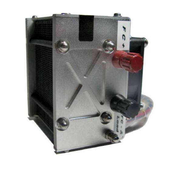
2. Terminology PEM fuel cell: A PEM (Proton Exchange Membrane) fuel cell is a device that converts hydrogen and oxygen into water and electricity. A fuel cell stack: It includes a plurality of plate-like fuel cells arranged along an axis generally parallel to cell thickness with electrically conductive separator plates between each pair of cells. - Page 10 A: Warning labels B: FC+ connector C: FC- & load- connector D: Grounding cable connector E: Controller multi-connector F: H2 supply valve G: H2 purge valve H: Fuel cell air inlet side Note: Pictures in the manual are only for reference, takes material object as the standard.
- Page 11 A: H2 inlet connector B: Blower C: H2 outlet connector D: Silicon tube Note: The silicon tube connected between the hydrogen input and hydrogen output is to keep the membrane humidity to maintain the fuel cell stack in best performance. After the stack is finished using, connect the silicon tube between the input and output for keeping the membrane humidity.
- Page 12 A: Horizon Logo B: LED C: Product No.Label D: Connect plug E: SCU(short circuit units) switch F: ON/OFF button G: Connect to FC+ H: Connect to FC- I: Connect to Load+ J: Controller power supply DC 13V+ K: Controller power supply DC 13V- L: LCD connector (optional LCD, not provided) Manual_FCS-C100_V2.2_EN...
-
Page 13: Stack And System Component Information
3. Stack and System Component Information 1. Stack Is made up of plate-like cells with air channels to allow the flow of air across the membrane. The membrane facilitates the flow of Hydrogen creating the release of electrons. Electrically conductive separator plates between each pair of cells enable the flow of electrons. - Page 14 7. Controller Connector Connect the stack to the T-sensor/blower/purging valve/ input valve on the controller. 8. Controller Controls the stack temperature, blowers, hydrogen input, purging and short circuiting of the stack. 9. H2 Input/Output connectors H2 OUT: connect the tube shown in 11 below. H2 IN: connect the tube shown in 11 below.
-
Page 15: Technical Specification
4. Technical Specification Type of fuel cell Number of cells Rated Power 100W Performance 12V @8.3A H2 Supply valve voltage Purging valve voltage Blower voltage Reactant ydrogen and Air External temperature 5 to 30ºC Max. stack temperature 65ºC H2 Pressur .45-0.55bar Hydrogen purity ≧... -
Page 16: System Set-Up
5. System Set-Up PLEASE READ CAREFULLY BEFORE STARTING WARNINGS: 1. The tube between the hydrogen pressure regulator and the fuel cell gas input is required to be less than 30cm. The inner diameter of the hydrogen supply tube is required to be more than 3mm. The input pressure to the stack is required to be 0.45-0.55Bar . - Page 17 STEP 2: Connect the controller to the stack as the output power also shall be under control. Use the grounding cable to connect the FC-&Load - to the grounding connector. The finished connection is shown in 2D. Note: After the fuel cell stack is finished using, disconnect the grounding cable. Manual_FCS-C100_V2.2_EN...
- Page 18 STEP 3: Keep the SCU (Short Circuit Unit) switch ON at “-” for usual use. Warning: Some home appliances may not be suitable for this activation process. It may cause damaging. you can shut off the short circuit by switching it to "O", but it will cause at least 20% performance loss.
- Page 19 Warning:The tube between the hydrogen pressure regulator and the fuel cell gas input is required to be less than 30cm. STEP 5: Connect the stack to the purge valve through the filter for a longer runtime and a better performance (5A-5E). If not, the gas out of stack may have a negative effect on the purge valve after a long-time running.
- Page 20 metal nozzle: input plastic nozzle : output Note: The tube is required to be less than 20cm between stack output and purging valve. The tube connected to the purging valve output is required to be less than 30cm. The inner diameter of the required to be more than 2mm.
- Page 21 STEP 6: Check all the connection first and connect the load to the system, Load+ is linked to the "load+" at the controller, Load- links to the "FC- and load-" in the stack shown in 6A STEP 7: Direct the outlet tubing of the purge valve away from the fuel cell. Do not let the purged hydrogen go back towards the fuel cell stack, this will damage the fuel cell.
- Page 22 STEP 8: Connect the controller to a stabilized power supply through the “13V DC” connectors (8A). The external power supply is required to be 13V(±1V), <5A. STEP 9: Connect the Hydrogen supply to the hydrogen supply valve, and make sure the hydrogen pressure is between 0.45-0.55Bar.
-
Page 23: System Setup Diagram
6. System Setup Diagram FC- & Load- SCU: Short Circuit Unit GND: Grounding Manual_FCS-C100_V2.2_EN... -
Page 24: Notes For The Set Up
7. Notes for the set-up Stack should be placed like this The voltage of external power supply is position. Stand on the plastic feet. between 12V-14V, the current range is different based on the different stack. The tube is required to be less than 20cm between stack output and purging valve. -
Page 25: Operating Procedures
8. Operating Procedures STARTUP PROCEDURE Make sure both the stack and the ambient temperature are less than 45℃. Otherwise the system will not start up successfully . Hold the ON/OFF button down for 2 seconds to start the system; you will hear one beep, which means the system has started. - Page 26 RUNNING PROCEDURE After system has started, depending on your setup and application you can change your load to get the power you need within the specified power range for this fuel cell. Don’t connect up a load that will demand power more than 100W which can permanently damage the fuel cell.
- Page 27 SHUTDOWN PROCEDURE To shut down the fuel cell system down, please follow these steps: 1. Turn off the load. 2. Hold the ON/OFF button down for 2 seconds to stop the system, you will hear one long beep, which means the system is shutting down. Note: When you turn off the on/off switch connected to the control box at the temperature of the fuel cell stack higher than 45˚C the stack will not stop working...
-
Page 28: Performance Characteristics
9. Performance Characteristics Performance characteristics of the stack are presented. All performance data is given for baseline operating conditions, defined at sea-level and room ambient temperature. 100W U-I Curve Current(A) H2 consump n(ml/min) 1200 1000 20.0 40.0 60.0 80.0 100.0 120.0 Power(w) 100W Power Curve... -
Page 29: Storage And Re-Use
10. Storage and Re-Use When finished operating the stack, place it in an enclosed area for storage to keep the stack from getting too dry. The stack should be stored at room temperature. If the stack is un-used for a long period of time (more than 4 weeks) and it's performance goes down 50% to the rated power at 12V after 30 minutes operation, we recommend do the following steps. -
Page 30: Trouble Shooting&System Checks
11. Trouble Shooting & system checks Check the external power supply The battery might not be operating correctly or in the case of a battery may not have any charge left. Disconnect the external power source. Using a multimeter take a reading of the positive and negative connection points on the external power connectors to the controller. - Page 31 Bleeps Interpretation Action High current protection i.e. current is too high - For H-100 - H-300 is > 12A set by the controller. - For H-500 - H-1000 is > 30A set by the controller. High temperature fuel cell protection i.e. fuel cell is running >65˚C.
- Page 32 Checking the Fuel Cell System If the fuel cell shuts down you need to check the voltage of the fuel cell by measuring between the FC+ and FC- connectors on the fuel cell. There are 3 possible scenarios: Voltage = 0 Check the supply valve and purge are open.
- Page 33 Check the Blowers With the system completely setup, Start the system. Once the system has started, after the fuel cell system has been short circuited 5 times as part of the startup procedure the blowers will start to turn, pulling air through the fuel cell. If all the blower(s) are creating non-standard noise, turning slowly, or not turning at all.
-
Page 34: Fuel Cell Drawing
12. FUEL CELL DRAWING Manual_FCS-C100_V2.2_EN... -
Page 35: Faq
13. FAQ What is the SCU? This is the Short Circuit Unit, it helps to condition the fuel cell for long term good performance. What is the Hydrogen pressure supplied to the fuel cell stack? The pressure is required to be 0.45-0.55Bar. What is the maintenance of the stacks? 1.
Need help?
Do you have a question about the H-100 and is the answer not in the manual?
Questions and answers