Table of Contents
Advertisement
Quick Links
www.ti.com
User's Guide
DRV8311HEVM User's Guide
This document is provided with the
3-V to 20-V Three-Phase Smart Gate
shows how to set up and power the board with the
LaunchPad™ development
The DRV8311HEVM comes automatically populated with and configured for the DRV8311H hardware
device. It is also compatible for the DRV8311S and DRV8311P variants, but the user will need to
modify the board to make it compatible for the SPI/tSPI devices (see
For the DRV8311H Hardware settings to work, R7 must be removed and 3.3 V must be supplied
externally or from the LaunchPad. Please see section DRV8311H Compatability.
Warnings..........................................................................................................................................................2
2
Introduction.............................................................................................................................................................................3
Guide....................................................................................................................................................................5
4.2 Connection Details.............................................................................................................................................................
Lights..........................................................................................................................................................................8
4.4 DRV8311HEVM Configurability - Jumpers and Resistors.................................................................................................
5 Hardware Setup....................................................................................................................................................................
Application.............................................................................................................................................16
6.1 C2000 InstaSPIN Universal GUI......................................................................................................................................
Identification...........................................................................................................................................................17
6.3 Sensorless-FOC Commutation........................................................................................................................................
7
Schematics............................................................................................................................................................................21
7.1 Main Supply / Status LEDs..............................................................................................................................................
7.2
DRV8311H/S/P.................................................................................................................................................................21
7.3 3.3V Buck Regulator........................................................................................................................................................
Reference............................................................................................................................................................23
7.5 LaunchPad Connections..................................................................................................................................................
7.6 Connectors & Interface....................................................................................................................................................
7.7 Voltage Sense & Protection.............................................................................................................................................
8 Revision History...................................................................................................................................................................
Trademarks
All trademarks are the property of their respective owners.
SLOU552 - JULY 2021
Submit Document Feedback
DRV8311HEVM customer evaluation module
Driver. This User's Guide details the implementation of the EVM and
kit).
Table of Contents
Overview.........................................................................................................................................6
only).............................................................................................................................19
Copyright © 2021 Texas Instruments Incorporated
ABSTRACT
LAUNCHXL-F280049C (C2000 Piccolo MCU F280049C
Note
Section
Note
LAUNCHXL-F280049C................................................................6
Techniques..........................................................................19
Table of Contents
(EVM)to evaluate the
DRV8311
4.4).
DRV8311HEVM User's Guide
6
9
15
16
18
21
22
23
24
25
26
1
Advertisement
Table of Contents

Related Manuals for Texas Instruments DRV8311HEVM


Summary of Contents for Texas Instruments DRV8311HEVM
-
Page 1: Table Of Contents
Note The DRV8311HEVM comes automatically populated with and configured for the DRV8311H hardware device. It is also compatible for the DRV8311S and DRV8311P variants, but the user will need to modify the board to make it compatible for the SPI/tSPI devices (see Section 4.4). -
Page 2: Cautions And Warnings
Observe the following cautions and warnings as printed on the EVM board. HOT SURFACE: Caution Hot Surface! Contact may cause burns. Do not touch. Please take the proper precautions when operating. DRV8311HEVM User's Guide SLOU552 – JULY 2021 Submit Document Feedback Copyright © 2021 Texas Instruments Incorporated... -
Page 3: Introduction
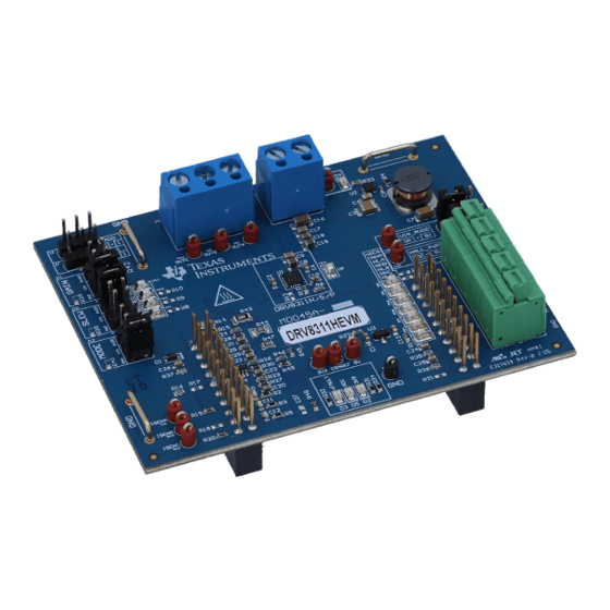
It also is intended to help engineers design, implement, and validate reference hardware and software for the LaunchPad MCU and DRV8311. For step by step details on connecting the LAUNCHXL- F280049C + DRV8311HEVM, installing software, and running the project to spin a motor, refer to Section SLOU552 –... - Page 4 Introduction www.ti.com Figure 2-1. DRV8311HEVM PCB Layout DRV8311HEVM User's Guide SLOU552 – JULY 2021 Submit Document Feedback Copyright © 2021 Texas Instruments Incorporated...
-
Page 5: Quick Start Guide
Quick Start Guide 3 Quick Start Guide The DRV8311HEVM requires a power supply with a recommended operating range from 3-V to 20-V. To setup and power the EVM, follow the sequence below: 1. Connect the power supply ground to the GND of the 2-pin power connector J3 and the power supply positive terminal to the VM pin of J3. -
Page 6: Hardware And Software Overview
4.2 Connection Details Figure 4-2 shows the power supply and motor connections made to the DRV8311HEVM in order to spin a 3-phase sensored or sensorless Brushless-DC motor. A 3-V to 20-V power supply or battery is connected to the VM and GND terminals. The three phases of the BLDC motor connect directly to the OUTA, OUTB, and OUTC terminals of the screw terminal provided on the DRV8311HEVM. - Page 7 Micro-USB cable is plugged in to the LAUNCHXL-F280049C to provide communication between the LaunchPad firmware and GUI as well as the correct installment of the DRV8311HEVM to the J1/J3 and J2/J4 headers of the LaunchPad. SLOU552 – JULY 2021...
-
Page 8: Led Lights
USB cable is plugged in to the LaunchPad. The DRV8311HEVM has 4 status LEDs on the board. By default, the VM and 3V3 LEDs will light up when the board is powered on. The fault LED will light up when the driver reports a fault, and the MCU LED (tied to GPIO59) can be used for debugging and validation. -
Page 9: Drv8311Hevm Configurability - Jumpers And Resistors
Figure 4-4. DRV8311HEVM LEDs 4.4 DRV8311HEVM Configurability – Jumpers and Resistors The DRV8311HEVM includes a variety of user-selectable jumpers and unpopulated components on the PCB to choose user settings and evaluate the DRV8311S, DRV8311H, or DRV8311P device. A summary of those... - Page 10 Hardware and Software Overview www.ti.com Table 4-2. Description of user selectable settings on DRV8311HEVM (H variant defaults in bold) (continued) Setting Name Description Position Function GAIN select (DRV8311H only) Use J11 J11 = Bottom 0.25 V/A to select desired gain J11 = Middle 0.5 V/A...
- Page 11 Figure 4-5. User-selectable jumpers and DNP components on DRV8311HEVM 4.4.1 DRV8311H Compatibility The DRV8311HEVM default is the DRV8311H (Hardware variant), which can be used to spin a 3-phase Brushless-DC motor with selectable modes configured with hardware settings as shown in Table 4-3.
- Page 12 The DRV8311HEVM is compatible with the DRV8311P (tSPI variant) to spin a 3-phase Brushless-DC motor using enhanced Texas Instruments SPI (tSPI). tSPI is a protocol that allows for multiple motor drivers to be controlled via one SPI bus. Each device has a selectable address in hardware and tSPI protocol allows for individual control of each driver through SPI communication from a single microcontroller unit (MCU).
- Page 13 Hardware and Software Overview 4.4.5 Interfacing DRV8311HEVM and LAUNCHXL-F280049C LaunchPad The DRV8311HEVM has 40 pins with different functions. These pins are interfaced with the LAUNCHXLF280049C LaunchPad development kit and are mapped appropriately to receive the functionalities of the DRV8311H device. These 40 pins are grouped into 4 ports in respect to the LAUNCHXL-F280049C (J1 to J4).
- Page 14 Hardware and Software Overview www.ti.com Table 4-6. Connections for Header J2 on DRV8311HEVM (continued) J2 Pin Number DRV8311HEVM Function LAUNCHXL-F280049C Function Description INLB/PWM_SYNC GPIO9/PWM5B PWM used to switch Low-side FET of Phase B (DRV8311H and DRV8311S), or PWM used to...
-
Page 15: Hardware Setup
The hardware required to run the motor control is the LAUNCHXL-F280049C LaunchPad development kit, the DRV8311HEVM, a Micro-USB cable, and a power supply with a DC output from 3-V to 20-V. Follow these steps to set up the evaluation module: 1) Ensure all resistors or jumpers are set up accordingly according to the device variant used. -
Page 16: Firmware And Gui Application
Library of motor solutions. The firmware includes motor identification and a sensorless FOC algorithm to spin the motor. The firmware uses the DRV8311HEVM InstaSPIN Universal GUI to run the algorithm and includes tabs to read from and write to the DRV8311 SPI registers (DRV8311S only). -
Page 17: Motor Identification
Rs, Rs Online, Ls-d, Ls-q, Flux, and Rr will update for that motor as shown in Figure 6-4. These values will be automatically used for Field-oriented control. SLOU552 – JULY 2021 DRV8311HEVM User's Guide Submit Document Feedback Copyright © 2021 Texas Instruments Incorporated... -
Page 18: Sensorless-Foc Commutation
Figure 6-3. C2000 InstaSPIN Universal GUI Running motor identification Figure 6-4. Motor identification complete using the DRV8311HEVM InstaSPIN GUI 6.3 Sensorless-FOC Commutation 1. To spin the motor with sensorless FOC, check the “Run” box again. The motor will spin with sinusoidal current at the speedRef (Hz) value in the GUI, which is automatically set to 20.0 Hz. -
Page 19: Torque Control, Speed Control, And Advanced Modulation Techniques
6.4 Torque Control, Speed Control, and Advanced Modulation Techniques To implement more advanced modulation techniques such as torque control, speed control, and algorithms such as MTPA, Field-weakening, and PowerWarp (EPL) using the DRV8311HEVM InstaSPIN Universal GUI, please consult the MotorControl SDK InstaSPIN Lab Guide found in MotorControl SDK. - Page 20 Firmware and GUI Application www.ti.com Figure 6-6. DRV8311HEVM InstaSPIN GUI SPI Control Registers DRV8311HEVM User's Guide SLOU552 – JULY 2021 Submit Document Feedback Copyright © 2021 Texas Instruments Incorporated...
-
Page 21: Schematics
Schematics 7 Schematics 7.1 Main Supply / Status LEDs Figure 7-1. Main Supply / Status LEDs schematic 7.2 DRV8311H/S/P Figure 7-2. DRV8311H/S/P schematic SLOU552 – JULY 2021 DRV8311HEVM User's Guide Submit Document Feedback Copyright © 2021 Texas Instruments Incorporated... -
Page 22: Buck Regulator
Schematics www.ti.com 7.3 3.3V Buck Regulator Figure 7-3. 3.3V Buck Regulator schematic DRV8311HEVM User's Guide SLOU552 – JULY 2021 Submit Document Feedback Copyright © 2021 Texas Instruments Incorporated... -
Page 23: Voltage Reference
Schematics 7.4 Voltage Reference Figure 7-4. Voltage Reference schematic 7.5 LaunchPad Connections Figure 7-5. LaunchPad Connections schematic SLOU552 – JULY 2021 DRV8311HEVM User's Guide Submit Document Feedback Copyright © 2021 Texas Instruments Incorporated... -
Page 24: Connectors & Interface
Schematics www.ti.com 7.6 Connectors & Interface Figure 7-6. Connectors & Interface schematic DRV8311HEVM User's Guide SLOU552 – JULY 2021 Submit Document Feedback Copyright © 2021 Texas Instruments Incorporated... -
Page 25: Voltage Sense & Protection
Schematics 7.7 Voltage Sense & Protection Figure 7-7. Voltage Sense & Protection schematic SLOU552 – JULY 2021 DRV8311HEVM User's Guide Submit Document Feedback Copyright © 2021 Texas Instruments Incorporated... -
Page 26: Revision History
8 Revision History NOTE: Page numbers for previous revisions may differ from page numbers in the current version. DATE REVISION NOTES August 2021 Initial Release DRV8311HEVM User's Guide SLOU552 – JULY 2021 Submit Document Feedback Copyright © 2021 Texas Instruments Incorporated... - Page 27 TI products. TI’s provision of these resources does not expand or otherwise alter TI’s applicable warranties or warranty disclaimers for TI products.IMPORTANT NOTICE Mailing Address: Texas Instruments, Post Office Box 655303, Dallas, Texas 75265 Copyright © 2021, Texas Instruments Incorporated...
Need help?
Do you have a question about the DRV8311HEVM and is the answer not in the manual?
Questions and answers