Table of Contents
Advertisement
Quick Links
Manual F-20-TFP-G
June 2008
Revision 1
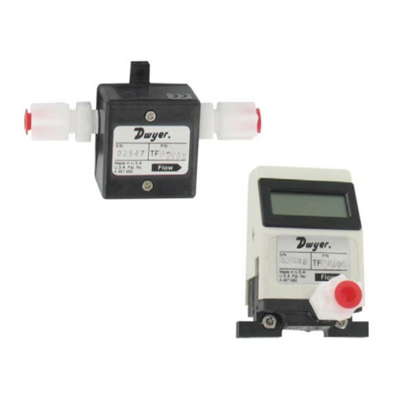
MODEL TFP-GI
MODEL TFP-GV
Flow Sensors and Flow Meters For Gases
Installation Manual & Operating Instructions
READ THIS MANUAL COMPLETELY BEFORE ATTEMPTING TO CONNECT
OR OPERATE YOUR FLOW SENSOR. FAILURE TO DO SO MAY RESULT
IN INJURY TO YOU OR DAMAGE TO THE FLOW SENSOR.
1.800.561.8187
information@itm.com
www.
.com
Advertisement
Table of Contents

Related Manuals for Dwyer Instruments TFP-GI Series


Summary of Contents for Dwyer Instruments TFP-GI Series
- Page 1 Manual F-20-TFP-G June 2008 Revision 1 MODEL TFP-GI MODEL TFP-GV Flow Sensors and Flow Meters For Gases Installation Manual & Operating Instructions READ THIS MANUAL COMPLETELY BEFORE ATTEMPTING TO CONNECT OR OPERATE YOUR FLOW SENSOR. FAILURE TO DO SO MAY RESULT IN INJURY TO YOU OR DAMAGE TO THE FLOW SENSOR.
-
Page 2: Table Of Contents
T A B L E C O N T E N T S A. Introduction ................3 1. Unpacking ..................3 2. Product Overview And Principle Of Operation ........ 4 Installation................5 1. General Considerations ..............5 2. Mounting The Flow Sensor Or Flow Meter ........5 3. -
Page 3: Introduction
Dwyer Instruments is not liable for damage to the device once it has left the manufacturing premises. Open the package from the top, taking care not to cut too deeply into the package. -
Page 4: Product Overview And Principle Of Operation
Product Overview and Principle of Operation TFP Series Flow Meters and Flow Sensors for gases are capable of measuring volumetric flows as low as 20-100 ml/min or as high as 100- 500 l/min. Highly repeatable results are achieved using a patented Pelton Turbine Wheel flow sensor design. -
Page 5: Installation
Installation CAUTION: Do not exceed the pressure, temperature or power operating ranges detailed in the Specifications section of this manual. Dwyer Instruments shall not be liable for any damage or injury caused by incorrect operation of their products. General Considerations It is recommended that a safety shut-off valve be installed upstream of (before) the sensor. -
Page 6: Tubing Connections
Only use the factory installed fittings on the unit. If the fittings are removed the calibration of the unit may be effected and leaking may occur. If different fittings are required please contact the Dwyer Instruments Service Department for assistance. - Page 7 Connecting and tightening the Fittings CAUTION: DO NOT over tighten the fittings into the sensor body. Excessive force may damage the sensor body. This type of damage will NOT be repaired under warranty. The flow direction for the unit is clearly marked on the label. Do not reverse the flow direction or the unit will not function.
-
Page 8: Electrical Connections
This output may be connected to a display, data acquisition system or voltmeter. The TFP-GI Series features an integral display that provides a local flow reading. These units also have a 0-5VDC analog output available. If required, this may be connected to another display, data acquisition system or voltmeter. -
Page 9: C) Electrical Connections - Voltage Output Units
Electrical Connections – Voltage Output Units The cable assembly should be connected to the sensor as detailed in section 4(b) above. Do not apply power to the sensor until all the connections have been made and checked. Electrical connections should be made as follows: Wiring Schematic For Voltage Output Units. -
Page 10: D) Using A 0-5Vdc Output Power Adapter Package
d) Using a 0-5VDC Output Power Adapter Package. An optional 0-5VDC Output Power Adapter Package is available for use with the TFP Series. The 0-5VDC Output Power Adapter Package consists of a power source (115VAC or 230VAC) and cable assembly with pig-tail (soldered wire) ends for the signal output. -
Page 11: Operation
The TFP-GV Series for gases provides a 0-5VDC output proportional to the volumetric flow rate. The TFP-GI Series features an integral 3.5 digit display that provides a local flow reading and a 0-5VDC analog output proportional to the volumetric flow rate. -
Page 12: B) Units With An Integral Display
Units With An Integral Display The TFP-GI Series features an integral 3.5 digit LCD display. This is configured to read in ml/min for flow ranges up to 100-500 ml/min and in l/min for all other flow ranges. The display will only operate if power is applied to the unit. -
Page 13: B) Flows Below The Minimum Rated Flow
b) Flows Below The Minimum Rated Flow. Signal outputs may be obtained at flow rates below the minimum specified for your unit. The amount of flow that may be measured below the minimum specified varies from unit to unit. Zero Adjustments It is impossible for there to be any zero drift so zero adjustments are never required. - Page 14 For example, if the unit is calibrated for AIR but the user wants to measure the flow of Carbon Dioxide (CO ) with a specific gravity of 1.517 the flow reading correction factor would be calculated as follows: = Specific gravity of CO = 1.517 = Specific gravity of Air = 1.000 current...
-
Page 15: Maintenance And Product Care
It should be noted that the maximum output voltage for the units is approximately 5.9VDC. It is not possible to adjust units if an output of greater than 5.9 VDC is required. Adjusting the Gain Potentiometer Using a Flat Head Screwdriver (TFP-GV Series shown, other models similar) Maintenance And Product Care General... -
Page 16: Cleaning And Flushing
Cleaning and Flushing If there is a buildup of deposits or particles from the measured gases it may or flush be necessary to clean the unit. This should be done by flowing clean, particle free air (or Nitrogen) through the unit at a flow rate, pressure and temperature within the specifications of the unit. -
Page 17: Specifications
Specifications Model TFP-GV Model TFP-GI Display None 3.5 Digit LCD, 0.39” (10mm) high digits Accuracy (including linearity) ±3.0% Full Scale* Repeatability ±0.5% Full Scale* Pressure Rating 40 psig (2.8 bar) Temperature Rating Operating Range: 5 to 55°C Storage Range: 0 to 70°C Temperature Sensitivity ±0.2% F.S.* or less per °C Wetted Materials... -
Page 18: Connector Pin And Wire Color Cross Reference
Connector Pin And Wire Color Cross Reference Pin Configuration For Connector Socket And Connector Cable Wire Color Description Black Signal & Power Negative (Ground) White Voltage Output Power Positive Green Not Used F-20-TFP-G, pg. 18 of 27 1.800.561.8187 information@itm.com www. .com... -
Page 19: Dimensions
Dimensions ALL DIMENSIONS IN INCHES (MILLIMETERS IN BRACKETS) TFP-GV Series For Gases 20-200 ml/min To 1.0-5.0 l/min Units 1/4” Acetal Fittings Shown F-20-TFP-G, pg. 19 of 27 1.800.561.8187 information@itm.com www. .com... - Page 20 TFP-GV Series For Gases 2.0-10.0 l/min Units 1/4” Acetal Fittings Shown F-20-TFP-G, pg. 20 of 27 1.800.561.8187 information@itm.com www. .com...
- Page 21 TFP-GV Series For Gases 4.0-20.0 l/min To 100-500 l/min Units 1/2” Acetal Fittings Shown F-20-TFP-G, pg. 21 of 27 1.800.561.8187 information@itm.com www. .com...
- Page 22 TFP-GI Series For Gases 20-200 ml/min To 1.0-5.0 l/min Units 1/4” Acetal Fittings Shown F-20-TFP-G, pg. 22 of 27 1.800.561.8187 information@itm.com www. .com...
- Page 23 TFP-GI Series For Gases 2.0-10.0 l/min Units 1/4” Acetal Fittings Shown F-20-TFP-G, pg. 23 of 27 1.800.561.8187 information@itm.com www. .com...
- Page 24 TFP-GI Series For Gases 4.0-20.0 l/min To 100-500 l/min Units 1/2” Acetal Fittings Shown F-20-TFP-G, pg. 24 of 27 1.800.561.8187 information@itm.com www. .com...
-
Page 25: Troubleshooting Guide
Troubleshooting Guide Symptom Possible Cause Method of Correction Unit Leaks. Fittings not tight enough. Tighten fittings (see section B3). Sensor assembly cracked. Unit must be returned for repair (see Section D3). No output signal or No power or low power. Apply correct power. - Page 26 Symptom Possible Cause Method of Correction Flow indication is not Attempting to measure flows Use higher flow rates. linear and output too below the specified low at lower flows. minimum for the unit. Moisture or liquid in sensor. Remove moisture and allow sensor to dry out.
-
Page 27: Limited Warranty
Limited Warranty After final installation of the flow meter, no routine maintenance is required. A periodic check of system calibration is suggested. The series TFP-GV and TFP-GI are not field repairable and should be returned if repair is needed (field repair should not be attempted and may void the warranty).
Need help?
Do you have a question about the TFP-GI Series and is the answer not in the manual?
Questions and answers