Advertisement
Quick Links
®
PAS
Micro Series
Self-contained respiratory protection equipment
1
Safety-related information
●
Before using this product, carefully read the instructions for use.
●
Strictly follow the instructions for use. The user must fully understand
and strictly observe the instructions. Use the product only for the
purposes specified in the intended use section of this document.
●
Do not dispose of the instructions for use. Ensure that they are
retained and appropriately used by the product user.
●
Only fully trained and competent users are permitted to use this product.
●
Comply with all local and national rules and regulations associated
with this product.
●
Only trained and competent personnel are permitted to inspect, repair and
service the product. Dräger recommend a Dräger service contract for all
maintenance activities and that all repairs are carried out by Dräger.
●
Properly trained service personnel must inspect and service this
product as detailed in the Maintenance section of this document.
●
Use only genuine Dräger spare parts and accessories, or the proper
functioning of the product may be impaired.
●
Do not use a faulty or incomplete product, and do not modify the product.
●
Notify Dräger in the event of any component fault or failure.
●
All approved respiratory equipment shall be selected, fitted, used, and
maintained in accordance with OSHA, and other applicable regulations.
●
The air supply shall meet the requirements for breathing air according
to CGA G-7.1 Grade D or higher quality.
2
Conventions used in this document
2.1
Definitions of alert icons
Alert icons are used in this document to provide and highlight text that
requires a greater awareness by the user. A definition of the meaning of
each icon is as follows:
WARNING
Indicates a potentially hazardous situation which, if not avoided, could
result in death or serious injury.
CAUTION
Indicates a potentially hazardous situation which, if not avoided, could
result in physical injury. It may also be used to alert against unsafe
practices.
NOTICE
Indicates a situation which, if not avoided, could result in damage to the
product or environment.
2.2
Registered trademarks
Trademark
Trademark owner
Dow Corning Corporation in the United States and/or
Dow Corning
®
and
other countries
Molykote
®
®
Dräger
PAS
The trademarks listed are only registered in certain countries and not
necessarily in the country in which this material is sold.
2.3
Abbreviations
Abbreviation Explanation
CBRN
Chemical, biological, radiological and nuclear
CGA
Compressed Gas Association
EOSTI
End of service time indicator
IDLH
Immediately dangerous to life or health
LDV
Lung demand valve
NIOSH
National Institute for Occupational Safety and Health
NFPA
National Fire Protection Association
OSHA
Occupational Safety and Health Administration
3
Description
3.1
Product overview
®
This variant of the Dräger PAS
Micro series uses breathing air from a
compressed air cylinder to provide respiratory protection for working in a
contaminated (IDLH) environment.
The equipment is classified by NIOSH with a prescribed service time of
15 minutes. The actual service time could vary from this value depending
on the cylinder pressure at the start of the operation and the rate at which
the wearer uses air (the respiratory rate).
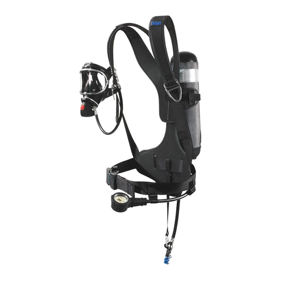
●
The first-stage regulator (Fig A, Item 4) connects to the cylinder, and
reduces the cylinder pressure to the medium pressure required at the
lung demand valve (Fig A, Item 1).
●
The whistle on the first-stage regulator is an end of service time
indicator (EOSTI). The whistle commences to provide an alarm when
the remaining service time of the equipment is reduced to 25 % of the
rated service time.
●
The pressure gauge (Fig A, Item 3) displays the cylinder pressure
during use.
●
The carrying system has a shoulder harness, a waist belt, and a
cylinder strap on the rear.
3.1.1
Compressed air cylinder
The compressed air cylinder is a specific composite cylinder with a working
pressure rating of 4500 psi. The cylinder valve has an integral pressure
gauge. See the cylinder instructions for use for further information.
3.1.2
Lung demand valve
The features and components of the Dräger lung demand valves approved
®
for use with PAS
Micro are:
●
The lung demand valve switches on automatically as the wearer
breathes (first-breath activation), and then regulates the air supply into
the mask in response to the respiratory rate of the wearer.
●
The reset button (Fig B, Item 1) is used to switch off the air flow
through the lung demand valve.
●
The front button (Fig B, Item 2) is used to switch on the lung demand
valve manually.
3352430
© Dräger Safety UK Limited
Edition 09 – November 2018 (Edition 01 – October 2005)
Subject to alteration
A
2
1
3
B
4
OFF
ON
3
C
D
1
5121
E
1
2
F
G
3625
●
The bypass button (Fig B, Item 3) is used to activate an internal valve
which supplies additional air into the mask.
○
Pressing, turning, and then releasing the bypass button turns the
additional air supply on/off. The additional air supply is: off when
the red dots are aligned; on when the red dots are misaligned.
○
Pressing and releasing the bypass button with the red dots aligned
supplies a short jet of additional air.
●
The outlet (Fig B, Item 4) is a male push-in connector with a sealing O-
ring.
●
The lung demand valve is either integral or removable. On integral
variants, the medium-pressure hose connects directly to the first-stage
regulator. Removable variants have a medium-pressure coupling
(Fig A, Item 2) which allows quick removal and fitting of the lung
demand valve when required.
●
A Dräger NFPA flushing-type lung demand valve is approved for use
with this product. When used, it provides extra protection in
contaminated environments.
See the lung demand valve instructions for use for further information.
3.1.3
Face mask
A number of Dräger face masks are approved for use with PAS
See the face mask instructions for use for information about the mask.
3.2
Intended use
When used with an approved face mask, compressed air cylinder, and
lung demand valve, the product provides the wearer with respiratory
protection for working in contaminated or oxygen-deficient conditions.
The face mask, air cylinder, lung demand valve, and other accessories
used with this product must be listed in the Dräger approval matrix. The
product must be assembled in an approved configuration, or operation of
the device could be impaired. Contact Dräger for further information.
3.3
Limitations on use
●
This product is not approved for use in firefighting or CBRN applications.
®
●
When the PAS
Micro is used with the Dräger FPS 7000 face mask,
only the Dräger NFPA flushing-type lung demand valve can be used.
3.4
Approvals
The Dräger PAS
®
Micro self-contained respiratory protection equipment
conforms to the requirements of NIOSH. The equipment must only be used
with compressed air cylinders that are approved by NIOSH.
4
Use
WARNING
The service time of the equipment depends on the initial air supply
available and the respiratory rate of the wearer.
► Charge the air cylinder to its full rated pressure before use.
► Do not commence any operation using a cylinder that is less than 90 % full.
Instructions for Use
i
CAUTION
Equipment damage could cause the release of high-pressure air.
► Do not apply excessive force or use tools to open or close the cylinder
valve.
► Do not drop or throw down the equipment.
4
4.1
Preparation for use
4.1.1
Visual inspection
1599/1602
Carry out a visual inspection, checking the full respiratory protection
1
equipment, including all component parts and accessories. Check that the
equipment is clean and undamaged, paying particular attention to
pneumatic components, hoses and connectors. Typical signs of damage
that may affect the operation of the equipment include impact, abrasion,
cutting, corrosion and discoloration. Report damage to service personnel
or Dräger, and do not use the equipment until faults are rectified.
2
4.1.2
Fitting the cylinder
1. Ensure that the cylinder is fully charged.
2. Place the equipment on a clean flat surface.
3953
3. Fully extend the cylinder strap.
4. Check the threads of the cylinder valve and first-stage regulator.
5. Ensure that the O-ring (Fig C, Item 1) is clean and undamaged.
6. Insert the cylinder through the cylinder strap (Fig D), ensuring that it
remains clear of the hand wheel of the first-stage regulator to prevent
damage. Align the cylinder valve with the first-stage regulator.
7. Connect first-stage regulator to the cylinder valve. Do not fully tighten.
8. Secure the cylinder strap (Fig E):
a. Take up the slack to tighten the cylinder strap (1).
b. Pull the strap through the buckle to secure (2).
c. Insert the strap end into the securing band (3).
4. Fully hand tighten the hand wheel. Do not use tools or over tighten.
1624
4.1.3
Functional testing – High-pressure leak test and whistle test
3
WARNING
If the equipment fails to meet any of the standards or parameters in the
functional tests, or if an immediate leak is evident, there is a system fault.
► Investigate and repair any fault before use, or report the fault to
service personnel or Dräger. Do not use the equipment until the fault
condition is rectified.
3736
1. For equipment with a medium-pressure coupling (Fig A, Item 2),
disconnect and then reconnect the male coupling. To connect, press
3
the male coupling into the female coupling until an audible click is
2
heard. If there is any difficulty disconnecting or connecting, see the
troubleshooting information (Section 5).
2. Press the reset button (Fig B, Item 1).
3. Open the cylinder valve slowly, but fully, to pressurize the system.
During pressurization the whistle will sound briefly.
1
○
After storage at temperatures below 32 °F (0 °C), leakage could
be observed when the cylinder valve is initially opened due to ice
formation.
–
If leakage is observed from the lung demand valve, press the
3626
front button (Fig B, Item 2) to allow a rush of air to pass
through the lung demand valve and then quickly press the
reset button (Fig B, Item 1). Resume normal operation.
–
If leakage still occurs, remove the equipment from service and
report the fault to service personnel or Dräger.
4. Fully close the cylinder valve.
5. After 1 minute, reopen the cylinder valve while observing the pressure
gauge.
○
The gauge must not show an increase of more than 200 psi.
6. Fully close the cylinder valve.
7. Cover the lung demand valve outlet with the palm of the hand and
press the front button (Fig B, Item 2).
8. Carefully lift the palm of the hand to slowly vent the system until the
whistle activates, and observe the pressure displayed on the gauge.
○
The whistle must commence in the range 1215 to 1035 psi.
9. Press the reset button (Fig B, Item 1).
4.1.4
Putting on the PAS
See also Fig A which shows the PAS
1. Fully loosen the shoulder straps and waist belt and put on the
equipment.
2. Check that the shoulder pads are not twisted and take the weight on
the shoulders by pulling the shoulder straps. Do not fully tighten.
®
Micro.
3. Close the waist belt buckle and pull the ends of the waist belt until it fits
securely and comfortably.
4. Pull the shoulder straps until the equipment rests securely and
comfortably on the hips. Do not over tighten.
5. Align and push the lung demand valve into the mask until it latches in
position. Check the attachment by gently attempting to pull the
coupling apart.
6. Put the neck strap of the face mask over the head, and then insert the
neck strap stud into the hole in the center strap of the head harness.
4.1.5
Putting on the face mask
WARNING
Correct fit of the mask can only be achieved if the complete mask seal
makes contact with the skin.
► Head hair, facial hair, earrings, facial piercings, and normal spectacles
are not permitted in the sealing area. Hair styles that could affect the
mask fit (buns, pony-tails, hairpieces, etc.) are not permitted.
See also the face mask instructions for use.
1. Press the reset button (Fig B, Item 1).
2. Open the cylinder valve slowly, but fully, to pressurize the system.
3. Detach the neck strap stud from the center strap of the head harness.
4. Fully extend the straps and spread the head harness (Fig F).
5. Place the chin into the chin cup of the mask and pull the harness over
the head. Locate the harness center plate on back of the head.
6. See Fig G: tighten the lower (1) and then upper straps (2) evenly
towards the back of the head. Tighten the center strap (3) if necessary.
7. Breathe normally and carry out the mask function check.
Draeger Safety UK Limited
Ullswater Close
Blyth, NE24 4RG
United Kingdom
®
Micro (ready position)
®
Micro worn in the ready position.
Tel +44 1670 352 891
Fax +44 1670 356 266
www.draeger.com
3352430 (A3-D-P) Page 1 of 2
Advertisement

Subscribe to Our Youtube Channel
Related Manuals for Dräger PAS Micro Series


Summary of Contents for Dräger PAS Micro Series
- Page 1 ® Micro Series Instructions for Use Self-contained respiratory protection equipment Safety-related information CAUTION ● Before using this product, carefully read the instructions for use. Equipment damage could cause the release of high-pressure air. ● Strictly follow the instructions for use. The user must fully understand ►...
- Page 2 ® Micro Series Instructions for Use Self-contained respiratory protection equipment 4.1.6 Mask function check ● Recharge to the rated working pressure of the cylinder. Dräger Symptom Fault Remedy recommend a charge rate of 300 psi/minute (rapid charging will Difficulty connecting or Dirty connector Disconnect, clean, and 1.
Need help?
Do you have a question about the PAS Micro Series and is the answer not in the manual?
Questions and answers