Table of Contents
Advertisement
Quick Links
PAS
®
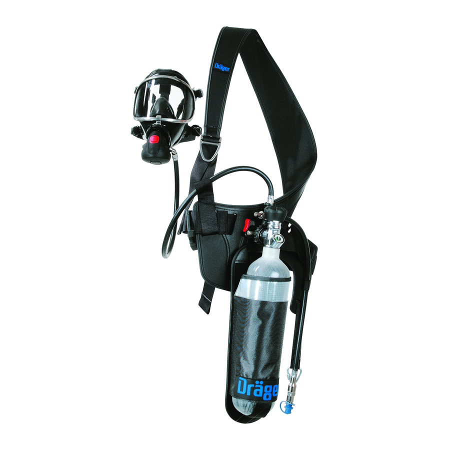
Colt Series
Bandolier short duration/Airline compressed air respiratory protection equipment
1
Approvals
The European standards, guidelines, and directives according to which
this product is approved are specified in the declaration of conformity (see
declaration of conformity or www.draeger.com/product-certificates).
2
For Your Safety
This variant of the Dräger PAS Colt Series of equipment incorporates a
preset and sealed pressure reducer. The associated lung demand valve
(LDV) has a preset and sealed balanced piston unit assembly. The Dräger
guarantee is void should original sealing caps of these units be tampered
with, removed, or broken. Correct operational condition is only valid if
Dräger service and re-seals the pressure reducer and balanced piston unit.
●
Use of this equipment requires wearer training and observance of
these Instructions for Use.
●
Use the equipment for the purpose specified in this instruction, or as
confirmed in writing by Dräger.
●
Use and maintenance of this equipment requires knowledge and
compliance with National Regulations, Laws and Standards governing
the use of respiratory equipment in the country of use.
●
Only trained competent personnel should inspect and service the
equipment at regular intervals and a record kept of such inspections
and service.
●
Only trained and competent personnel should carry out the charging of
the compressed air cylinders.
●
Dräger recommends a Service Contract be obtained from your Dräger
Branch or Agent.
●
Contact Dräger for details of Service Contracts and Service Training
Courses.
●
Use only original Dräger Spare Parts for service and maintenance.
●
Use only original Dräger Test Equipment for service and maintenance.
●
Notify Dräger if there is a component fault or failure.
3
Liability Statement
Terms and Conditions of warranty for the Dräger PAS Colt Series of
equipment can be obtained from Dräger on request. Responsibility for
reliable function of the equipment transfers to the owner or operator when
serviced or repaired by untrained personnel, (not employed or authorised
by Dräger), or when used in a manner not conforming to its intended use.
4
Description and Intended Use
The Dräger PAS Colt Series of Bandolier Short Duration/Airline equipment
consists of:
●
Bandolier Shoulder Harness with Waistbelt.
●
Hip Mounted Cylinder Carrying Holster.
●
Pressure Reducer with HP Gauge, Whistle Warning Unit (WWU) and
integral Lung Demand Valve (LDV).
Alternatively:
Pressure Reducer with HP Gauge, Whistle Warning Unit (WWU) and
medium pressure hose with Quick Release Coupling (QRC).
●
Airline Manifold Connection.
●
Valved Cylinder Assembly.
The equipment is available in either 10 minute or 15 minute nominal
duration versions.
4.1
Optional Variants
●
Cylinder Carrying Holster – Drop Down. If applicable, refer to
additional enclosed Instructions for Use.
4.2
Accessories
●
Thigh strap
This series of equipment is compatible with a range of lung demand valves,
face mask and compressed air cylinders. When used in approved carrying
system, valved cylinder assembly, LDV and face mask combinations, the
equipment provides the wearer with respiratory protection when working in
a contaminated or oxygen deficient gaseous atmosphere.
The effective duration of the equipment is dependant on the capacity
(volume) of the cylinder selected and the breathing rate of the wearer.
Details of the equipment variants, accessories, and any approved
independent air supply source configurations are available from Dräger on
request.
5
Technical Data
5.1
High Pressure Connections
Standard G5/8 as per EN 144-2.
200bar or 300bar
Other connections are available to national standards.
5.2
Whistle Setting
Preset by Dräger to 55bar +/-5bar
(60bar to 50bar)
5.3
LDV to Face mask Connection
Three variants of integral LDV's are available:
●
Push-In Type A - Positive Pressure (PP).
●
Screw-In Type AE - Positive Pressure (PP).
●
Screw-In Type N – Normal Demand (ND).
Refer to the Instructions for Use supplied with the face mask.
5.4
Compressed Air Cylinders
Cylinders are available in either steel, or composite materials. Contact
Dräger for details.
Cylinders supplied by Dräger are charged at an ambient temperature of
15 °C and to the nominal cylinder pressure.
5.5
Airline Manifold Connection
A Male Coupling is incorporated on the airline manifold for the connection
of a hose coupling from an independent air supply.
5.6
Airline Operating Pressures and Flow
The selected low pressure independent air supply must meet the following
parameters.
3352425
© Dräger Safety UK Limited
Edition 06 – October 2018
Subject to alteration
PAS
®
is a registered trade marks of Dräger
1
1583
2
3
4
0016
5
1
2
1585
●
One User – 6bar to 10bar - airflow rate of at least 550 Litres/minute.
●
Two Users – 7bar to 10bar - airflow rate of at least 550 Litres/minute.
Safety Warning: Air quality for compressed air breathing systems
must conform to the requirements of EN12021. Do Not use oxygen or
oxygen enriched air.
6
Preparation for Use
A trained and competent person must perform the following checks and
preparation procedures before release of the equipment to a potential
wearer for operational use.
6.1
Check the integrity of,
●
Bandolier Shoulder Harness with Waistbelt.
●
Hip Mounted Cylinder Carrying Holster.
●
Pressure Reducer with HP Gauge, Whistle Warning Unit (WWU) and
integral Lung Demand Valve (LDV).
Alternatively;
Pressure Reducer with HP Gauge, Whistle Warning Unit (WWU) and
medium pressure hose with Quick Release Coupling (QRC).
●
LDV – refer to the relevant Instructions for Use.
●
Airline Manifold Connection.
●
Valved Cylinder Assembly.
6.2
Fitting Cylinder
●
Check that the threads of the valve port and the reducer hand wheel
are undamaged, connector O ring is in position, and undamaged. Fully
insert the fully charged cylinder into the carrying holster.
Caution: To prevent damage, ensure that the hand wheel of the
pressure reducer remains clear of the cylinder.
●
Screw the hand wheel of the pressure reducer (clockwise) to the port
of the cylinder valve and tighten the hand wheel - handtight.
6.3
Connecting LDV to QRC
This instruction refers to equipment with medium pressure hose with QRC.
●
Insert the male coupling of the LDV into the female QRC of the
equipment medium pressure hose. Check the security of the
connection. Refer also to the Instructions for Use provided with the
LDV.
Important Note: The following test will verify the integrity of the
assembly. The pressure leak test described should also be carried
out following the reassembly of any of the component parts of the
pneumatic assembly (spares etc.).
6.4
HP Leak and WWU Test
●
Type PP LDV's - Press the reset button of the LDV to switch 'Off'
positive pressure.
Instructions for Use
●
'Open' the cylinder valve slowly, but fully, to pressurise the system
then 'Close' the valve and observe the gauge.
Test Parameter – Indicated pressure on gauge should not decrease more
than 10bar in 1 minute.
●
Proceed to test the whistle warning unit.
●
Type PP LDV's – Cover and seal the outlet of the LDV with the ball of
the hand. Press carefully the centre of the rubber cover then lift the
hand to slowly vent pressure.
●
Type N – Carefully press the centre of the rubber cover to slowly vent
pressure.
●
Observe the gauge during venting. The whistle should sound at the
preset pressure of 55bar +/- 5bar.
●
Type PP LDV's - Press the reset button of the LDV to switch 'Off'
positive pressure.
●
Should the whistle not sound at the preset pressure, refer to Dräger
Service.
6.5
Leak Test and LP Flow Test -Airline Connection
Refer to Technical Data.
Important Note: If using a works airline to perform the following tests,
then connect the isolation valve (3353449) to the female coupling of
the airline outlet.
●
Connect the male coupling (1) Fig. 2 to the female QRC of the
independent air supply.
●
Type PP LDV's - Press the reset button of the LDV to switch 'Off'
positive pressure.
●
'Open' the valve of the independent air supply to pressurise the
system.
Test Parameter - Check for no audible leak.
2
●
'Open' the cylinder valve of the breathing equipment to pressurise the
system, then disconnect the male coupling (1) Fig. 2 from the female
1588/1591
QRC of the hose from the independent air supply.
3
Test Parameter - Non-return valve check - Check for no audible leak from
the female QRC.
2
●
'Close' the cylinder valve of the breathing equipment, then reconnect
the male coupling (1) Fig. 2 to the female QRC of the independent air
supply.
1
●
Firmly press the centre of the rubber cover of the LDV to activate the
airflow from the LDV. See Safety Warning.
Safety Warning: Do Not direct the airflow onto the face, eyes or skin.
Test Parameters – An unobstructed airflow should vent from the outlet of
1597
the LDV. This test should take a minimum of 3 to 5 seconds.
●
'Close' the valve of the independent air supply and observe the LP
gauge, or the HP gauge, if fitted.
Test Parameters
LP Gauge - Indicated pressure should not decrease more than 1bar in 1
minute.
HP Gauge - Indicated pressure should not decrease more than 10bar in 1
minute.
●
Disconnect the male coupling (1) Fig. 2 from the female QRC of the
independent air supply. Press carefully the centre of the rubber cover
of the LDV to vent pressure.
●
Type PP LDV's - Press the reset button of the LDV to switch 'Off'
positive pressure.
6.6
Fitting LDV to Face mask
●
Inspect the face mask as defined in the relevant Instructions for Use.
●
Fully extend (open) the straps of the head harness.
Type A
●
Check that the face mask port and the connector O ring of the LDV are
clean and undamaged.
●
Push the connector of the LDV into the port of the face mask until it
'clicks' in position.
●
Check that the attachment is secure by pulling the LDV away from the
face mask
○
there should be no axial movement.
Types AE and N
●
Check that the face mask port and sealing ring are clean and
undamaged.
●
Screw the hand wheel of the LDV into the port of the face mask, align
the LDV as shown in Fig. 1 then finally tighten.
●
Having 'passed' the test, and the LDV fitted to the face mask, the
equipment is now available for use.
7
Use
7.1
●
Extend the shoulder strap. Open the buckle of the waistbelt and extend
the strap at the male buckle end of the strap. Leave the female buckle
in position.
●
While supporting the face mask, place the left arm through the
shoulder harness, taking the harness over the head and onto the right
shoulder, positioning the strap diagonally across the body with the
cylinder/carrying holster positioned against the left hip. Loop the
waistbelt around the waist and fasten the buckle – Do Not tighten. Put
the neck strap of the face mask over the neck then insert the neck strap
stud into the hole in the centre strap of the head harness. Face mask
is now in the ready position.
●
Grip the cylinder valve with the left hand and lift until the waistbelt is in
line with the waist then pull the free end of the waistbelt strap, through
the male buckle, until the equipment is secure and comfortable on the
waist. Pull down and adjust the shoulder strap.
Figure 2 shows the correct wearing position.
7.2
●
Type A and AE - Press the reset button of the LDV to switch 'Off'
positive pressure.
●
'Open' the cylinder valve.
Note: Refer to Instructions for Use provided with the Face mask.
Safety Warning: Facial hair, beard stubble, side-whiskers, and the
wearing of spectacles will adversely affect and interfere with face
mask seal. Correct fit of face mask only ensured if face mask seal
makes close contact with skin.
Draeger Safety UK Limited
Ullswater Close
Blyth, NE24 4RG
United Kingdom
Tel +44 1670 352 891
Fax +44 1670 356 266
www.draeger.com
3352425 (A3-D-P) Page 1 of 3
Advertisement
Table of Contents

Related Manuals for Dräger PAS Colt Series


Summary of Contents for Dräger PAS Colt Series
- Page 1 Type PP LDV’s – Cover and seal the outlet of the LDV with the ball of the hand. Press carefully the centre of the rubber cover then lift the This variant of the Dräger PAS Colt Series of equipment incorporates a hand to slowly vent pressure.
- Page 2 To prevent overcharging of the selected cylinder Dräger recommend that the wearer of the Dräger PAS Colt Series Airline equipment. Poor sounding Dirt Clean and retest a pressure-limiting device is fitted to the charging compressor.
- Page 3 ® Colt Series Instructions for Use Bandolier short duration/Airline compressed air respiratory protection equipment Description Before After Every Every Every 6 Month Year Years Complete Visual inspection (see Note 1) Equipment Functional testing Breathing cycle and static tests (see Note 2) ...
Need help?
Do you have a question about the PAS Colt Series and is the answer not in the manual?
Questions and answers