Advertisement
Quick Links
®
PAS
Colt Series
Bandolier Airline/Escape compressed air respiratory protection equipment
1
Approvals
The European standards, guidelines, and directives according to which
this product is approved are specified in the declaration of conformity (see
declaration of conformity or www.draeger.com/product-certificates).
2
For Your Safety
This variant of the Dräger PAS Colt Series of equipment incorporates a
preset and sealed pressure reducer. The associated integral lung demand
valve (LDV) has a preset and sealed balanced piston unit assembly. The
Dräger guarantee is void should original sealing caps of these units be
tampered with, removed, or broken. Correct operational condition is only
valid if Dräger service and re-seals the pressure reducer and balanced
piston unit.
●
Use of this equipment requires wearer training and observance of
these Instructions for Use.
●
Use the equipment for the purpose specified in this instruction, or as
confirmed in writing by Dräger.
●
Use and maintenance of this equipment requires knowledge and
compliance with National Regulations, Laws and Standards governing
the use of respiratory equipment in the country of use.
●
Only trained competent personnel should inspect and service the
equipment at regular intervals and a record kept of such inspections
and service.
●
Only trained and competent personnel should carry out the charging of
the compressed air cylinders.
●
Dräger recommends a Service Contract be obtained from your Dräger
Branch or Agent.
●
Contact Dräger for details of Service Contracts and Service Training
Courses.
●
Use only original Dräger Spare Parts for service and maintenance.
●
Use only original Dräger Test Equipment for service and maintenance.
●
Notify Dräger if there is a component fault or failure.
3
Liability Statement
Terms and Conditions of warranty for the Dräger PAS Colt Series of
equipment can be obtained from Dräger on request. Responsibility for
reliable function of the equipment transfers to the owner or operator when
serviced or repaired by untrained personnel, (not employed or authorised
by Dräger), or when used in a manner not conforming to its intended use.
4
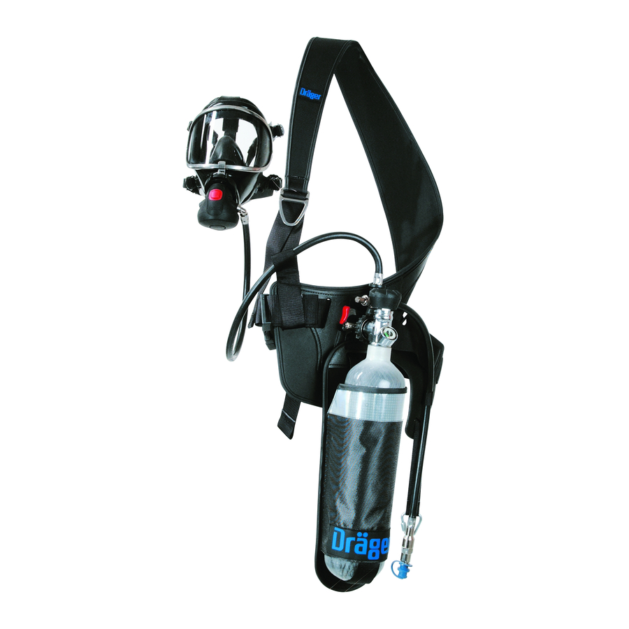
Description and Intended Use
The Dräger PAS Colt Series of Bandolier Airline/Escape equipment
consists of:
●
Bandolier Shoulder Harness with Waist Belt.
●
Pressure Reducer with integral Lung Demand Valve (LDV).
●
Hip Mounted Cylinder Carrying Holster.
●
Airline Manifold Connection – with or without low pressure whistle
warning unit (LPWWU).
●
Valved Cylinder Assembly with Contents Indicator.
The equipment is available in either 10 minute, 15 minute or 20 minute
nominal escape duration versions.
4.1
Optional Variants
●
Pressure Reducer with ChargAir – Direct Filling Assembly.
●
Cylinder Carrying Holster – Drop Down. If applicable, refer to
additional enclosed Instructions for Use.
Important Note: When using equipment fitted with a ChargAir
connection it is necessary to refer to the Use of ChargAir – Direct
Filling instructions supplied with the equipment.
4.2
Accessories
●
Thigh strap
This series of equipment utilises a high performance first stage pressure
reducer in association with an integral lung demand valve. The equipment
is compatible with a range of face mask and compressed air cylinders.
When used in approved carrying system, valved cylinder assembly, LDV
and face mask combinations, the equipment provides the wearer with
respiratory protection when working in, or escaping from a contaminated
or oxygen deficient gaseous atmosphere.
When the airline manifold coupling of the equipment is connected to a
low-pressure independent air supply of breathable air quality, (e.g. Dräger
AirPack System or filtered works airline), then the equipment functions as an
airline working set. In this configuration the cylinder valve of the equipment is
in the closed position. On failure or interruption of the independent air supply
the wearer opens the cylinder valve, disconnects the independent air supply
from the airline manifold connection and then proceeds to escape to a safe
area using the available air supplied from the cylinder.
During escape, the effective duration of the equipment is dependant on the
capacity (volume) of the cylinder selected and the breathing rate of the
wearer.
Safety Warning: When the equipment is worn as an airline working
set then the escape duration starts from the time of opening the
cylinder valve and disconnecting the airline supply. The time
required to allow the wearer to escape to a safe area must be within
the capacity (volume) of the cylinder selected taking into account the
breathing rate of the wearer. When selecting the type and duration of
escape equipment it is essential to consider the potential hazards,
and probable escape routes.
Details of the equipment variants, accessories, and any approved
independent air supply source configurations are available from Dräger on
request.
5
Technical Data
5.1
High Pressure Connections
Standard G5/8 as per EN 144-2.
200bar or 300bar
Important Note: For safety – 300bar units fitted with ChargAir
incorporate a hand wheel connector that will not accept a 200bar
cylinder valve.
Other connections are available to national standards.
5.2
LDV to Face Mask Connection
Three variants of the integral LDV's are available:
3352423
© Dräger Safety UK Limited
Edition 07 – October 2018 (Edition 01 – May 2013)
Subject to alteration
PAS
®
is a registered trade marks of Dräger
1
1583
2
3
4
0016
5
6
1
2
1
5120
7
8
1
●
Push-In Type A – Positive Pressure (PP).
●
Screw-In Type AE – Positive Pressure (PP).
●
Screw-In Type N – Normal Demand (ND).
Refer to the Instructions for Use supplied with the face mask.
5.3
Compressed Air Cylinders
Cylinders are available in either steel, aluminium or composite materials.
Contact Dräger for details.
Cylinders supplied by Dräger are charged at an ambient temperature of
15 °C and to the nominal cylinder pressure – i.e. contents indicator needle
must be aligned with the nominal charged pressure – 200 or 300bar.
5.4
Airline Manifold Connection
A Male Coupling is incorporated on the airline manifold for the connection
of a quick release coupling (QRC) from an independent air supply.
Instructions for Use
5.5
Airline Operating Pressures and Flow
The selected low pressure independent air supply must meet the following
parameters.
●
One User – 6bar to 10bar – airflow rate of at least 550 Litres/minute.
●
Two Users – 7bar to 10bar – airflow rate of at least 550 Litres/minute.
When using an Airline Manifold Connection – with LPWWU, the whistle
activation pressure is preset by Dräger to between 5bar – 4bar.
Safety Warning: Air quality for compressed air breathing systems
must conform to the requirements of EN12021. Do Not use oxygen or
oxygen enriched air.
6
Preparation for Use
A trained and competent person must perform the following checks and
preparation procedures before release of the equipment to a potential
wearer for operational use.
6.1
Visual Inspection
Check the integrity of,
●
Bandolier Shoulder Harness with Waist Belt.
●
Cylinder Carrying Holster.
●
Pressure Reducer, LDV and Hose Assemblies.
●
Airline Manifold Connection and Hose – with or without LPWWU.
●
Face mask – refer to the relevant Instructions for Use.
●
Valved Cylinder Assembly with Contents Indicator.
Optional Variants
●
Cylinder Carrying Holster – Drop Down. Check function of the latching
mechanism.
6.2
Fitting Cylinder
2
●
Check the contents indicator ensuring the cylinder is fully charged, i.e.
1588/1591
contents indicator needle must be aligned with the nominal charged
pressure – 200 or 300 bar.
3
●
Check that the threads of the valve port and the reducer hand wheel
are undamaged, connector O-ring is in position, and undamaged. Fully
2
insert the fully charged cylinder into the carrying Holster.
Caution: To prevent damage, ensure that the hand wheel of the
pressure reducer remains clear of the cylinder.
1
●
Screw the hand wheel of the pressure reducer (clockwise) to the port
of the cylinder valve and tighten the hand wheel – handtight.
Important Note: The following test will verify the integrity of the
1597
complete assembly. The pressure leak test described should also be
carried out following the reassembly of any of the component parts
2
4
6
of the pneumatic assembly (spares etc).
6.3
Pressure Leak Test
●
Again check the contents indicator ensuring the cylinder is fully
charged, i.e. contents indicator needle must be aligned with the
nominal charged pressure – 200 or 300bar.
●
Type A and AE – Press the reset button of the LDV to switch 'Off'
positive pressure.
3
5
●
'Open' the cylinder valve slowly, but fully, to pressurise the system
then 'Close' the valve.
0584
Test Parameters – Check for no audible leak. If necessary, use soap and
water based solution to locate a suspected leak.
Passed Test – Fold the rubber cover from the front of lung demand valve
and press centre of diaphragm to vent pressure from rubber hose and
reducer. Refit the rubber cover.
Type A and AE – Press the reset button of the LDV to switch 'Off' positive
pressure.
Failed Test – Fold the rubber cover from the front of lung demand valve
and press centre of diaphragm to vent pressure from rubber hose and
4961
reducer. Refit the rubber cover. Investigate the source of the leak, rectify
and repeat the test. Until the leak is rectified Do Not release the equipment
for use.
6.4
Leak Test and LP Flow Test – Airline Connection
Refer to Technical Data.
Important Note: If using a works airline to perform the following tests,
then connect the isolation valve (3353449) to the female coupling of
the airline outlet.
●
Connect the male coupling (1) Fig. 2 to the female quick release
coupling (QRC) of the independent air supply.
●
Type A and AE – Press the reset button of the LDV to switch 'Off'
positive pressure.
●
'Open' the valve of the independent air supply to pressurise the
2
system.
Test Parameter – Check for no audible leak.
●
Open' the cylinder valve of the breathing equipment to pressurise the
system, then disconnect the male coupling (1) Fig. 2 from the female
QRC of the hose from the independent air supply.
Test Parameter – Non-return valve check – Check for no audible leak from
3903
the female QRC.
●
'Close' the cylinder valve of the breathing equipment, then reconnect
the male coupling (1) Fig. 2 to the female QRC of the independent air
supply.
●
Fold the rubber cover from the front of lung demand valve and press
centre of diaphragm to activate the airflow from the LDV. Refit the
rubber cover. See Safety Warning.
Safety Warning: Do Not direct the airflow onto the face, eyes or skin.
Test Parameters – An unobstructed airflow should vent from the outlet of
the LDV. This test should take a minimum of 3 to 5 seconds.
●
'Close' the valve of the independent air supply and observe the low
pressure LP gauge, or the high pressure (HP) gauge, if fitted.
Test Parameters
LP Gauge – Indicated pressure should not decrease more than 1bar in
1 minute.
Draeger Safety UK Limited
Ullswater Close
Blyth, NE24 4RG
United Kingdom
Tel +44 1670 352 891
Fax +44 1670 356 266
www.draeger.com
3352423 (A3-D-P) Page 1 of 3
Advertisement

Related Manuals for Dräger PAS Colt Series


Summary of Contents for Dräger PAS Colt Series
- Page 1 When using an Airline Manifold Connection – with LPWWU, the whistle activation pressure is preset by Dräger to between 5bar – 4bar. This variant of the Dräger PAS Colt Series of equipment incorporates a preset and sealed pressure reducer. The associated integral lung demand Safety Warning: Air quality for compressed air breathing systems valve (LDV) has a preset and sealed balanced piston unit assembly.
- Page 2 Safety Warning: Do Not direct the airflow onto the face, eyes or skin. the wearer of the Dräger PAS Colt Series Airline equipment. part of the lung demand valve. ●...
- Page 3 ® Colt Series Instructions for Use Bandolier Airline/Escape compressed air respiratory protection equipment Maintenance and Test Intervals ○ Position the bayonet cap spring in the middle of the diaphragm. Twist the bayonet cap clockwise to fit it to the lung demand valve housing.
Need help?
Do you have a question about the PAS Colt Series and is the answer not in the manual?
Questions and answers