Flowserve Valtek Installation, Operation & Maintenance Instructions Manual
Metal bellows seal valves
Hide thumbs
Also See for Valtek:
Advertisement
Quick Links
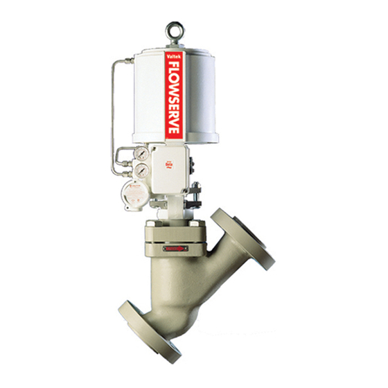
Valtek Metal Bellows
Seal Valves
GENERAL INFORMATION
The following instructions are designed to assist in
disassembling, reassembling and troubleshooting
Valtek valves equipped with a metal bellows seal.
Product users and maintenance personnel should thor-
oughly review this bulletin in conjunction with Mainte-
nance
Instructions 1 (Mark One and Two Control
Valves) before installing, operating or performing any
maintenance on the valve.
This publication does not contain information on Valtek
positioners. Refer to the appropriate Maintenance
Instructions for installing, maintaining, troubleshooting,
calibrating, and operating Valtek positioners.
Three styles of metal bellows seal exist: Guardian,
Guardian II and Formed. Guardian II and Formed
bellows are constructed of flat material, which is rolled
into a tube and then seam welded. The walls of the tube
are then mechanically formed into convolutions.
Guardian bellows are constructed from a series of
matched pairs of metal discs that are welded together.
To avoid possible injury to personnel or dam-
age to valve parts, WARNING and CAUTION
notes must be strictly adhered to. Modifying
this product, substituting non-factory or infe-
rior parts, or using maintenance procedures
other than outlined could drastically affect per-
formance and be hazardous to personnel and
equipment, and may void existing warranties.
Rev. 6/97
Valtek No. 49022
GUARDIAN METAL BELLOWS SEAL
Disassembling Guardian Metal Bellows
Seal
To disassemble the Guardian metal bellows seal, refer
to Figure 1 and proceed as follows:
WARNING: Since toxic or hazardous materials may
be present, depressurize the line to atmospheric
pressure. Drain all process fluids and decontami-
nate the valve. Failure to do so can cause serious
personal injury. Keep hands, hair and clothing
away from moving valve parts at all times. Face and
eye protection should be worn; otherwise, serious
personal injury may occur.
1. Remove bonnet flange bolts and nuts.
2. Remove the entire actuator/bellows seal assembly,
bonnet and bonnet flange by lifting them straight
out of the body.
WARNING: The sleeve may stick to the bellows
seal and fall from the assembly during removal
of the actuator assembly from the body, which
could cause damage or possible injury. To
remove a sticking sleeve, lightly tap on the
sleeve while lifting the actuator assembly.
NOTE: Heavy assemblies may require a hoist. A
lifting ring is provided on most actuators for this
purpose; otherwise, lift by the yoke legs using lifting
straps and a hoist.
12-1
Advertisement

Subscribe to Our Youtube Channel
Related Manuals for Flowserve Valtek


Summary of Contents for Flowserve Valtek
- Page 1 Disassembling Guardian Metal Bellows disassembling, reassembling and troubleshooting Seal Valtek valves equipped with a metal bellows seal. Product users and maintenance personnel should thor- To disassemble the Guardian metal bellows seal, refer oughly review this bulletin in conjunction with Mainte-...
- Page 2 Upper Stem Guide (Item No. 86, 87) Packing Spacers Packing (Item No.s 93 - 99) (Item No. 88) Bonnet Tell-tale Tap (Purge Plug) (Item No. 40) (Item No. 42) Bonnet Flange Bolt Bonnet Flange (Item No. 108, 114) (Item No. 70) Lower Guide Bonnet Gasket (Item No.
- Page 3 8. Remove the bonnet flange, then carefully slide the 10. Apply air pressure above the piston to drive it to the plug/bellows assembly out of the bonnet without bottom of the actuator cylinder. Without rotating the stretching the bellows. Be careful not to lose the anti- plug, back the actuator assembly off of the plug rotation pin from the plug/bellows assembly.
- Page 4 Troubleshooting Guardian Metal Bellows Seals Failure Probable Cause Corrective Action Leakage through 1. Insufficient compression of 1. Tighten bonnet flange bolting until bonnet or sleeve bonnet flange leakage stops gaskets 2. Worn or defective bonnet, sleeve or 2. Disassemble and replace all gaskets, seat ring gasket including seat ring gasket Leakage through...
- Page 5 Actuator / Yoke Assembly Upper Guide (Item No. 86, 87) Packing (Item No. 88) Monitoring Port Packing Spacer (optional) (Item No. 93 - 99) Bellows Seal Housing Tell-tale Tap (Item No. 5) Bonnet Flange Bolting (Item No. 108,114) Shrouded Bellows Assembly (Item No.
- Page 6 4. Place the upper end of the stem into a vice using the stem flats to hold in place. Use caution to not damage the stem or its threads. Thread the plug head into the bellows stem using a wrench on the flats of the head.
- Page 7 then tighten the bolt directly opposite -turn and Table I: Suggested Bonnet Bolting so on around the flange. Firmly tighten all bolts Torque Values (ft-lbs, +10 percent) evenly and completely to compress the bonnet gasket and to seat the bonnet. Torque the bonnet Bolt/Stud Material Bolt bolts to the suggested torque values in Table I.
- Page 8 8. Remove the upper housing clamps or flanges (if 8. Install the stem locknut on the plug stem. Screw separable) and slide the bellows seal bonnet off the plug stem into the bellows seal stem. Proper the bellows seal stem. Care should be taken not to engagement of the plug stem is achieved when lose the anti-rotation pin from the upper seal.
- Page 9 Packing Spacers (Item No. 93 - 99) Tell-tale Tap Bellows Seal Bonnet Upper Housing Bolt (Item No. 7) (Item No. 106) Upper Seal Ring Gasket "B" (Item No. 59) Upper Seal Ring Gasket "A" (Item No. 59) Bellows Seal Housing (Item No.
- Page 10 Anti-rotation Pin (Refer to Step 8 in "Reassembly" Section) Bellows Seal Assembly Spring Guide Retainer should compres approximately 1/ 8-inch Plug Stem Jam Nut Stroke + 1/ 16-inch Bellows Seal Plug 1-inch to less stroke stroke +1/ 32-inch (See Table II) Figure 5: Plug Thread Adjustment 12-10...
- Page 11 Table II: 19. Install the entire actuator/bellows seal subassem- bly into the valve body. Tighten the bonnet flange Extended Plug to Bonnet Dimensions bolting finger-tight. (refer to Figure 5) 20. Apply air pressure over the piston while exhausting Valve Size Stroke Distance Between the other side to seat the valve.
- Page 12 Valtek will continue to provide its customers with the best possible products and service available. Should you have any questions about these provisions or about Valtek's products in general, contact your local Valtek representative or the factory directly for assistance.
Need help?
Do you have a question about the Valtek and is the answer not in the manual?
Questions and answers