Advertisement
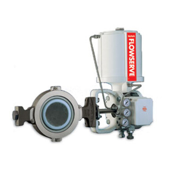
Valtek Valdisk
Control Valves
GENERAL INFORMATION
The following instructions are designed to assist in
unpacking, installing and performing maintenance as
required on Valdisk rotary valves. Product users and
maintenance personnel should thoroughly review this
bulletin prior to installing, operating, or performing any
maintenance on the valve.
Separate maintenance instructions cover additional
features (such as actuators, positioners, special acces-
sories, fail-safe systems, etc.) Refer to the appropriate
Flowserve Installation, Operation, Maintenance Instruc-
tions when information on installing, maintaining, trou-
bleshooting, calibrating, and operating Valtek
tors or positioners is required.
To avoid possible injury to personnel or damage
to valve parts, WARNING and CAUTION notes
must be strictly adhered to. Modifying this
product, substituting nonfactory parts, or using
maintenance procedures other than outlined
could drastically affect performance, be
hazardous to personnel and equipment, and
may void existing warranties.
WARNING: Standard industry safety practices must
be adhered to when working on this, or any other,
process control product. Specifically, personal
protective and lifting devices must be used as
warranted.
Valtek No. 49020
NOTE: Selecting the proper fastener material is the
responsibility of the customer. Typically, the supplier
does not know what the valve service conditions or
environment may be. Valtek's standard body bolting
material is B7/2H. B8 (stainless steel) is optional for
applications above 800 ° F and with stainless steel or
alloy body valves. The customer therefore must consider
the material's resistance to stress corrosion cracking in
addition to general corrosion. As with any mechanical
equipment, periodic inspection and maintenance is
required.
materials, contact your local Valtek representative or
®
actua-
factory.
Unpacking
1. While unpacking the valve, check the packing list
against the materials received. Lists describing the
valve and accessories are included in each ship-
ping container.
2. When lifting the valve from the shipping container,
position lifting straps to avoid damage to tubing and
mounted accessories. Valves up through 14-inch
may be lifted by the actuator lifting ring. On larger
valves, lift the valve using lifting straps or hook
through the yoke legs and outer end of the body.
3. In the event of shipping damage, contact your
shipper immediately.
4. Should any problem arise, contact your Valtek
representative.
For more information about fastener
10-1
Advertisement
Table of Contents

Related Manuals for Flowserve Valtek Valdisk


Summary of Contents for Flowserve Valtek Valdisk
- Page 1 As with any mechanical sories, fail-safe systems, etc.) Refer to the appropriate equipment, periodic inspection and maintenance is Flowserve Installation, Operation, Maintenance Instruc- required. For more information about fastener tions when information on installing, maintaining, trou-...
-
Page 2: Installation
Table I: Flange Bolting Torques WARNING: Keep hands, hair, clothing, etc. away from the rotating disc and the seat when Valve Rating Torque operating the valve. Failure to do so could Size (inches) (ft./lbs.) cause serious injury. CAUTION: Because of Valdisk’s self-centering seat, there is no reason to open the valve at any time during installation. -
Page 3: Preventive Maintenance
the air supply or disconnect the instrument signal. 8. Remove transfer case cover plate and make sure By observing the indicator plate, the disc should the positioner linkage and internal actuator parts either fail open or closed. If incorrect, refer to the are securely fastened. - Page 4 Taper Pins (Item No. 52) Disc Body (Item No. 50) Shaft Bearing (Item No. 83) (Item No. 1) Shaft Seat Shaft (Item No. 51) Plug (Item No. 122) Inner Packing (Item No. 88) Outer Packing (Item No. 88) Packing Follower (Item No.
- Page 5 Standard Square Standard Single "V" Twin "V" Twin "V" with Lubricator SafeGuard SureGuard SafeGuard / SureGuard Fire-safe Option (packing studs rotated 45 degrees) (live-loading omitted) Figure 3: Typical Packing Configurations side of the disc and insert the shaft through the 7.
- Page 6 Right-hand Mounting Facing Downstream Style A Fail-closed Air-to-open Shaft Upstream Style B Fail-open Air-to-close Shaft Upstream NOTE: Styles B and D may require a heavy-duty spring to achieve failure. Style C Fail-open Air-to-close Shaft Downstream Style D Left-hand Mounting Fail-closed Air-to-open Facing Downstream Shaft Downstream...
- Page 7 body with the open ends of the snap-ring in the rotation of the disc, marks provided on the end of the body groove. Gently press the snap-ring into the shaft and on the lever arm should be aligned. retainer until both the retainer and snap-ring slip 2.
- Page 8 Flowserve Corporation has established industry leadership in the design and manufacture of its products. When properly selected, this Flowserve product is designed to perform its intended function safely during its useful life. However, the purchaser or user of Flowserve products should be aware that Flowserve products might be used in numerous applications under a wide variety of industrial service conditions.
Need help?
Do you have a question about the Valtek Valdisk and is the answer not in the manual?
Questions and answers