Advertisement
Quick Links
Advertisement

Related Manuals for Redarc Tow-Pro Trail


Summary of Contents for Redarc Tow-Pro Trail
- Page 1 Tow‑Pro Trail ® Electric Trailer Brake Controller 12 V or 24 V, 1–3 Axles MODEL: EBRH‑ACCV3‑NA‑T ƒ...
- Page 2 Tow‑Pro Trail ® Electric Trailer Brake Controller (EBRH‑ACCV3‑NA‑T) The Tow‑Pro Trail is an electric trailer brake controller designed to suit most common trailer braking applications. It requires minimal dash space and is simple to install and operate. The Tow‑Pro Trail has selectable Everyday or Manual Off‑road trailer braking modes that allow you to choose the braking style depending on the road or terrain conditions, vehicle type, or driver preference.
- Page 3 CONTENTS 1 WARNINGS AND SAFETY INSTRUCTIONS ��������������������������������������������������������������������� 2 KIT CONTENTS �������������������������������������������������������������������������������������������������������������������� 3 INSTALLATION ��������������������������������������������������������������������������������������������������������������������� Mounting the Main Unit ��������������������������������������������������������������������������������������������������� Wiring the Brake Controller ���������������������������������������������������������������������������������������������� Mounting the Remote Head������������������������������������������������������������������������������������������� 4 OPERATION ����������������������������������������������������������������������������������������������������������������������� Active Calibration ���������������������������������������������������������������������������������������������������������� Adjusting the Braking Force ������������������������������������������������������������������������������������������� SwayStop ���������������������������������������������������������������������������������������������������������������������...
- Page 4 Electric Trailer Brake Controller. Do not operate the controller unless you have read and understood this manual and the controller is installed as per these installation instructions. REDARC recommends that the controller be installed by a suitably qualified person. SAFETY MESSAGE CONVENTIONS...
- Page 5 11. During the calibration step of the Tow‑Pro, braking of the trailer may be inconsistent. REDARC recommends calibrating the Tow‑Pro without a trailer attached. A normal drive of a few miles will do for this purpose. If calibrating with a trailer attached, then the recommended setting for the Tow‑Pro is 4 or less.
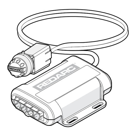
- Page 6 KIT CONTENTS Reference Description Remote Head Assembly Main Unit Remote Head Nut Remote Head Control Knob Remote Head Bezel Remote Head Cable 3'3" (1 m) Main Unit Wires and Connector 1'7" (0.5 m) Tow‑Pro Universal Switch Insert Panel 6 | Kit Contents...
- Page 7 INSTALLATION 3.1 MOUNTING THE MAIN UNIT The Tow‑Pro Trail should be mounted inside the vehicle cabin using either 5/32" (M4) diameter screws or other secure fitting methods at the mounting points provided. It is essential to mount the unit in a location which allows access to the intended remote head location.
- Page 8 REDARC Electronics manufactures a number of vehicle‑specific wiring harnesses for quick and easy installation (refer to REDARC’s website for details). The universal wiring harness included with the EBRH‑ACCV3‑NA‑T kit is the TPH‑025 ‘Universal Harness’ which is typically used for older vehicles not covered by our range of wiring harnesses.
- Page 9 WIRING — ELECTRIC BRAKES For 12 V and 24 V vehicle electrical systems, the Tow‑Pro Trail is designed to operate electric brakes without the need for any additional converters. For wire selection refer to "Wiring Gauge Guide" on page 12 AWG 25 A Fuse (3 mm ) To 12 V Electric INPUT...
- Page 10 WIRING — ELECTRIC/HYDRAULIC BRAKES NOTICE Always refer to the manufacturer’s specifications for your Electric/Hydraulic Braking system prior to installation and usage of the Tow‑Pro Trail. 12 V VEHICLE SYSTEMS The Tow‑Pro Trail is designed to operate both Electric trailer brake systems and 12 V Electric/Hydraulic trailer brake systems.
- Page 11 Many modern vehicles use a CAN Bus system for signalling when to apply the vehicles brakes as required by safety systems including adaptive cruise control, stability control, Autonomous Emergency Braking (AEB) and hill descent control. For these vehicles, REDARC recommend the following wiring configuration. To 12 V Electric...
- Page 12 INSTALLATION ACCESSORIES REDARC offer a range of vehicle specific switch inserts and vehicle specific wiring kits designed to make the installation of the Tow‑Pro Trail easier.
- Page 13 MOUNTING THE REMOTE HEAD ON A DASH OR CONSOLE PANEL Ensure that there is enough space behind the mounting location to fit the Tow‑Pro Main Unit and remote head cable before drilling any holes. CAUTION • Ensure the remote head push‑button activates correctly when installed into panels thicker than ⁄...
- Page 14 OPERATION 4.1 ACTIVE CALIBRATION When the unit is first powered, Active Calibration must first become confident in the vehicle direction of travel. Until this time the LED will flash Blue/Green. During Calibration Once Calibrated Time Time Active Calibration constantly monitors the vehicle’s direction of travel and allows the Tow‑Pro Trail to ‘learn’ and continuously confirm its mounting orientation.
- Page 15 4.3 SWAYSTOP Pressing the Control Knob whilst driving activates SwayStop, applying the manual override brake. SwayStop will apply the trailer brakes only, and will also apply the trailer brake lights and will turn the LED indicator RED. Depending on the vehicle wiring it may also apply the vehicle brake lights. SwayStop is designed to be used when the trailer brakes need to be applied without the vehicle brakes, such as correcting trailer ‘sway’...
- Page 16 CHANGING MODES Changing modes can only be completed with a trailer connected. Ensure the vehicle has come to a complete stop before beginning the mode change process. Changing between modes requires the user to complete the following process: 2× 1. Rotate the knob fully 2.
- Page 17 4.7 LED INDICATION The Tow‑Pro Trail will indicate both Mode and Fault Condition through color and flash sequences of the LED indicator. The table shows how the Tow‑Pro Trail will indicate Operation of the unit. NOTE: LEDs will glow full brightness when the Control Knob is adjusted or pressed. After release of the Control Knob the LED brightness will reduce.
- Page 18 Reconnect the trailer plug, then confirm that the Tow‑Pro is functioning correctly. Check that the Control Knob LED is on, and you are able to change modes. Test the SwayStop function shortly into your initial trip. If there is no trailer braking, stop towing and contact the REDARC technical support team for assistance. Tether (vehicle side)
- Page 19 Start up fault (usually after persists, do a Hard Reset* and contact (no change of LED color when connecting the trailer) REDARC for further assistance brake applied) Check trailer plug pin tension and Intermittent open circuit or 1 Second The LED is YELLOW and...
- Page 20 (WHITE wire) 1 Second The LED is flashing GREEN Do a Hard Reset* or contact REDARC Loss of supply power only whilst braking for further assistance Hesitation during connection of 1 Second The LED is flashing GREEN at...
- Page 21 It is important to have a qualified technician check the function of your trailer system on a periodic basis to ensure that everything is operating correctly. REDARC recommends that you visit a qualified technician before the beginning of each holiday season to ensure that any towing aids or systems are working correctly.
- Page 22 SPECIFICATIONS Part Number EBRH‑ACCV3‑NA‑T Operating Voltage 9 V to 32 V Nominal Input System Voltage 12 V 24 V OFF: 0 V OFF: 0 V Brake Input Signal Voltage ON: +12 V nominal ON: +24 V nominal Brake Coil Voltage 12 V Max. Trailer Axles 3 Axles Nominal Current Draw 18 A Max.
- Page 23 COMPLIANCE 8.1 FCC DECLARATION This device complies with part 15 of the FCC Rules. Operation is subject to the following two conditions: (1) This device may not cause harmful interference, and (2) this device must accept any interference received, including interference that may cause undesired operation Note: This equipment has been tested and found to comply with the limits for a Class B digital device, pursuant to part 15 of the FCC Rules.
- Page 24 FREQUENTLY ASKED QUESTIONS My trailer is 3.5 tonnes fully loaded; Is the Tow‑Pro Trail strong enough to stop that much weight safely? The controller is capable of supplying 3‑axle setups at 12 V or 24 V inputs up to the maximum rated braking ability of the brakes.
- Page 25 MONTH of manufacture, in the format YYMM. Design and specifications are subject to change without notice� | Copyright © REDARC Electronics Pty Ltd� All rights reserved� REDARC®, THE POWER OF REDARC®, and Tow‑Pro® are trademarks of REDARC Electronics Pty Ltd�...
- Page 26 NOTES...
- Page 28 Tech Support 1300 REDARC (1300‑733‑272) Australia +61 8 8322 4848 New Zealand +64 9 222 1024 UK & Europe +44 (0)20 3930 8109 +1 (704) 247‑5150 Canada +1 (604) 260‑5512 Mexico +52 (558) 526‑2898 redarcelectronics.com INST321‑1 EN...
Need help?
Do you have a question about the Tow-Pro Trail and is the answer not in the manual?
Questions and answers
Will it work with a bad ground , how do you check to know if it's bad and if not