Table of Contents
Advertisement
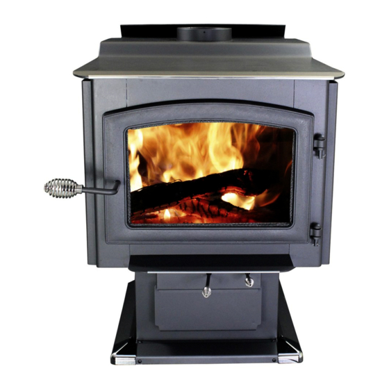
Owner's Instruction and Operation Manual
Model Number:
VG3200-P
Report Number: F20-586
Tested Per EPA Methods ALT-125, ASTM
E2515, ASTM E3053 and CSA B415
Certified to UL 1482-2011 (R2015) and
ULC-S627-00-REV1
Approved for mobile home installation in
(USA ONLY)
* All Pictures In This Manual Are For Illustrative Purposes Only. Actual Product May Vary.
Save These Instructions In A Safe Place For Future Reference.
SAFETY NOTICE: If this heater is not properly installed, a house fire may result. For
your safety, follow the installation instructions. Never use make-shift compromises
during the installation of this heater. Contact local building or fire officials about
permits, restrictions and installation requirements in your area. NEVER OPERATE THIS
PRODUCT WHILE UNATTENDED.
CAUTION! Please read this entire manual before you install or use your new room
heater. Failure to follow instructions may result in property damage, bodily injury, or
even death. Improper Installation Will Void Your Warranty!
U.S. Environmental Protection Agency
Certified to comply with 2020 particulate
emissions standards.
© 2021 United States Stove Company, 227 Industrial Park Rd., South Pittsburg, TN 37380
R
THIS MANUAL IS SUBJECT TO CHANGE WITHOUT NOTICE.
CALIFORNIA PROPOSITION 65 WARNING:
This product can expose you to chemicals
including carbon monoxide, which is known to the
State of California to cause cancer, birth defects,
and/or other reproductive harm. For more
information, go to
853745E-1805K
www.P65warnings.ca.gov
Ph. 800-750-2723
Advertisement
Table of Contents

Related Manuals for Vogelzang International VG3200-P


Summary of Contents for Vogelzang International VG3200-P
- Page 1 Owner’s Instruction and Operation Manual Model Number: VG3200-P Report Number: F20-586 Tested Per EPA Methods ALT-125, ASTM E2515, ASTM E3053 and CSA B415 Certified to UL 1482-2011 (R2015) and ULC-S627-00-REV1 Approved for mobile home installation in (USA ONLY) * All Pictures In This Manual Are For Illustrative Purposes Only. Actual Product May Vary.
- Page 2 INTRODUCTION The instructions pertaining to the installation of your wood stove comply with UL-1482 (R2015) and ULC-S627 standards. This manual describes the installation and operation of the Vogelzang, VG3200 wood heater. This heater meets the 2020 U.S. Environmental Protection Agency’s cordwood emission limits for wood heaters sold after May 15, 2020. Under specific test conditions this heater has been shown to deliver heat at rates ranging from 19,778 to 67,992 Btu/hr with 1.3 g/hr and 71% efficiency.
-
Page 3: Installation Checklist
INSTALLATION CHECKLIST Your Wood Stove should be installed by a qualified installer only. An NFI qualified Installer can be found at www.nficertified. org/public/find-an-nfi-pro/ CUSTOMER SERVICE 1-800-750-2723 ext 5050 Text to 423-301-5624 Email to: Customerservice@usstove.com COMMISSIONING CHECKLIST This Checklist is to be completed in full by the qualified person who installs this unit. Keep this page for future reference. Failure to install and commission according to the manufacturer’s instructions and complete this checklist will invalidate the warranty. -
Page 4: Blower Assembly
ASSEMBLY INSTRUCTIONS FOR CUSTOMER SERVICE CALL: 800-750-2723 EXT 5050 BLOWER ASSEMBLY PEDESTAL BASE ASSEMBLY The blower assembly must be disconnected from 1. Assemble the pedestal base skirting. Attach two the source of electrical supply before attempting the corner pieces (A) to the center section (B) of skirting installation. -
Page 5: Installation
ASSEMBLY INSTRUCTIONS FIREBRICK CONFIGURATION 3. Slide the U-shaped skirting assembly around the pedestal base and secure with two 1/4” long pan head Replace the Firebrick as shown in the illustration. sheet metal screws at the rear corners. INSTALLATION SAFETY NOTICE •... -
Page 6: Floor Protector
INSTALLATION FLOOR PROTECTOR This heater must have a non-combustible floor protector with an R-Value of at least 1.2 installed beneath it if the floor is constructed of combustible material. If a floor pad is used, it should be UL listed or equal. The floor protector should be large enough to extend under the stove and beyond each side as indicated. -
Page 7: Chimney Connector (Stove Pipe)
INSTALLATION 4. The house is equipped with a well-sealed vapor barrier In addition to the previously detailed installation and tight fitting windows and/or has any powered requirements, the heater must be electrically grounded to devices that exhaust house air. the steel chassis of the mobile home with 8 GA copper wire using a serrated or star washer to penetrate paint or 5. -
Page 8: Importance Of Proper Draft
INSTALLATION IMPORTANCE OF PROPER DRAFT 3. The installation of an interior chimney is always preferable to an exterior chimney. Indeed, the interior Draft is a force that moves air from the appliance up chimney will, by definition, be hotter than an exterior through the chimney. -
Page 9: Masonry Chimney
INSTALLATION and install the ceiling support package or wall pass- Wall Member: Using a minimum thickness 3.5” (89 mm) through and “T” section package, firestops (where needed), brick and a 5/8” (16 mm) minimum wall thickness clay insulation shield, roof flashing, chimney cap, etc. Maintain liner, construct a wall pass-through. - Page 10 INSTALLATION METHOD C - 6” (153 mm) Clearance to Combustible Use this as a pass-through for a minimum 24-gauge single Wall Member: Starting with a minimum 24 gage (.024” wall steel chimney connector. Keep solid-pak section [.61 mm]) 6” (153 mm) metal chimney connector, and a concentric with and spaced 1”...
- Page 11 OPERATION INSTRUCTIONS NEVER OPERATE THIS PRODUCT WHILE UNATTENDED lower emissions generally result when burning air dried OPERATING SAFETY PRECAUTIONS seasoned hardwoods, as compared to softwoods or too • NEVER OVERFIRE THIS APPLIANCE BY BUILDING green or freshly cut hardwoods. The following resources EXCESSIVELY HOT FIRES AS A HOUSE/BUILDING can assist in learning the burn characteristics of various FIRE MAY RESULT.
-
Page 12: Testing Your Wood
OPERATION INSTRUCTIONS is EXTREMELY IMPORTANT that you use DRY WOOD only regulations to alter this setting or otherwise operate this in your wood stove. The wood should have dried for 9 to wood heater in a manner inconsistent with operating 15 months, such that the humidity content (in weight) instructions in this manual. - Page 13 OPERATION INSTRUCTIONS meet strict 2020 guidelines. To ensure this unit produces setting. For a medium burn, once the high burn fuel load is the optimal minimum emissions it is critical that only burned down to an established coal bed, load the unit with well-seasoned cordwood is burned (see the “Fuel 31 to 32 lbs of cordwood and keep the door slightly open Recommendations”...
- Page 14 OPERATION INSTRUCTIONS VISIBLE SMOKE HEARTH The amount of visible smoke being produced can be an effective method of determining how efficiently the OPEN OPEN CONTROL CONTROL combustion process is taking place in the given settings. LEVER LEVER Visible smoke consists of unburned fuel and moisture leaving your stove.
-
Page 15: Chimney Maintenance
CHIMNEY MAINTENANCE NEVER OPERATE THIS PRODUCT WHILE UNATTENDED • Always check for creosote deposit once every two CAUTION: months and have your chimney cleaned at least once DO NOT OVERFIRE APPLIANCE. YOU ARE OVERFIRING a year. IF ANY PART OF THE APPLIANCE GLOWS RED. CLOSE •... -
Page 16: Glass Care
CHIMNEY MAINTENANCE and chimney joints are in good working order and sealing wood stoves are sold. The glass should be washed only properly to ensure unintended exposure. It is recommended when cold. that you use both smoke and CO monitors in areas having GASKET CARE the potential to generate CO. -
Page 17: Repair Parts
REPAIR PARTS Part # Description 40597 Skirt Corner 892268 Heat Shield (Left) 26546 Front Skirt 892269 Heat Shield (Rear) 26553 Right Side Skirt 892267 Heat Shield (Right) 69911 Pedestal 892278 Top Trim To order parts: 892279 Hearth Trim Call 1-800-750-2723 Ext 5051 or 69912 Ash Drawer Email to: parts@usstove.com... - Page 18 REPAIR PARTS Part # Description 88194 C-Cast Bottom 892280 Notched Firebrick 891414 Half Firebrick 89066 Firebrick (4-1/2 X 9) 892281 1.5” Firebrick 40595 Half Brick Ash Plug 86698 Tube(1), Secondary Air Tube (4mm) 86699 Tube(2,3), Secondary Air Tube (3mm) 86700 Tube(4), Secondary Air Tube (2.5mm) 86701 Tube(5), Secondary Air Tube (2.0mm)
-
Page 19: Wiring Diagram
WIRING DIAGRAM DANGER: SHOCK HAZARD. DISCONNECT POWER SOURCE BEFORE INSTALLATION AND WHENEVER SERVICING BLOWER ASSEMBLY. CAUTION: MOVING PARTS CAN CAUSE INJURY. DO NOT OPERATE WITH COVER REMOVED. Black White Black Black Black Black Blower Blower Rheostat Motor Blower Specs: Attach Ground 110, 60 Hz AC, Green White... -
Page 20: Service Record
SERVICE RECORD It is recommended that your heating system is serviced regularly and that the appropriate Service Interval Record is completed. SERVICE PROVIDER Before completing the appropriate Service Record below, please ensure you have carried out the service as described in the manufacturer’s instructions.