Table of Contents
Advertisement
Quick Links
Installation/Operator's Manual
SAVE THESE INSTRUCTIONS
U.S. Environmental Protection Agency
Certified to comply with 2015 particulate emissions standards.
Certifi ed for installations in the USA.
Safety Tested to UL 391-2010
Model: VG7100
Wood or Coal Gravity Style (Up-Flow) Central or Supplemental Furnace (USA)
Stand-Alone Central Furnace for Canadian installations
SAFETY NOTICE:
If this furnace is not properly installed, a house fi re may result! For your safety, follow these installation instructions. Contact
local building or fi re offi cials about restrictions and installation requirements in your area. Th is furnace must be installed by a
qualifi ed technician. Keep these instructions for future reference.
United States Stove Company • 227 Industrial Park Road, P.O. Box 151 • South Pittsburg, TN 37380 • www.vogelzang.com
852063C-1909E
Advertisement
Table of Contents

Subscribe to Our Youtube Channel
Related Manuals for Vogelzang International VG7100


Summary of Contents for Vogelzang International VG7100
- Page 1 Certified to comply with 2015 particulate emissions standards. Certifi ed for installations in the USA. Safety Tested to UL 391-2010 Model: VG7100 Wood or Coal Gravity Style (Up-Flow) Central or Supplemental Furnace (USA) Stand-Alone Central Furnace for Canadian installations SAFETY NOTICE: If this furnace is not properly installed, a house fi re may result! For your safety, follow these installation instructions.
-
Page 2: Disclaimer Notice
INTRODUCTION LOCATING YOUR FURNACE Thank You for your purchase of a Vogelzang Wood/Coal The furnace is to be installed maintaining the clearances Burning Gravity Style (Up-Flow) Furnace. Your decision specifi ed in the following illustrations. to buy our Furnace was undoubtedly reached after much Do not place the furnace directly on a combustible fl... -
Page 3: Importance Of Proper Draft
Insulated Chimney must be used in all airtight wood fur- nace installations. The minimum recommended fl ue size CREOSOTE - FORMATION AND NEED for the model VG7100 is 6 inches, inside diameter. When FOR REMOVAL making new chimney installations, always follow the chim- ney manufacturer’s instructions. - Page 4 24 Gauge or Heavier 18” feet. If it is absolutely necessary to make a run of more than six feet (not recommended) use extra support Single Wall Stainless Steel brackets every 3 feet. or Black Pipe 4. The connector pipe should never be reduced to a Double Wall, Stainless Steel or 6”...
-
Page 5: Installation Examples
reasonably safe and functional installation IF certain stan- 3. All larger furnaces (or those with multi-speed blowers) dard procedures are followed. The following are guide- absolutely require BACK PRESSURE to prevent pre- lines only and are intended to enable the furnace user to mature motor winding failure. -
Page 6: Combustion Air
THE PLENUM OPENINGS DIFFER BETWEEN THE 1602 AND 1802 PLENUM OPENING MODEL 1602 - 13” x 18” Rectangular MODEL 1802 - 18” x 18” Rectangular RETURN AIR IS VERY IMPORTANT When installing a Furnace, return air MUST BE incorpo- rated into the system. Return air can be provided by in- stalling a separate duct system or by tying into the cold air return of an existing gas or oil furnace. -
Page 7: Door Handles
FURNACE ASSEMBLY INSTRUCTIONS SHAKER GRATE HANDLE Unpack your Furnace and insure that there is no ship- ping damage. If damage exist, please contact your deal- Insert the Shaker Rod into the hole on the ash door frame er immediately. Your furnace will require some assembly as shown. - Page 8 SPIN DAMPER two of the #10 x 1/2 screws provided. Install the 5 x 5 insulation between the cabinet back and junction Screw the spin draft onto the 3/8” x 2-1/2” carriage bolt box, with the foil side to the cabinet back. Attach the followed by the 3/8”-16 lock nut.
-
Page 9: Wiring Diagram
WIRING DIAGRAM All electrical connections should be done by a qualifi ed electrician. NOTE: The extra brown wire on the fan center has no use. It should be capped off or removed. The conduit may be cut shorter to provide a cleaner installation. -
Page 10: Starting A Wood Fire
TESTING AND OPERATING PROCEDURES GENERAL FURNACE OPERATION 10. Salt water driftwood or other previously salt water sat- urated materials; When you start a fi re in the furnace and it reaches operat- 11. Unseasoned wood; or ing temperature, the blower(s) will come on automatically. The snap-disc is adjustable from 100°F(A) to 140°F(E), 12. -
Page 11: Starting A Coal Fire
STARTING A WOOD FIRE over height of fi rebrick. This can result in damage to your furnace and home. Using Forced Air Draft (optional) 4. Close by-pass damper. Shut off FAD when fuel door is open • Too much draft air will cause clinkering of coal and will 1. - Page 12 • The furnace is designed to burn air dried wood and 1. Any air fi lter should be removed. coal at a predetermined fi ring rate. Over fi ring could 2. Observe the furnace operation closely and often till result in damage to the heat exchanger and cause power is restored.
-
Page 13: Over Firing
calculated using the lower heating value of wood will be ney, exposure to the gases in closed or confi ned areas can higher than effi ciency calculated using the higher heat- be dangerous. Make sure you stove gaskets and chimney ing value. -
Page 14: Trouble Shooting And Problem Solving
TROUBLE SHOOTING AND PROBLEM SOLVING 1. Problem: Distribution blower vibrating Smoke puffs from furnace Solution: Solution: A. Tighten blower wheel to motor shaft. A. Check chimney draft. Check for blocked chimney or fl ue B. Check for bad fan bearings. pipe. -
Page 15: Stove Operation
BULLETIN RC454 A GUIDE TO BURNING COAL IN YOUR FURNACE Furnaces that are capable of burning coal usually will burn smoke. As the gases burn off the fl ames become shorter, both Bituminous and Anthracite coal. Anthracite is perhaps change color and produce less smoke. the best coal fuel because of its long even burn time, high Once the fi... - Page 16 BULLETIN RC454 A GUIDE TO BURNING COAL IN YOUR FURNACE BANKING THE FIRE ing will have to take place with each particular setting of all dampers and controls as the chimney provides the draft For extended operation, such as overnight, the fi re will necessary to not only exhaust the smoke, but to pull com- need to be banked.
-
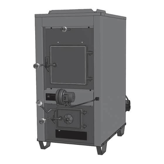
Page 17: Parts Diagram
PARTS DIAGRAM... -
Page 18: Parts Diagram And List
PARTS DIAGRAM AND LIST Description Part # Description Part # Feed Door Assy. (w/Rope Gasket) 69091 Snap-disc Box 68234 Door Handle 24179 Conduit Assembly (1.5ft) 68231 Lock Nut, 1/2-13 83444 Junction Box 25625 Washer 83835 Insulation (5” x 5”) 25626 Spring Handle 89574 Junction Box Cover... - Page 19 16DIKL FORCED DRAFT BLOWER - OPTIONAL KIT USSC offers a forced induced draft blower kit as an op- tion to upgrade your furnace. Advantages of the forced draft are quicker recovery and greater turbulence inside the fi rebox for better mixing of fuel and oxygen. And, it also allows you the furnace to be thermostatically con- trolled.
- Page 20 DOMESTIC HOT WATER COIL KIT - OPTIONAL This Furnace will accept the installation of a Domestic Hot Water Coil Kit. The Vogelzang kit is a 1124 Water Coil and it may be purchased from your local dealer. 1. Remove the access panel on the rear of the furnace enclosure.
- Page 21 NOTES...
- Page 22 NOTES...
- Page 23 NOTES...
-
Page 24: How To Order Repair Parts
When placing an order or for warranty claims, please provide the following information found on the Certifi cation Plate located below the ash door. PART NUMBER PART DESCRIPTION MODEL NUMBER - VG7100 SERIAL NUMBER______________ United States Stove Company 227 Industrial Park Road P.O.
Need help?
Do you have a question about the VG7100 and is the answer not in the manual?
Questions and answers