
Related Manuals for Meinberg LANTIME M400/GPS


Summary of Contents for Meinberg LANTIME M400/GPS
- Page 1 TECHNICAL REFERENCE LANTIME M400/GPS 1st March 2021 Meinberg Funkuhren GmbH & Co. KG...
-
Page 3: Table Of Contents
2.11 Return of Electrical and Electronic Equipment ......3 Global Information LANTIME M400/GPS 4 Technical Specifications LANTIME Chassis... -
Page 4: Imprint
1 Imprint 1 Imprint Meinberg Funkuhren GmbH & Co. KG Lange Wand 9, 31812 Bad Pyrmont / Germany Phone: + 49 (0) 52 81 / 93 09 - 0 Fax: + 49 (0) 52 81 / 93 09 - 230 Internet: https://www.meinbergglobal.com... -
Page 5: Important Safety Information
Meinberg Funkuhren shall not be responsible for any damage arising due to non-observance of these regulations. -
Page 6: Used Symbols
2 Important Safety Information 2.2 Used Symbols The following symbols and pictograms are used in this manual. To illustrate the source of danger, pictograms are used, which can occur in all hazard classes. Symbol Beschreibung / Description IEC 60417-5031 Gleichstrom / Direct current IEC 60417-5032 Wechselstrom / Alternating current IEC 60417-5017... - Page 7 The manuals for a product are included in the scope of delivery of the device on a USB stick. The manuals can also be obtained via the Internet. Enter www.meinbergglobal.com into your browser, then enter the correspond- ing device name in the search field at the top. This manual contains important safety instructions for the installation and operation of the device.
-
Page 8: Security During Installation
2 Important Safety Information 2.3 Security during Installation WARNING! Preparing for Commissioning This built-in unit, has been designed and examined according to the requirements of the standard IEC 62368-1 "Audio/video, information and communication technology equipment - Part 1: Safety requirements". When the built-in unit is used in a terminal (e.g., housing cabinet), additional requirements according to Standard IEC 62368-1 must be observed and complied with. - Page 9 Connecting Data Cables During a thunderstorm, data transmission lines must not be connected or disconnected (risk of lightning). When wiring the devices, the cables must be connected or disconnected in the order of the arrangement described in the user documentation accompanying the device. Always attach all cables to the plug during connection and removal.
- Page 10 2 Important Safety Information AC Power Supply DC Power Supply The device is a device of protection Outside the assembly group the device must be • • class 1 and may only be connected to a disconnectable from power supply grounded outlet (TN system).
-
Page 11: Protective Conductor- / Ground-Terminal
2.4 Protective Conductor- / Ground-Terminal ATTENTION! In order to ensure safe operation and to meet the requirements of IEC 62368-1, the device must be correctly connected to the protective earth conductor via the protective earth connection terminal. If an external earth connection is provided on the housing, it must be connected to the equipotential bonding rail (grounding rail). -
Page 12: Fuse Replacement
2 Important Safety Information 2.5 Fuse Replacement WARNING! This equipment is operated at a hazardous voltage. Danger to life due to electrical shock! Disconnect the device from the mains! To do this, press the disconnector (switch). Then, loosen the locking screws of the supply plug (if present) and pull it off. -
Page 13: Safety During Operation
2.6 Safety during Operation WARNING! Avoiding Short-Circuits Make sure not to get any objects or liquids inside the unit. Electric shock or short circuit could result. Ventilation Slots Make sure that the ventilation slots are not covered or dusty, as there is a danger of overheating during operation. -
Page 14: Safety During Maintenance
2 Important Safety Information 2.7 Safety during Maintenance WARNING! When you are expanding the device, use only device parts that are approved for the system. Non-observance may result in injury to the EMC or safety standards and cause malfunction of the device. If device parts, which are released for the system, are extended or removed there may be a risk of injury in the area of the hands, due to the pull-out forces (approx. -
Page 15: Cleaning And Care
2.9 Cleaning and Care ATTENTION! Do not wet clean the appliance! Penetrating water can cause considerable dangers to the user (e.g., electric shock). Liquid can destroy the electronics of the device! Liquid penetrates into the housing of the device and can cause a short circuit of the electronics. Only clean with a soft, dry cloth. -
Page 16: Return Of Electrical And Electronic Equipment
Return and Collection Systems For returning your old equipment, please use the country-specific return and collection systems available to you or contact Meinberg. The withdrawal may be refused in the case of waste equipment which presents a risk to human health or safety due to contamination during use. -
Page 17: Global Information Lantime M400/Gps
3 Global Information LANTIME M400/GPS LANTIME stands for Local Area Network Timeserver. The LANTIME provides an absolute and highly precise time reference in a TCP/IP network (stratum 1 server). The time is made available to all NTP clients by NTP protocol (Network Time Protocol) and allows a simple integration of an absolute time reference into an existing network. -
Page 18: Technical Specifications Lantime Chassis
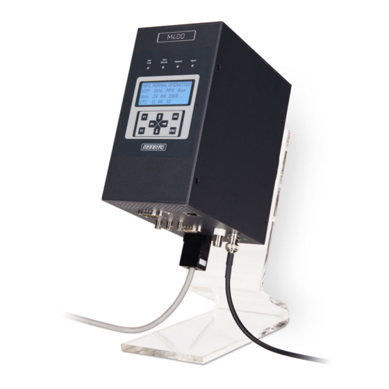
4 Technical Specifications LANTIME Chassis 4 Technical Specifications LANTIME Chassis Housing Housing for DIN mounting rail Housing material aluminium ——————————————————————————- Temperature range Operation 0 ... 50 C (32 ... 122 F) Storage -20 ... 70 C (-4 ... 158 F) ——————————————————————————- Relative humidity Operation... - Page 19 Housing dimensions Time Time Service Network Alarm GPS: NORMAL OPERATION NTP: Offs. PPS: 0µs Mon. 11.03.2020 UTC: 12:00:00 Date: 1st March 2021 LANTIME...
- Page 20 4 Technical Specifications LANTIME Chassis External ground connection on the housing Vor Öffnen des Gerätes alle Stecker ziehen! Before opening disconnect all mains! Avant d´ ´ ouvrir I´ ´ appareil débranchez tous les câbles d´ ´ alimentation This connector must be wired to an equipotential bonding bar (earthing bar). The connection is located below the rail mount bracket at the backside of the device.
-
Page 21: Lantime M400 Control Panel
5 LANTIME M400 Control Panel The main menu is displayed after switching on the device and having completed the initialization phase. In the main menu the most important status informa- tion are displayed. In the top line of the display the operating mode of the reference clock / reference time is shown. - Page 22 5 LANTIME M400 Control Panel By using the 4 arrows and the buttons "ESC", "F1" and "F2" of the keypad, you can navigate through each menu on the display. You can always return to the main menu by pressing the "ESC" button several times. "Ref.
-
Page 23: Lantime M400 Connectors
6 LANTIME M400 Connectors Date: 1st March 2021 LANTIME... -
Page 24: Power Connector
6 LANTIME M400 Connectors 6.1 Power Connector Connector Type: 5-pol. DFK Pin Assignment: 1: N/- 2: not connected 3: PE (Protective Earth) 4: not connected 5: L/+ 100-240 V 100-240 V , 50-60 Hz Input Parameter —————————————————————————— Nominal voltage range: 100-240 V 100-240 V Max. -
Page 25: Fuse
6.2 Fuse The fuse protects against overload or short circuits and thus prevents damage to the installed power supply. The fuse is accessible from the front panel and can be replaced. Technical Specification ———————————————————— Rated Voltage: 250 V Shutter delay: slow blow Rated Current: 1.6 A... -
Page 26: Rs-232 Comx Timestring
6 LANTIME M400 Connectors 6.4 RS-232 COMx Timestring Data transfer: serial Baudrate/framing: 19200 / 8N1 (default) Time-string: Meinberg Standard (default) Assignment: Pin 2: RxD (receive) Pin 3: TxD (transmit) Pin 5: GND (ground) COM x Connection type: D-SUB 9pin male connector... -
Page 27: 10/100Base-T Network Port (Ieee 803.2)
6.7 10/100BASE-T Network Port (IEEE 803.2) Signal: 100BASE-T Data transmission rate: 10/100 Mbit/s Connection type: 8P8C (RJ45) Cable: Copper twisted pair, e.g. CAT 5.0 Duplex Modes: Half/Full/Autonegotiaton Date: 1st March 2021 LANTIME... -
Page 28: Antenna Input - Gps Reference Clock
6 LANTIME M400 Connectors 6.8 Antenna Input - GPS Reference Clock Antenna input GPS180: Antenna circuit electrically isolated N-Norm N-type Dielectric strength: 1000 V Receiver type: 12 channel GPS C/A-Code receiver Antenna Antenna GNSS | IF | 15 V GNSS | IF | 15 V Mixed frequency Reference clock to antenna (GPS-converter):... -
Page 29: Pulse Per Second Output
6.9 Pulse Per Second Output Output signal: PPS (pulse per second) Signal level: TTL 2.5 V into 50 Ohm Pulse length: 200 ms Connection type: BNC, female PPS Out Cable: shielded coax line 6.10 10 MHz Frequency Output Output signal: 10 MHz frequency Signal level: TTL, 2.5 V into 50 Ohm... -
Page 30: Error Relay
6 LANTIME M400 Connectors 6.11 Error Relay On the back panel of the device you can find a DFK connector labeled "Error". This relay output is con- nected to the TTL TIME_SYNC output of the refer- Error ence clock (GPS, PZF, TCR, ...). If the internal refer- ence clock has been synchronized by its source (GPS, DCF77 or IRIG) the relay will switch to mode "NO". -
Page 31: Installation Gps Antenna
7 Installation GPS Antenna WARNING! Antenna mounting without effective anti-fall protection Danger to life due to fall! - Pay attention to effective working safety when installing antennas! - Never work without an effective anti-fall equipment! WARNING! Working on the antenna system during thunderstorms Danger to life due to electrical shock! - Do not carry out any work on the antenna system or the antenna cable if there is a risk of a lightning strike. - Page 32 7 Installation GPS Antenna Antenna Mounting Mount the antenna at a distance of 50 cm from other Free view to the sky! antennas to a vertical pole up to 60 mm outer diameter or on a wall with the mounting kit included in the scope of delivery.
- Page 33 Earth cable to PE rail To ground the antenna cable, connect the surge Cable circa 1,5 mm Ø protection with a grounding cable to a equipotential attached to the surge protection bonding rail (see figure). After installation, connect the other end of the as short as possible antenna cable to the socket of the surge protection.
- Page 34 7 Installation GPS Antenna Antenna splitter option Several receivers can be connected to one antenna via the antenna splitter. Make sure, that the total length of a route going from the antenna via the splitter to the receiver, does not exceed the maximum cable length. The splitter may be installed at any position between the surge protector and the receiver.
-
Page 35: Technical Appendix - Gps Antenna + Accessories
8 Technical Appendix - GPS Antenna + Accessories Physical Dimensions: Date: 1st March 2021 LANTIME... - Page 36 8 Technical Appendix - GPS Antenna + Accessories Specifications: Power supply: 15 V, 100 mA (provided via antenna cable) Receive frequency: 1575.42 MHz Bandwidth: 9 MHz Frequencies: Mixed frequency 10 MHz IF frequency: 35.4 MHz Connector: N-Norm female connector Form factor: ABS plastic case for outdoor installation Protection class: IP66...
-
Page 37: Antenna Cable
8.1 Antenna Cable: Cable type Cable (mm/in) Attenuation at 100 MHz max. Cable lenght (m/ft) used for receiver type (db)/100m/328ft RG58/CU 5/0.2 300/984 GPS/GNS-UC/PZF RG213 10,3/0.41 700/2297 GPS/GNS-UC H155 5,4/0,21 70/230 GNM/GNS H2010 Ultraflex 7,3/0,29 150/492 GNM/GNS Further values can be found in the data sheet of the cable used. 8.2 Antenna Short-Circuit (Only for assembly groups with front display) In case of an antenna line short-circuit the following message appears in the display:... -
Page 38: Technical Specifications - Mbg S-Pro Surge Protection
8 Technical Appendix - GPS Antenna + Accessories 8.3 Technical Specifications - MBG S-PRO surge protection Attachment plug with replaceable gas discharge tube for coaxial signal interfaces. Connection: N connector female/female. The MBG S-PRO set includes a surge voltage protector (Phoenix CN-UB-280DC-BB), a pre- assembled coax cable and a mounting bracket. - Page 39 Max. discharge current (8/20) s maximum (Core-Shield) 20 kA Nominal pulse current (10/1000) s (Core-Shield) 100 A Impulse discharge current (10/350) s, peak value I 2,5 kA Output voltage limitation at 1 kV/ s (Core-Earth) spike 900 V at 1 kV/ s (Core-Earth) spike 900 V Response time tA (Core-Earth)
-
Page 40: Mbg S-Pro - Physical Dimensions
8 Technical Appendix - GPS Antenna + Accessories 8.3.1 MBG S-PRO - Physical Dimensions 15,8 8.3.2 Installation and Grounding LANTIME Date: 1st March 2021... -
Page 41: Rohs And Weee
Any transportation expenses for return- ing this product (at its end of life) have to be incurred by the end user, whereas Meinberg will bear the costs for the waste disposal itself. Date: 1st March 2021... -
Page 42: Declaration Of Conformity
10 Declaration of Conformity Declaration of Conformity Doc ID: LANTIME M400/GPS-2021-03-01 Hersteller Meinberg Funkuhren GmbH & Co. KG Manufacturer Lange Wand 9, D-31812 Bad Pyrmont erklärt in alleiniger Verantwortung, dass das Produkt, declares under its sole responsibility, that the product...
Need help?
Do you have a question about the LANTIME M400/GPS and is the answer not in the manual?
Questions and answers