Table of Contents
Advertisement
Quick Links
Advertisement
Table of Contents

Related Manuals for Rohde & Schwarz R&S RT-ZC05B


Summary of Contents for Rohde & Schwarz R&S RT-ZC05B
- Page 1 ® R&S RT-ZC05B Current Probe User Manual (>9àÆ2) 1409825602 Version 02...
- Page 2 This manual describes the following Rohde & Schwarz product: ● R&S ® RT-ZC05B, Current Probe (1409.8204.02) © 2020 Rohde & Schwarz GmbH & Co. KG Mühldorfstr. 15, 81671 München, Germany Phone: +49 89 41 29 - 0 Email: info@rohde-schwarz.com Internet: www.rohde-schwarz.com Subject to change –...
-
Page 3: Table Of Contents
® Contents R&S RT-ZC05B Contents 1 Notes on Safety..............5 2 Product Description.............. 9 2.1 Product Overview................. 9 2.2 Key Features..................9 2.3 Inspecting the Contents............... 9 2.4 Description of the Probe..............10 2.4.1 Sensor....................11 2.4.2 Probe Box..................... 12 3 Putting into Operation............13 3.1 Connecting the Probe to the Oscilloscope........ - Page 4 ® Contents R&S RT-ZC05B User Manual 1409.8256.02 ─ 02...
-
Page 5: Notes On Safety
® Notes on Safety R&S RT-ZC05B Notes on Safety Thank you for purchasing the R&S RT-ZC05B current probe. To obtain maximum performance from the device, please read this manual first, and keep it handy for future reference. Risk of physical injury This device is designed to comply with IEC 61010 Safety Standards, and has been thoroughly tested for safety before shipment. - Page 6 ® Notes on Safety R&S RT-ZC05B Risk of fatal injury ● To avoid electric shock and short circuits, never attach the clamp to bare, unisolated conductors. Make sure to measure at a location on an insulated wire where the insu- lation is sufficient for the circuit voltage.
- Page 7 ® Notes on Safety R&S RT-ZC05B Risk of instrument damage ● To avoid damage to the device, protect it from vibration or shock during transport and handling, and be especially careful to avoid dropping. ● Do not store or use the device where it could be exposed to direct sun- light, high temperature, humidity, or condensation.
- Page 8 ® Notes on Safety R&S RT-ZC05B Strong electromagnetic fields Correct measurement may be impossible in the presence of strong mag- netic fields, such as near transformers and high-current conductors, or in the presence of strong electromagnetic fields such as near radio transmitters. User Manual 1409.8256.02 ─...
-
Page 9: Product Description
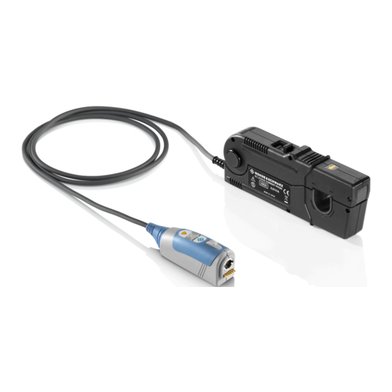
® Product Description R&S RT-ZC05B Inspecting the Contents Product Description Product Overview The R&S RT-ZC05B is an AC/DC current probe. It allows the user to make cur- rent measurements from DC to 2 MHz. By clamping on the conductor to be mea- sured, the current waveform is captured easily without interrupting the electric cir- cuit. -
Page 10: Description Of The Probe
® Product Description R&S RT-ZC05B Description of the Probe If the packaging material shows any signs of stress, notify the carrier and your Rohde & Schwarz service center. Keep the package and cushioning material for inspection. ● Inspect the probe. If there is any damage or defect, or if the R&S RT-ZC05B current probe does not operate properly, notify your Rohde &... -
Page 11: Sensor
® Product Description R&S RT-ZC05B Description of the Probe 1 = Sensor 2 = Probe box 3 = Sensor cable 4 = Sensor head (clamp) 5 = Slider 6 = Lever 7 = Current direction indication 8 = Lock/Unlock indication 2.4.1 Sensor The sensor consists of the following parts:... -
Page 12: Probe Box
® Product Description R&S RT-ZC05B Description of the Probe 2.4.2 Probe Box The probe box connects the probe and the oscilloscope via the Rohde & Schwarz probe interface. The Rohde & Schwarz probe interface contains a male precision 7 mm (276 mil) BNC connector and six pogo pin connectors. This interface pro- vides the required supply voltage and is also used to transmit analog signals and digital data simultaneously. -
Page 13: Putting Into Operation
® Putting into Operation R&S RT-ZC05B Connecting the Probe to the Oscilloscope Putting into Operation Connecting the Probe to the Oscilloscope The output of the probe is terminated internally. Use an Rohde & Schwarz oscilloscope with high impedance inputs. Accurate measurement is not pos- sible, with an impedance of 50 Ω. -
Page 14: Identification Of The Probe
® Putting into Operation R&S RT-ZC05B Identification of the Probe Figure 3-1: Connecting the probe to the Rohde & Schwarz oscilloscope ► To disconnect the probe: a) Press and hold the release button (3). b) Pull the probe box away from the oscilloscope. Identification of the Probe When the probe is connected to the oscilloscope, the oscilloscope recognizes the probe and reads out the probe-specific parameters. -
Page 15: Setting Up And Demagnetizing
® Putting into Operation R&S RT-ZC05B Setting Up and Demagnetizing Setting Up and Demagnetizing Before starting measurements, demagnetizing the core and a zero adjustment of the probe are required. Risk of circuit damage Do not demagnetize while the R&S RT-ZC05B is clamping a conductor to be measured. -
Page 16: Connecting The Probe To The Dut
® Putting into Operation R&S RT-ZC05B Connecting the Probe to the DUT This demagnetizes the core if it has been magnetized by switching the power on and off, or by an excessive input. Always carry out demagnetizing before measurement. The demagnetizing process takes about 3 seconds. During demagnetizing, a demagnetizing waveform is present at the output. - Page 17 ® Putting into Operation R&S RT-ZC05B Connecting the Probe to the DUT 5. Press the slider on the sensor head until the UNLOCK indication disappears. Hold it until LOCK appears. Check, if the opening lever is firmly locked and the clamp is securely closed. If the sensor head is not properly closed, accurate measurement is not possible.
- Page 18 ® Putting into Operation R&S RT-ZC05B Connecting the Probe to the DUT Risk of instrument damage due to continuous input current ● At high ambient temperatures, the built-in safety circuit may activate at current input levels below the rated continuous maximum current. ●...
- Page 19 ® Putting into Operation R&S RT-ZC05B Connecting the Probe to the DUT ● Immediately after powering on, this device may be subject to an appre- ciable offset drift due to the effect of self-heating. To counteract this, allow the device to warm up for about 30 minutes before carrying out measurements.
-
Page 20: Maintenance And Service
® Maintenance and Service R&S RT-ZC05B Contacting Customer Support Maintenance and Service If service or calibration is needed, contact your Rohde & Schwarz service center. Return a defective product to the Rohde & Schwarz service center for diagnosis and exchange. Cleaning 1. -
Page 21: Returning For Servicing
® Maintenance and Service R&S RT-ZC05B Calibration Interval Figure 4-1: QR code to the Rohde & Schwarz support page Returning for Servicing Use the original packaging to return your R&S RT-ZC05B to your Rohde & Schwarz service center. A list of all service centers is available on: www.services.rohde-schwarz.com If you cannot use the original packaging, consider the following: 1. -
Page 22: Discarding The Product
® Maintenance and Service R&S RT-ZC05B Discarding the Product Discarding the Product Handle and dispose the product in accordance with local regulations. User Manual 1409.8256.02 ─ 02...
Need help?
Do you have a question about the R&S RT-ZC05B and is the answer not in the manual?
Questions and answers