
Related Manuals for Rohde & Schwarz R&S NRQ6


Summary of Contents for Rohde & Schwarz R&S NRQ6
- Page 1 www.allice.de Allice Messtechnik GmbH ® R&S NRQ6 Frequency Selective Power Sensor Getting Started (;ÜU52) 1178370502 https://allice.de/rohde-schwarz/value-instruments/...
- Page 2 www.allice.de Allice Messtechnik GmbH This document describes the following power sensor: ● R&S ® NRQ6 (1421.3509.02) © 2020 Rohde & Schwarz GmbH & Co. KG Mühldorfstr. 15, 81671 München, Germany Phone: +49 89 41 29 - 0 Email: info@rohde-schwarz.com Internet: www.rohde-schwarz.com Subject to change –...
-
Page 3: Table Of Contents
www.allice.de Allice Messtechnik GmbH ® Contents R&S NRQ6 Contents 1 Safety Information..............7 2 Documentation Overview............9 2.1 Getting Started Manual.................9 2.2 User Manual...................9 2.3 CD-ROM....................9 2.4 Application Sheets................10 2.5 Tutorials....................10 2.6 Instrument Security Procedures............10 2.7 Basic Safety Instructions..............10 2.8 Data Sheets and Brochures............... - Page 4 www.allice.de Allice Messtechnik GmbH ® Contents R&S NRQ6 4.6.1.3 Setup with a PoE+ Injector..............22 4.6.1.4 Establishing a Connection..............22 4.6.1.5 Using Hostnames..................23 4.6.1.6 Assigning the IP Address..............24 4.6.2 Computer Using a USB Connection............. 25 4.6.2.1 Simple USB Connection............... 25 4.6.2.2 R&S NRP‑Z5 Sensor Hub Setup............26 4.6.3 R&S NRX Base Unit................
- Page 5 www.allice.de Allice Messtechnik GmbH ® Contents R&S NRQ6 6.2.3 Toolbar in Charts...................45 6.2.4 Setting Parameters................45 6.3 R&S NRX....................47 6.4 Remote Control................... 48 7 Remote Control Interfaces and Protocols......51 7.1 USB Interface..................51 7.2 Ethernet Interface................53 7.2.1 VISA Resource Strings................. 53 7.2.2 VXI-11 Protocol..................
- Page 6 www.allice.de Allice Messtechnik GmbH ® Contents R&S NRQ6 Getting Started 1178.3705.02 ─ 07 https://allice.de/rohde-schwarz/value-instruments/...
-
Page 7: Safety Information
www.allice.de Allice Messtechnik GmbH ® Safety Information R&S NRQ6 Safety Information The product documentation helps you use the R&S NRQ6 safely and efficiently. Follow the instructions provided here and in the printed "Basic Safety Instruc- tions". Keep the product documentation nearby and offer it to other users. Intended use The R&S NRQ6 is intended for the development, production and verification of electronic components and devices in industrial, administrative, and laboratory... - Page 8 www.allice.de Allice Messtechnik GmbH ® Safety Information R&S NRQ6 Getting Started 1178.3705.02 ─ 07 https://allice.de/rohde-schwarz/value-instruments/...
-
Page 9: Documentation Overview
www.allice.de Allice Messtechnik GmbH ® Documentation Overview R&S NRQ6 CD-ROM Documentation Overview This section provides an overview of the R&S NRQ6 user documentation. Unless specified otherwise, you find the documents on the R&S NRQ6 product page at: www.rohde-schwarz.com/manual/NRQ6 Getting Started Manual Introduces the R&S NRQ6 and describes how to set up and start working with the product. -
Page 10: Application Sheets
www.allice.de Allice Messtechnik GmbH ® Documentation Overview R&S NRQ6 Data Sheets and Brochures ● Links to useful sites on the Rohde & Schwarz website Application Sheets Deal with special tasks and their practical solution. Tutorials Tutorials offer guided examples and demonstrations on operating the R&S NRQ6. They are provided on the product page of the internet. -
Page 11: Release Notes And Open Source Acknowledgment (Osa)
www.allice.de Allice Messtechnik GmbH ® Documentation Overview R&S NRQ6 Application Notes, Application Cards, White Papers, etc. Release Notes and Open Source Acknowledg- ment (OSA) The release notes list new features, improvements and known issues of the cur- rent firmware version, and describe the firmware installation. The "Open Source Acknowledgment"... - Page 12 www.allice.de Allice Messtechnik GmbH ® Documentation Overview R&S NRQ6 Application Notes, Application Cards, White Papers, etc. Getting Started 1178.3705.02 ─ 07 https://allice.de/rohde-schwarz/value-instruments/...
-
Page 13: Key Features
www.allice.de Allice Messtechnik GmbH ® Key Features R&S NRQ6 Key Features The R&S NRQ6 frequency selective power sensor sets standards in RF perfor- mance and usability. Outstanding key features are: ● Combines the advantages of a measurement receiver (dynamic range, linear- ity &... - Page 14 www.allice.de Allice Messtechnik GmbH ® Key Features R&S NRQ6 Getting Started 1178.3705.02 ─ 07 https://allice.de/rohde-schwarz/value-instruments/...
-
Page 15: Preparing For Use
www.allice.de Allice Messtechnik GmbH ® Preparing for Use R&S NRQ6 Operating Conditions Preparing for Use ● Unpacking and Checking the Power Sensor...........15 ● Operating Conditions..................15 ● Considerations for Test Setup................. 16 ● Connecting to a DUT..................17 ● Connecting to a Power Supply................18 ●... -
Page 16: Considerations For Test Setup
www.allice.de Allice Messtechnik GmbH ® Preparing for Use R&S NRQ6 Considerations for Test Setup on the power sensor, observe the information on appropriate operating conditions provided in the basic safety instructions and the data sheet of the R&S NRQ6. In particular, ensure the following: ●... -
Page 17: Connecting To A Dut
www.allice.de Allice Messtechnik GmbH ® Preparing for Use R&S NRQ6 Connecting to a DUT Connecting to a DUT The R&S NRQ6 has fan openings at both sides of the casing, as shown in Fig- 5-1. When connecting the R&S NRQ6 to a DUT and setting up the measure- ment assembly, be careful to allow sufficient airflow. -
Page 18: Connecting To A Power Supply
www.allice.de Allice Messtechnik GmbH ® Preparing for Use R&S NRQ6 Connecting to a Power Supply To disconnect from the DUT 1. NOTICE! Risk of damaging the center pin of the RF connector. Only rotate the hex nut of the RF connector. Never rotate the R&S NRQ6 itself. Carefully loosen the union nut at the front of the RF connector of the R&S NRQ6. -
Page 19: Connecting To A Controlling Host
www.allice.de Allice Messtechnik GmbH ® Preparing for Use R&S NRQ6 Connecting to a Controlling Host Chapter 4.6.1.3, "Setup with a PoE+ Injector", on page 22. Connecting to a Controlling Host For operating the R&S NRQ6, you can choose from various possibilities. For details, see Chapter 6, "Operating Concepts",... -
Page 20: Setup With A Poe+ Ethernet Switch
www.allice.de Allice Messtechnik GmbH ® Preparing for Use R&S NRQ6 Connecting to a Controlling Host 4.6.1.1 Setup with a PoE+ Ethernet Switch LAN PoE+ NRQ6 Frequency Selective Power Sensor Host Interface LO I/0 Sample Clock I/O (Default: 120 MHz) Network (PoE+) Figure 4-1: Setup with a PoE+ Ethernet switch = Signal source (DUT) = R&S NRQ6... -
Page 21: Setup With A Poe+ Injector And A Non-Poe+ Ethernet Switch
www.allice.de Allice Messtechnik GmbH ® Preparing for Use R&S NRQ6 Connecting to a Controlling Host 4.6.1.2 Setup with a PoE+ Injector and a Non-PoE+ Ethernet Switch LAN PoE+ NRQ6 Frequency Selective Power Sensor Host Interface LO I/0 Sample Clock I/O (Default: 120 MHz) Non-PoE+ PoE+ Injector Ethernet Switch... -
Page 22: Setup With A Poe+ Injector
www.allice.de Allice Messtechnik GmbH ® Preparing for Use R&S NRQ6 Connecting to a Controlling Host 4.6.1.3 Setup with a PoE+ Injector LAN PoE+ NRQ6 Frequency Selective Power Sensor Host Interface LO I/0 Sample Clock I/O (Default: 120 MHz) PoE+ Injector Figure 4-3: Setup with a PoE+ injector = Signal source (DUT) = R&S NRQ6... -
Page 23: Using Hostnames
www.allice.de Allice Messtechnik GmbH ® Preparing for Use R&S NRQ6 Connecting to a Controlling Host ● Chapter 4.6.1.6, "Assigning the IP Address", on page 24 To set up a network Ethernet connection 1. Connect the R&S NRQ6 to the network or to a single computer. By default, the R&S NRQ6 is configured to use dynamic TCP/IP configuration (DHCP) and to obtain the address information automatically. -
Page 24: Assigning The Ip Address
www.allice.de Allice Messtechnik GmbH ® Preparing for Use R&S NRQ6 Connecting to a Controlling Host Example: Serial number of the R&S NRQ6: 101441 Default hostname: nrq6-101441 Hostname in zero configuration networks, including peer-to-peer networks The R&S NRQ6 supports zero configuration networking, used in networks without DHCP server, such as peer-to-peer networks. -
Page 25: Computer Using A Usb Connection
www.allice.de Allice Messtechnik GmbH ® Preparing for Use R&S NRQ6 Connecting to a Controlling Host Identify the R&S NRQ6 using hostnames In networks using a DHCP server, it is recommended that you address the R&S NRQ6 by its unique hostname, see Chapter 4.6.1.5, "Using Host- names", on page 23. -
Page 26: R&S Nrp-Z5 Sensor Hub Setup
www.allice.de Allice Messtechnik GmbH ® Preparing for Use R&S NRQ6 Connecting to a Controlling Host 5 = USB connector 6 = Computer with installed VISA driver or R&S NRP Toolkit 7 = PoE+ injector 8 = AC supply 1. Connect the R&S NRQ6 to the signal source (DUT), see Chapter 4.4, "Con- necting to a DUT",... - Page 27 www.allice.de Allice Messtechnik GmbH ® Preparing for Use R&S NRQ6 Connecting to a Controlling Host TTL /CMOS TTL /CMOS PoE+ Injector ‑ Z5 sensor hub Figure 4-5: Configuration with an R&S NRP = AC power supply = Computer with USB host interface = Trigger source (optional) = Triggered device (optional) = Power cable...
-
Page 28: R&S Nrx Base Unit
www.allice.de Allice Messtechnik GmbH ® Preparing for Use R&S NRQ6 Connecting to a Controlling Host c) R&S NRP‑Z5 using a R&S NRP‑ZK8 cable. 2. Connect the R&S NRP‑Z5 to the computer using a USB cable. 3. Connect the delivered external power supply unit to the R&S NRP‑Z5 and to an AC supply connector. - Page 29 www.allice.de Allice Messtechnik GmbH ® Preparing for Use R&S NRQ6 Connecting to a Controlling Host Use an R&S NRP‑ZK8 cable. 1. 8-pin female connector of R&S NRP‑ZK8: a) Insert the screw-lock cable connector into the host interface of the R&S NRQ6. b) Tighten the union nut manually.
- Page 30 www.allice.de Allice Messtechnik GmbH ® Preparing for Use R&S NRQ6 Connecting to a Controlling Host Getting Started 1178.3705.02 ─ 07 https://allice.de/rohde-schwarz/value-instruments/...
-
Page 31: S Nrq6 Tour
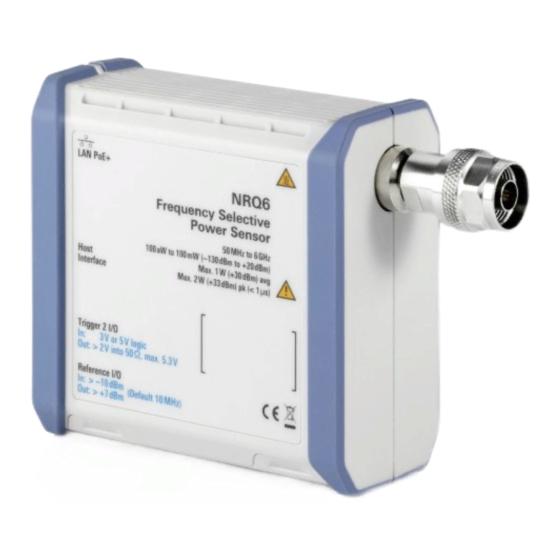
www.allice.de Allice Messtechnik GmbH ® R&S NRQ6 Tour R&S NRQ6 R&S NRQ6 Tour This chapter provides an overview of the available connectors and LEDs of the R&S NRQ6. Figure 5-1: R&S NRQ6 frequency selective power sensor = RF connector, see Chapter 5.1, "RF Connector", on page 32... -
Page 32: Rf Connector
www.allice.de Allice Messtechnik GmbH ® R&S NRQ6 Tour R&S NRQ6 Status Information RF Connector See (1) in Figure 5-1. The male N connector is used to connect the R&S NRQ6 to the device under test (DUT) or a signal generator, see Chapter 4.4, "Connecting to a DUT", on page 17. -
Page 33: Lan Poe+ Interface
www.allice.de Allice Messtechnik GmbH ® R&S NRQ6 Tour R&S NRQ6 LAN PoE+ Interface Color Illumination State Slow blinking Static error Fast blinking Critical static error Note: If this state occurs after a firmware update, the update was not successful. Further information: ●... - Page 34 www.allice.de Allice Messtechnik GmbH ® R&S NRQ6 Tour R&S NRQ6 LAN PoE+ Interface Figure 5-2: LAN [PoE+] interface 1 = Network status LED 2 = PoE+ status LED 3 = LAN reset button Network status LED See (1) in Figure 5-2.
-
Page 35: Host Interface
www.allice.de Allice Messtechnik GmbH ® R&S NRQ6 Tour R&S NRQ6 Reference I/O (REF) After a LAN reset, the Ethernet interface is set DHCP mode where automatic address allocation is attempted. Host Interface See (4) in Figure 5-1. The 8-pole male sensor connector (M12) is used to connect the R&S NRQ6 to a computer or an R&S NRX base unit. -
Page 36: Clock I/O (Clk)
www.allice.de Allice Messtechnik GmbH ® R&S NRQ6 Tour R&S NRQ6 Local Oscillator I/O (LO) (output). Also, you can supply an external reference signal and use it as refer- ence clock instead of the internal reference signal (input). For input and output specifications, read the label on the R&S NRQ6 casing and the data sheet. -
Page 37: Fan Openings
www.allice.de Allice Messtechnik GmbH ® R&S NRQ6 Tour R&S NRQ6 Fan Openings Fan Openings See (9, 10) in Figure 5-1. The R&S NRQ6 has fan openings on the top and on the bottom of the casing. When connecting the R&S NRQ6, be careful to allow sufficient airflow as speci- fied in Chapter 4.4, "Connecting to a DUT",... - Page 38 www.allice.de Allice Messtechnik GmbH ® R&S NRQ6 Tour R&S NRQ6 Fan Openings Getting Started 1178.3705.02 ─ 07 https://allice.de/rohde-schwarz/value-instruments/...
-
Page 39: Operating Concepts
www.allice.de Allice Messtechnik GmbH ® Operating Concepts R&S NRQ6 R&S NRP Toolkit Operating Concepts For operating the R&S NRQ6, you can choose from the following possibilities: ● Chapter 6.2, "Browser-Based User Interface", on page 41 ● Chapter 6.3, "R&S NRX", on page 47 ●... -
Page 40: System Requirements
www.allice.de Allice Messtechnik GmbH ® Operating Concepts R&S NRQ6 R&S NRP Toolkit 6.1.2 System Requirements Hardware requirements: ● Desktop computer or laptop, or an Intel-based Apple Mac ● LAN interface and equipment for setting up a LAN connection. Chapter 4.6.1, "Computer Using a LAN Connection", on page 19. -
Page 41: Performing A Firmware Update
www.allice.de Allice Messtechnik GmbH ® Operating Concepts R&S NRQ6 Browser-Based User Interface 3. Accept the license terms to continue with the installation. 4. Click "Next" and complete the installation process. 6.1.3.1 Performing a Firmware Update The Firmware Update for NRP Family program is part of the R&S NRP Toolkit for Windows. - Page 42 www.allice.de Allice Messtechnik GmbH ® Operating Concepts R&S NRQ6 Browser-Based User Interface You can use the web user interface with all devices and operating systems, including tablets and smart phones. ● Supported web browser: – Mozilla Firefox 56 or later –...
-
Page 43: Layout Of The Main Dialog
www.allice.de Allice Messtechnik GmbH ® Operating Concepts R&S NRQ6 Browser-Based User Interface 6.2.1 Layout of the Main Dialog The main dialog of the web user interface gives access to all available settings. Figure 6-1: Layout of the web user interface 1 = Sensor name or hostname 2 = Status information 3 = Sensor information... -
Page 44: Tooltips
www.allice.de Allice Messtechnik GmbH ® Operating Concepts R&S NRQ6 Browser-Based User Interface If the R&S NRQ6 is in remote mode, the status is displayed next to the status LED, see Figure 6-2. Sensor information (3) in Figure 6-1 Serial number of the R&S NRQ6 and installed firmware version Top pane (4) in Figure 6-1... -
Page 45: Toolbar In Charts
www.allice.de Allice Messtechnik GmbH ® Operating Concepts R&S NRQ6 Browser-Based User Interface 6.2.3 Toolbar in Charts If you move the mouse into a chart, a toolbar becomes visible in the upper right corner. Use the toolbar to analyze the chart in detail. Table 6-1: Icons for chart analysis Icon Description... - Page 46 www.allice.de Allice Messtechnik GmbH ® Operating Concepts R&S NRQ6 Browser-Based User Interface Table 6-2 for the available short forms of units. Table 6-2: Short forms of units Quantity Short Corresponding forms * unit Frequency Time μs * Both capital and small letters are accepted. ►...
-
Page 47: R&S Nrx
www.allice.de Allice Messtechnik GmbH ® Operating Concepts R&S NRQ6 R&S NRX To toggle between two possible values If only two values are possible, you can toggle between these values. Toggling works for the pairs "Off"/"On", "Auto"/"Manual", "Left"/"Right", etc. ► Click the value to change to the other value. R&S NRX In a measurement, the R&S NRX uses all sensor-dependent measurement func- tions and displays the results. -
Page 48: Remote Control
www.allice.de Allice Messtechnik GmbH ® Operating Concepts R&S NRQ6 Remote Control The measurement starts, and the result is displayed in dBm. 5. If necessary, perform further settings. For a detailed description of how to measure in this setup, refer to the user man- ual of the R&S NRX. - Page 49 www.allice.de Allice Messtechnik GmbH ® Operating Concepts R&S NRQ6 Remote Control The R&S NRQ6 changes into local mode. The lock of the web user interface is removed. Further information: ● See the user manual for details. ● Chapter 7, "Remote Control Interfaces and Protocols", on page 51 ●...
- Page 50 www.allice.de Allice Messtechnik GmbH ® Operating Concepts R&S NRQ6 Remote Control Getting Started 1178.3705.02 ─ 07 https://allice.de/rohde-schwarz/value-instruments/...
-
Page 51: Remote Control Interfaces And Protocols
www.allice.de Allice Messtechnik GmbH ® Remote Control Interfaces and Protocols R&S NRQ6 USB Interface Remote Control Interfaces and Proto- cols For remote control, communication between the R&S NRQ6 and the controlling host is established based on the following interfaces and protocols. Table 7-1: Supported interfaces and protocols Interface Protocol Library... - Page 52 www.allice.de Allice Messtechnik GmbH ® Remote Control Interfaces and Protocols R&S NRQ6 USB Interface Apart from the USBTMC driver, which comes with the installation of the R&S NRP Toolkit, you do not have to install a separate driver. Setup 1. Connect the host interface of the R&S NRQ6 and the USB interface of the computer, see Chapter 4.6.2, "Computer Using a USB Connection",...
-
Page 53: Ethernet Interface
www.allice.de Allice Messtechnik GmbH ® Remote Control Interfaces and Protocols R&S NRQ6 Ethernet Interface Ethernet Interface The Ethernet interface of the R&S NRQ6 allows you to integrate it in a local area network (LAN). Requirements ● TCP/IP network protocol The local area network must support the TCP/IP network protocol. The TCP/IP network protocol and the associated network services are precon- figured on the R&S NRQ6. - Page 54 www.allice.de Allice Messtechnik GmbH ® Remote Control Interfaces and Protocols R&S NRQ6 Ethernet Interface The IP address or hostname is used by the programs to identify and control the sensor. While the hostname is determined by settings in the sensor, the IP address is assigned by a DHCP server when the sensor requests one.
-
Page 55: Vxi-11 Protocol
www.allice.de Allice Messtechnik GmbH ® Remote Control Interfaces and Protocols R&S NRQ6 Ethernet Interface Example: A power sensor has the IP address 10.111.11.20; the valid resource string using VXI-11 protocol is: TCPIP::10.111.11.20::INSTR The DNS hostname is nrq6-100001; the valid resource string is: TCPIP::nrq6-100001::hislip0 (HiSLIP) TCPIP::nrq6-100001::inst0 (VXI-11) A raw socket connection can be established using:... -
Page 56: Socket Communication
www.allice.de Allice Messtechnik GmbH ® Remote Control Interfaces and Protocols R&S NRQ6 Ethernet Interface The HiSLIP data is sent to the device using the "fire and forget" method with immediate return. Opposed to VXI-11, where each operation is blocked until a VXI-11 device handshake returns. Thus, a successful return of a VISA operation such as viWrite() does not guarantee that the sensor has finished (or even started) executing the requested command. -
Page 57: Contacting Customer Support
www.allice.de Allice Messtechnik GmbH ® Contacting Customer Support R&S NRQ6 Contacting Customer Support Technical support – where and when you need it For quick, expert help with any Rohde & Schwarz product, contact our customer support center. A team of highly qualified engineers provides support and works with you to find a solution to your query on any aspect of the operation, program- ming or applications of Rohde &... - Page 58 www.allice.de Allice Messtechnik GmbH ® Contacting Customer Support R&S NRQ6 Getting Started 1178.3705.02 ─ 07 https://allice.de/rohde-schwarz/value-instruments/...
-
Page 59: Index
www.allice.de Allice Messtechnik GmbH ® Index R&S NRQ6 Index Disconnecting DUT ............ 18 Accessory list .......... 15 R&S NRX ..........29 Application cards ........11 USB host ..........26 Application notes ........11 Download Application sheets ........10 R&S NRP Toolkit .........39 Connecting ..........17 Brochures .......... - Page 60 www.allice.de Allice Messtechnik GmbH ® Index R&S NRQ6 LAN connection Hostname ........... 23 R&S NRP Toolkit ........39 IP address ...........24 Components for Windows-based sys- Non-PoE+ Ethernet switch ....21 tems ............ 40 PoE+ Ethernet switch ......20 Firmware update ......... 41 PoE+ injector ........
- Page 61 www.allice.de Allice Messtechnik GmbH ® Index R&S NRQ6 Toolbar Chart ........... 45 Tooltips ............ 44 Trigger connector ........35 Tutorials ........... 10 Unpacking ..........15 USB connection Simple ..........25 USB sensor hub ........26 USB interface Remote control ........51 USB resource string ........
Need help?
Do you have a question about the R&S NRQ6 and is the answer not in the manual?
Questions and answers