Table of Contents
Advertisement
Quick Links
Advertisement
Table of Contents

Related Manuals for Rohde & Schwarz RT-ZZ80


Summary of Contents for Rohde & Schwarz RT-ZZ80
- Page 1 ® R&S RT-ZZ80 Transmission Line Probe User Manual (>9Úç2) 1409768902 Version 03...
- Page 2 All other trademarks are the properties of their respective owners. ® 1409.7689.02 | Version 03 | R&S RT-ZZ80 Throughout this manual, products from Rohde & Schwarz are indicated without the ® symbol and without ® product type numbers, e.g. R&S RT-ZZ80 is indicated as R&S RT-ZZ80.
-
Page 3: Table Of Contents
® Contents R&S RT-ZZ80 Contents 1 Safety and regulatory information........5 1.1 Safety instructions................5 1.2 Labels on the product................7 1.3 Warning messages in the documentation.......... 8 2 Product description...............9 2.1 Key features and key characteristics..........9 2.2 Unpacking and checking..............10 2.3 Description of the probe..............11... - Page 4 ® Contents R&S RT-ZZ80 4.2.1 Transmission line probes..............28 4.2.2 Input impedance................... 29 4.3 Attenuation dependence on source impedance......31 5 Maintenance and service............ 33 5.1 Cleaning....................33 5.2 Contacting customer support............33 5.3 Returning for servicing..............34 5.4 Calibration interval................34 5.5 Storage and transport................
-
Page 5: Safety And Regulatory Information
Use the product only for its designated purpose. Observe the operating conditions and performance limits stated in the data sheet. The R&S RT-ZZ80 transmission line probe is designed for measurements on cir- cuits that are only indirectly connected to the mains or not connected at all. It is not rated for any measurement category. - Page 6 ® Safety and regulatory information R&S RT-ZZ80 Safety instructions Using the product requires specialists or specially trained personnel. These users also need sound knowledge of at least one of the languages in which the user interfaces and the product documentation are available.
-
Page 7: Labels On The Product
® Safety and regulatory information R&S RT-ZZ80 Labels on the product ● Never cause any short circuits when measuring sources with high output cur- rents. ● Use only probes and accessories that comply with the measurement category (CAT) of your measurement task. If the product is rated for any measurement category, the permitted category is indicated on the product and in the data sheet. -
Page 8: Warning Messages In The Documentation
® Safety and regulatory information R&S RT-ZZ80 Warning messages in the documentation Warning messages in the documentation A warning message points out a risk or danger that you need to be aware of. The signal word indicates the severity of the safety hazard and how likely it will occur if you do not follow the safety precautions. -
Page 9: Product Description
Transmission line probes are best suited for measurements of broadband single- ended signals in impedance-controlled environments, for example, 50 Ω lines. The R&S RT-ZZ80 has a wide dynamic range. High input levels up to 20 V (RMS) can be measured without distortion. The low inherent noise enables the measure- ment of small input signals. -
Page 10: Unpacking And Checking
4. Check the equipment for damage. If the delivery is incomplete or equipment is damaged, contact Rohde & Schwarz. Delivery notes The delivery contains the following items: ● R&S RT-ZZ80 transmission line probe ● Carrying case ● Accessory boxes ●... -
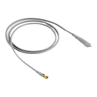
Page 11: Description Of The Probe
DUT. Different accessories for the signal and ground sockets allow the probe head to be connected to a wide range of DUTs. The signal socket of the R&S RT-ZZ80 has a special design to ensure optimal performance. The signal socket is not compatible to standard accessories based on 0.64 mm (25 mil) square pins or 0.8 mm (35 mil) round pins. -
Page 12: Sma Connector And Sma To Bnc Adapter
2.3.2 SMA connector and SMA to BNC adapter The R&S RT-ZZ80 has an SMA male connector for connection to the instrument. To connect the probe to a Rohde & Schwarz oscilloscope, you need the SMA to BNC adapter that is delivered with the probe. Screw the SMA connector on the SMA to BNC adapter as shown below. -
Page 13: Accessories And Items
® Product description R&S RT-ZZ80 Accessories and items Accessories and items The figure below shows all accessories that are available for the R&S RT-ZZ80 transmission line probe. SMA-BNC adapter marker band kit lead, 15 cm / 5.9 in lead 6 cm / 2.4 in... - Page 14 ® Product description R&S RT-ZZ80 Accessories and items Table 2-1: Accessories supplied Item Quantity Description Signal pin, solder in Signal pin Signal adapter, square pin Ground pin, solder in Ground pin, pogo Ground adapter, square pin R&S RT-ZA10 SMA (female) to BNC (male) adapter...
-
Page 15: Optional Accessories
The service kit includes all adapters and accessories to connect the probe to the required measuring instruments. R&S RT-ZZ80 Service Manual The service manual contains a detailed description of the performance test to verify the specifications, and other important service procedures. -
Page 16: Connecting The Probe
Connecting the probe to the oscilloscope Connecting the probe Handling the probe The R&S RT-ZZ80 can withstand a moderate amount of physical and electrical stress. To avoid damage, treat the probe with care: ● Handle the probe by the probe head. -
Page 17: Zero Adjustment
Zero adjustment The zero error can impair the measurement results, therefore, correct the zero error if necessary. The R&S RT-ZZ80 has no zero error. However, differences in DUT and oscilloscope ground levels can cause larger zero errors visible on the oscilloscope's screen. If the DUT is not floating but ground-referenced, an zero adjustment improves the measurement results. -
Page 18: Connecting The Probe To The Dut
® Connecting the probe R&S RT-ZZ80 Connecting the probe to the DUT 4. Adjust the zero position of the waveform using the appropriate function of the oscilloscope ("AutoZero", "Zero Adjust" or similar). The waveform is set to 0 V on the horizontal centerline of the oscilloscope. - Page 19 ® Connecting the probe R&S RT-ZZ80 Connecting the probe to the DUT Signal pin and ground pin, pogo Using the signal pin and ground pin, manual measurements can be performed without or with only minor limitation of the measurement bandwith. Best results are achieved if the dis- tance between signal and ground is small.
- Page 20 Connecting the probe to the DUT Signal pin, solder in, and ground pin, solder-in Using two solder-in pins for ground and signal, the R&S RT-ZZ80 is soldered directly into the circuit. The pins can be exchanged on the probe and can remain in the circuit.
- Page 21 ® Connecting the probe R&S RT-ZZ80 Connecting the probe to the DUT Signal adapter, square pin, and ground adapter, square pin Using two square-in pin adapters for ground and signal, the probe can be connected directly to a pin strip.
-
Page 22: Measurement Principles
R&S RT-ZZ80 Measurement principles The R&S RT-ZZ80 transmission line probe provides an electrical connection between the DUT and the oscilloscope. The probe transfers the voltage of the electrical signal tapped off the DUT to the oscilloscope, where it is displayed graphically. - Page 23 500 Ω 0.3 pF 50 Ω Circuit ground Probe ground Figure 4-1: Equivalent circuit model of the R&S RT-ZZ80 probe Table 4-1: Designations Abbreviation Description Voltage at the test point without probe connected Voltage at the test point with probe connected,...
-
Page 24: Signal Integrity Of The Transferred Signal
The following explanations refer to the probe itself, but can also be applied to the entire system. Figure 4-2: Amplitude frequency response of the R&S RT-ZZ80 The bandwidth: ● Specifies the maximum frequency at which a purely sinusoidal signal is still transferred at 70 % (–3 dB) of its amplitude. - Page 25 rise Figure 4-3 shows a typical step response of an R&S RT-ZZ80 transmission line probe. Figure 4-3: Step response of the R&S RT-ZZ80 In addition to bandwidth, a constant amplitude frequency response of the probe is decisive for high signal integrity. The...
-
Page 26: Performance With Different Connection Types
® Measurement principles R&S RT-ZZ80 Signal integrity of the transferred signal 4.1.2 Performance with different connection types Table 4-2 shows three types of connection between probe and DUT as well as the associated rise times, bandwidths, input impedances and overshoots. The... - Page 27 Measurement principles R&S RT-ZZ80 Signal integrity of the transferred signal Figure 4-4: Step response of the R&S RT-ZZ80 with a type 1 connection Figure 4-5: Step response of the R&S RT-ZZ80 with a type 2 connection User Manual 1409.7689.02 ─ 03...
-
Page 28: Signal Loading Of The Input Signal
R&S RT-ZZ80 Signal loading of the input signal Figure 4-6: Step response of the R&S RT-ZZ80 with a type 3 connection Signal loading of the input signal The previous section dealt with the transfer function and step response of the probe. -
Page 29: Input Impedance
Signal loading of the input signal Application range of transmission line probes Use the R&S RT-ZZ80 only for measurements of low-impedance sources, pref- erably in 50 Ω or 75 Ω impedance-controlled environments. The advantage of transmission line probes is the nearly constant input impedance over the frequency range, even at very high frequencies. - Page 30 R&S RT-ZZ80 Signal loading of the input signal Figure 4-7: Magnitude of the input impedance of the R&S RT-ZZ80 probe as a function of frequency Figure 4-8: Signal loading caused by the R&S RT-ZZ80 probe at an effective source impe- dance of 25 Ω...
-
Page 31: Attenuation Dependence On Source Impedance
) is therefore different from the signal that was present before the probe was connected (V In contrast to most other probes, the load of the R&S RT-ZZ80 is not negligible for DC and low-frequency signals. Therefore, the attenuation of the probe depends on the impedance of the signal source. - Page 32 To calculate the exact attenuation of the probe, use the following equation: Ω : output voltage : unloaded input voltage R´ input impedance of R&S RT-ZZ80 R´ : effective source impedance Example for a 50 Ω environment: Ω ...
-
Page 33: Maintenance And Service
® Maintenance and service R&S RT-ZZ80 Contacting customer support Maintenance and service Like all Rohde & Schwarz products, Rohde & Schwarz probes and adapters are of high quality and require only minimum service and repair. However, if service or calibration is needed, contact your Rohde & Schwarz service center. Return a defective product to the Rohde &... -
Page 34: Returning For Servicing
Calibration interval Figure 5-1: QR code to the Rohde & Schwarz support page Returning for servicing Use the original packaging to return your R&S RT-ZZ80 to your Rohde & Schwarzservice center. A list of all service centers is available on: www.services.rohde-schwarz.com If you cannot use the original packaging, consider the following: 1. -
Page 35: Storage And Transport
® Maintenance and service R&S RT-ZZ80 Spare parts Storage and transport Protect the product against dust. Ensure that the environmental conditions, e.g. temperature range and climatic load, meet the values specified in the data sheet. Store the product in a shock-resistant case, e.g. in the shipping case. - Page 36 ® Maintenance and service R&S RT-ZZ80 Spare parts Table 5-1: Accessory spare parts Pos. Item Description Material number Signal pin, solder in (50) 1417.0838.00 Signal pin 1175.7651.00 Signal adapter, square pin 1175.7668.00 Ground pin, solder in 1417.0538.00 Ground pin, pogo 1175.7716.00...
- Page 37 ® Maintenance and service R&S RT-ZZ80 Spare parts Pos. Item Description Material number Mini clip 1416.0105.00 Micro clip 1416.0111.00 R&S RT-ZA10 1316.0762.00 SMA (female) to BNC (male) adapter Marker band kit 1416.0205.00 R&S RT-ZK2 R&S RT-ZK2 service kit 1410.5305.02 Table 5-2: Parts for ESD prevention Pos.
Need help?
Do you have a question about the RT-ZZ80 and is the answer not in the manual?
Questions and answers