Table of Contents
Advertisement
Advertisement
Table of Contents

Subscribe to Our Youtube Channel
Related Manuals for Rohde & Schwarz R&S NRP-Z Series


Summary of Contents for Rohde & Schwarz R&S NRP-Z Series
- Page 1 ® R&S NRP-Zxx Power Sensors Getting Started (;ÚæF2) 1176.8822.02 ─ 03...
- Page 2 This manual gives an introduction to the Rohde & Schwarz NRP-Z sensors. The software contained in this product uses several valuable open source software packages. For information, see the "Open Source Acknowledgment" on the user documentation CD-ROM (included in delivery). Rohde &...
- Page 3 Basic Safety Instructions Always read through and comply with the following safety instructions! All plants and locations of the Rohde & Schwarz group of companies make every effort to keep the safety standards of our products up to date and to offer our customers the highest possible degree of safety. Our products and the auxiliary equipment they require are designed, built and tested in accordance with the safety standards that apply in each case.
- Page 4 Basic Safety Instructions Symbol Meaning Symbol Meaning Caution ! Hot surface Alternating current (AC) Protective conductor terminal Direct/alternating current (DC/AC) To identify any terminal which is intended for connection to an external conductor for protection against electric shock in case of a fault, or the terminal of a protective earth Earth (Ground) Class II Equipment...
- Page 5 Basic Safety Instructions Operating states and operating positions The product may be operated only under the operating conditions and in the positions specified by the manufacturer, without the product's ventilation being obstructed. If the manufacturer's specifications are not observed, this can result in electric shock, fire and/or serious personal injury or death. Applicable local or national safety regulations and rules for the prevention of accidents must be observed in all work performed.
- Page 6 Basic Safety Instructions 6. The product may be operated only from TN/TT supply networks fuse-protected with max. 16 A (higher fuse only after consulting with the Rohde & Schwarz group of companies). 7. Do not insert the plug into sockets that are dusty or dirty. Insert the plug firmly and all the way into the socket provided for this purpose.
- Page 7 Basic Safety Instructions 2. Before you move or transport the product, read and observe the section titled "Transport". 3. As with all industrially manufactured goods, the use of substances that induce an allergic reaction (allergens) such as nickel cannot be generally excluded. If you develop an allergic reaction (such as a skin rash, frequent sneezing, red eyes or respiratory difficulties) when using a Rohde &...
- Page 8 Basic Safety Instructions 2. Adjustments, replacement of parts, maintenance and repair may be performed only by electrical experts authorized by Rohde & Schwarz. Only original parts may be used for replacing parts relevant to safety (e.g. power switches, power transformers, fuses). A safety test must always be performed after parts relevant to safety have been replaced (visual inspection, protective conductor test, insulation resistance measurement, leakage current measurement, functional test).
- Page 9 Instrucciones de seguridad elementales 3. If you use the product in a vehicle, it is the sole responsibility of the driver to drive the vehicle safely and properly. The manufacturer assumes no responsibility for accidents or collisions. Never use the product in a moving vehicle if doing so could distract the driver of the vehicle.
- Page 10 Customer Support Technical support – where and when you need it For quick, expert help with any Rohde & Schwarz equipment, contact one of our Customer Support Centers. A team of highly qualified engineers provides telephone support and will work with you to find a solution to your query on any aspect of the operation, programming or applications of Rohde &...
-
Page 11: Table Of Contents
® Contents R&S NRP-Zxx Contents 1 Documentation Overview..............5 Getting Started Manual....................5 User Manuals.........................5 Tutorials......................... 5 Instrument Security Procedures..................5 Basic Safety Instructions..................... 5 Data Sheets and Brochures..................6 Release Notes and Open Source Acknowledgment (OSA)........6 Application Notes, Application Cards, White Papers, etc......... 6 2 For Your Safety.................. - Page 12 ® Contents R&S NRP-Zxx Compatible Instrument....................32 7 Remote Control..................34 Index......................35 Getting Started 1176.8822.02 ─ 03...
-
Page 13: Documentation Overview
® Documentation Overview R&S NRP-Zxx Basic Safety Instructions 1 Documentation Overview This section provides an overview of the R&S NRP‑Z power sensor user documenta- tion. Unless specified otherwise, you find the documents on the R&S NRP‑Z power sensor product page at: www.rohde-schwarz.com/product/nrpz 1.1 Getting Started Manual Introduces the R&S NRP‑Z power sensor and describes how to set up and start work-... -
Page 14: Data Sheets And Brochures
® Documentation Overview R&S NRP-Zxx Application Notes, Application Cards, White Papers, etc. 1.6 Data Sheets and Brochures The data sheet contains the technical specifications of the R&S NRP‑Z power sensor. It also lists the firmware applications and their order numbers, and optional accesso- ries. -
Page 15: For Your Safety
® For Your Safety R&S NRP-Zxx 2 For Your Safety The R&S NRP‑Z power sensor is designated for use in industrial, administrative, and laboratory environments. Use the R&S NRP‑Z power sensor only for its designated purpose. Observe the safety and usage instructions documented in the user manual, as well as operating conditions and performance limits stated in the data sheet. -
Page 16: Key Features
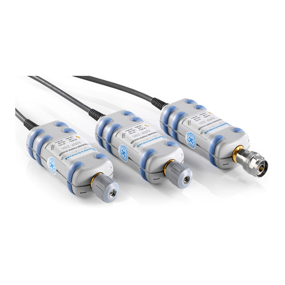
® Key Features R&S NRP-Zxx 3 Key Features Power measurements performed with the R&S NRP‑Z power sensors can be evalu- ated in various ways. This manual gives a short introduction to the solutions offered by Rohde & Schwarz for viewing your power measurement results. Also, you find a description of how to set up and measure power with your power sensor. - Page 17 ® Key Features R&S NRP-Zxx Overview of the R&S NRP‑Z power sensor types The R&S NRP‑Z power sensors are highly accurate standalone measuring instruments that offer all the functionality of conventional power meters, and more, within the small housing of a power sensor. With a high dynamic range, the different types of R&S NRP‑Z power sensors are suitable for nearly every measurement task: ●...
-
Page 18: Preparing For Use
® Preparing for Use R&S NRP-Zxx EMI Suppression 4 Preparing for Use This section describes the basic steps to be taken when setting up the R&S NRP‑Z power sensors for the first time. Risk of injury due to disregarding safety information Observe the information on appropriate operating conditions provided in the data sheet to prevent personal injury or damage to the power sensor. -
Page 19: Unpacking And Checking The Power Sensor
® Preparing for Use R&S NRP-Zxx Connectors of the R&S NRP‑Z Power Sensors 4.2 Unpacking and Checking the Power Sensor Check the equipment for completeness using the delivery note and the accessory lists for the various items. Check the power sensor for any damage. If there is damage, immediately contact the carrier who delivered the instrument. -
Page 20: Connecting The R&S Nrp-Z Power Sensors
® Preparing for Use R&S NRP-Zxx Connecting the R&S NRP‑Z Power Sensors Host connector See (1) in Figure 4-1. Lemo type host connector. You can plug it: ● Directly to a compatible Rohde & Schwarz instrument ● To a R&S NRP2 power meter base unit ●... - Page 21 ® Preparing for Use R&S NRP-Zxx Connecting the R&S NRP‑Z Power Sensors 3. To ensure a maximal measurement accuracy, tighten the RF connector using a tor- que wrench with the recommended nominal torque (see the operating manual of your power sensor). 4.4.2 Connecting the Host Connector of the R&S NRP‑Z Power Sensors To connect to an adapter You can use an R&S NRP‑Z3 or R&S NRP‑Z4 adapter.
-
Page 22: Disconnecting The R&S Nrp-Z Power Sensors
® Preparing for Use R&S NRP-Zxx Disconnecting the R&S NRP‑Z Power Sensors 4.5 Disconnecting the R&S NRP‑Z Power Sensors Additional requirements must be fulfilled when disconnecting the R&S NRP-Z27/-Z28/- Z37/-Z98 sensors. Refer to the operating manual of the corresponding sensor for a description on how to disconnect it. -
Page 23: Powering The R&S Nrp-Z Power Sensors
® Preparing for Use R&S NRP-Zxx Powering the R&S NRP‑Z Power Sensors Figure 4-3: Disconnecting from a SENSOR connector 1 = Ring of the built-in plug 2 = Cable sleeve 4.6 Powering the R&S NRP‑Z Power Sensors The R&S NRP‑Z power sensors can be powered in two ways: ●... -
Page 24: Connecting To A Pc
® Connecting to a PC R&S NRP-Zxx Using a Passive USB Adapter 5 Connecting to a PC There are different possibilities for connecting a power sensor to a PC, which can differ depending on the type of power sensor and available accessories. The following chapter gives an overview of the possible setups and what equipment is needed for each of them. -
Page 25: Using An Active Usb Adapter
® Connecting to a PC R&S NRP-Zxx Using an Active USB Adapter a) Connect the R&S NRP‑Z4 passive USB adapter to the power sensor. b) Connect the power sensor passive USB adapter to the computer. c) Connect the power sensor to the signal source. 2. -
Page 26: Using An R&S Nrp-Z5 Sensor Hub
® Connecting to a PC R&S NRP-Zxx Using an R&S NRP‑Z5 Sensor Hub Incorrectly connecting/disconnecting the R&S NRP‑Z power sensors may damage the power sensors or lead to erroneous results. Ensure that you connect/disconnect your power sensors as described in Chapter 4.4, "Connecting the R&S NRP‑Z Power Sensors",... - Page 27 ® Connecting to a PC R&S NRP-Zxx Using an R&S NRP‑Z5 Sensor Hub Setup ‑ Z5 sensor hub Figure 5-3: Setup with an R&S NRP = R&S NRP‑Z5 sensor hub = External power supply unit (supplied) = Power cable (supplied) = AC power supply = USB cable (supplied) = PC with USB host interface...
- Page 28 ® Connecting to a PC R&S NRP-Zxx Using an R&S NRP‑Z5 Sensor Hub Incorrectly connecting/disconnecting the R&S NRP‑Z power sensors may damage the power sensors or lead to erroneous results. Ensure that you connect/disconnect your power sensors as described in Chapter 4.4, "Connecting the R&S NRP‑Z Power Sensors",...
-
Page 29: Operating Concepts
® Operating Concepts R&S NRP-Zxx R&S NRP Toolkit 6 Operating Concepts For operating the power sensor, you can choose from various possibilities. Alternative to the methods of access described in this chapter, you can use remote control. For details, see: ●... - Page 30 ® Operating Concepts R&S NRP-Zxx R&S NRP Toolkit ● Microsoft Windows 10 32/64-bit ● Microsoft Windows XP 32-bit is available on request only. R&S NRP Toolkit versions for Linux distributions and MacOSX are also available on request. To obtain an R&S NRP Toolkit for an operating system other than Microsoft Windows, contact the Rohde &...
- Page 31 ® Operating Concepts R&S NRP-Zxx R&S NRP Toolkit 3. Click "Next" and complete the installation process. 6.1.3 Installing the R&S NRP Toolkit on a Linux-Based System The R&S NRP Toolkit for a certain Linux distribution comes as a series of Debian (*.deb) or RPM (*.rpm) files.
- Page 32 ® Operating Concepts R&S NRP-Zxx R&S NRP Toolkit The R&S NRP Toolkit installer opens. The welcome message gives an overview of the packages that are part of the installer and indicates their default installation location. 3. Accept the license terms to continue with the installation. 4.
- Page 33 ® Operating Concepts R&S NRP-Zxx R&S NRP Toolkit a) R&S NRP-Z Driver Framework (obligatory). b) Enable the "Power Viewer Plus application" (optional). c) Enable "Application Development" (optional). You can use these examples as starting points for your own implementations. 5. Click "Continue" and complete the installation process. After a successful installation, you can start the applications provided with the R&S NRP Toolkit from the Rohde-Schwarz folder that was created in the Mac OS X application directory.
-
Page 34: R&S Nrpv
® Operating Concepts R&S NRP-Zxx R&S NRPV 6.1.5 Performing a Firmware Update Use the firmware update program (PureFW) to load new firmware for the power sen- sors. It is part of the R&S NRP Toolkit that is supplied on a CD-ROM together with the power sensors. - Page 35 ® Operating Concepts R&S NRP-Zxx R&S NRPV Starting a measurement 1. Connect the power sensor to the PC as shown in Figure 6-1. 2. On the PC, start the R&S NRPV software. 3. Connect the power sensor to the PC. For a detailed description, see Chapter 5, "Connecting to a PC",...
-
Page 36: R&S Power Viewer Plus
® Operating Concepts R&S NRP-Zxx Android Device For a detailed description of how to measure in this setup, refer to the operating man- ual of the R&S NRPV. 6.3 R&S Power Viewer Plus The R&S Power Viewer Plus is software that simplifies many measurement tasks. It is provided on your documentation CD-ROM and on the Rohde &... - Page 37 ® Operating Concepts R&S NRP-Zxx Android Device – Compatible driver for the USB-OTG hardware. Make sure that this driver is already integrated in the device's kernel. Usually it cannot be installed sepa- rately. ● Installed R&S Power Viewer Mobile app ●...
-
Page 38: R&S Nrp2
® Operating Concepts R&S NRP-Zxx R&S NRP2 4. To skip this authorization for future uses, enable "Use by default for this USB device" before clicking OK. If this dialog box appears multiple times, click "OK" each time to grant access. 5. - Page 39 ® Operating Concepts R&S NRP-Zxx R&S NRP2 Setup Figure 6-3: Setup with an R&S NRP2 base unit 1 = Signal source 2 = R&S NRP‑Z power sensor 3 = SENSOR connector of the R&S NRP2 4 = R&S NRP2 base unit Incorrectly connecting/disconnecting the R&S NRP‑Z power sensors may damage the power sensors or lead to erroneous results.
- Page 40 ® Operating Concepts R&S NRP-Zxx Compatible Instrument For a detailed description of how to measure in this setup, refer to the operating man- ual of your R&S NRP2. 6.6 Compatible Instrument Many Rohde & Schwarz instruments allow power measurements using the R&S NRP‑Z power sensors.
- Page 41 ® Operating Concepts R&S NRP-Zxx Compatible Instrument Incorrectly connecting/disconnecting the R&S NRP‑Z power sensors may damage the power sensors or lead to erroneous results. Ensure that you connect/disconnect your power sensors as described in Chapter 4.4, "Connecting the R&S NRP‑Z Power Sensors", on page 12 and Chapter 4.5, "Discon-...
- Page 42 ® Remote Control R&S NRP-Zxx 7 Remote Control Use remote control to integrate the R&S NRP‑Z power sensors into custom automatic test equipment (ATE) systems. The latest version of the available instrument drivers is part of the R&S NRP Toolkit SDK under Windows. For a detailed description on how to perform different remote measurements, refer to various sample programs installed with the R&S NRP Toolkit SDK, or the application ®...
- Page 43 ® Index R&S NRP-Zxx Index Android device ..............28 Open source acknowledgment (OSA) ......... 6 Application cards ..............6 Operating concepts ............21 Application notes ..............6 Android device ............28 Compatible instrument ..........32 R&S NRP Toolkit ............21 R&S NRP2 ..............
Need help?
Do you have a question about the R&S NRP-Z Series and is the answer not in the manual?
Questions and answers