Table of Contents
Advertisement
Available languages
Available languages
Quick Links
Advertisement
Chapters
Table of Contents

Related Manuals for oventrop Unibox T RTL


Summary of Contents for oventrop Unibox T RTL
- Page 1 Premium Armaturen + Systeme Raum- und Rücklauftemperaturregelung „Unibox T RTL“ Betriebsanleitung Room and return temperature control „Unibox T RTL“ Operating instructions Régulation de la température ambiante et de la température de retour « Unibox T RTL » Notice d‘utilisation...
-
Page 3: Table Of Contents
Abdeckplatte mit Thermostat mit Fernverstellung ............9 Technische Daten ......................10 Zubehör und Ersatzteile ................10 Transport und Lagerung ................10 Montage ......................10 Allgemeine Montagehinweise ..................10 Montage „Unibox T RTL“ ....................11 Inbetriebnahme ....................12 Füllen, Entlüften und Dichtheit prüfen ................12 Vorarbeiten Funktionsheizen ................... 12 102273380-V01.06.2019... - Page 4 Inhaltsverzeichnis Unibox T RTL Funktionsheizen ......................13 Abdeckplatte mit Thermostat mit Fernverstellung ............13 Betrieb ......................13 Störungen beheben ..................14 Instandhaltung ....................15 Demontage und Entsorgung .................15 11.1 Entsorgung ........................15 Anhang ......................16 12.1 Häufige Fragen ........................ 16 12.2 Druckverlustdiagramm ....................19 Abbildungsverzeichnis ..................20 Glossar ......................21...
-
Page 5: Allgemeine Angaben
Der Lieferumfang umfasst: beschäftigten Personen bestimmt. • „Unibox T RTL“ mit Bauschutzabdeckung 1.5 Konformitätserklärung • Abdeckplatte mit Thermostat mit Fernver- Hiermit erklärt die Oventrop GmbH & Co. KG, stellung dass dieses Produkt in Übereinstimmung mit • Winkel den grundlegenden Anforderungen und den •... -
Page 6: Bestimmungsgemäße Verwendung
Die Betriebssicherheit ist nur bei bestimmungs- gemäßer Verwendung des Produktes gewähr- 2.5 Sicherheitshinweise leistet. Dieses Produkt ist so konstruiert, dass es Die „Unibox T RTL“ begrenzt die Medientem- dem gebotenen Sicherheitsstandard von peratur eines Radiatorheizkreises und nutzt sie Wissenschaft und Technik entspricht und ist zur Temperierung von Boden- und Wandflä- betriebssicher. -
Page 7: Verbrennungsgefahr An Heißen Armaturen Und Oberflächen
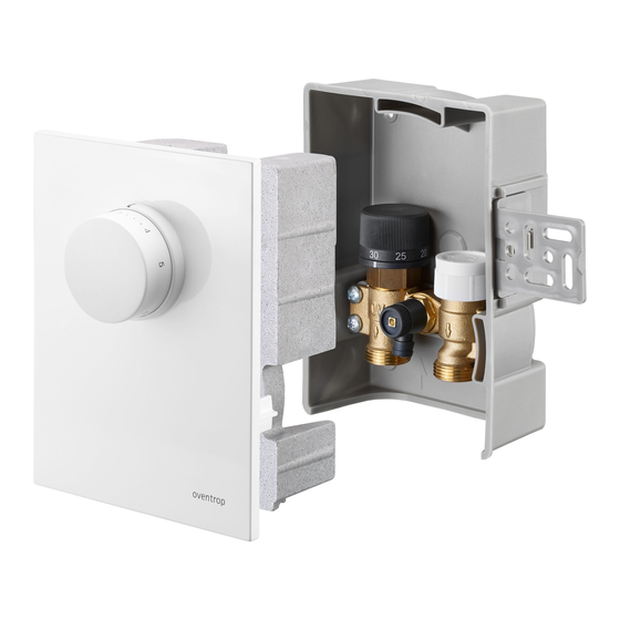
Die Anleitung muss am Einsatzort des Produk- tes verfügbar sein. f Geben Sie diese Anleitungen und alle mit- geltenden Anleitungen (z. B. Anleitung des Zubehörs) an den Betreiber weiter. Abb. 2: Aufbau „Unibox T RTL“ Befestigungswinkel Wandeinbaukasten Ventil mit voreinstellbarem Einsatz und integriertem Rücklauftemperaturbe- grenzer Entlüftungs- und Spülventil... -
Page 8: Maße
Stellung ca. 25°C und ca. 40°C. Abb. 3: Maße in mm 3.3 Funktionsbeschreibung Die „Unibox T RTL“ dient zur Einzelraumtem- peraturregelung und zur Begrenzung der Rück- lauftemperatur einer Flächentemperierung. Das integrierte Thermostatventil ist mit einem voreinstellbaren Ventileinsatz ausgestattet und Abb. -
Page 9: Thermostat Mit Fernversteller
Unibox T RTL Technische Beschreibung 3.5 Abdeckplatte mit Thermostat ACHTUNG mit Fernverstellung Beschädigung des Estrich durch Die Abdeckplatte mit Thermostat mit Fern- falsche Temperaturen! verstellung lässt sich stufenlos bis zu 20 mm f Befolgen Sie bei sämtlichen herausschieben. Estrichwerkstoffen die Festlegun- gen des Herstellers. -
Page 10: Technische Daten
Vor der Montage sollten Sie folgendes beach- Ersatzteile und Zubehör erhalten Sie im Fach- ten: handel. • Die Unterkante der „Unibox T RTL“ muss mindestens 20 cm über dem fertigen Fuß- Folgende Artikel können als Zubehör bezogen werden: boden liegen. -
Page 11: Montage „Unibox T Rtl
Unibox T RTL Montage 6.2 Montage „Unibox T RTL“ ACHTUNG Sachschaden durch Schmier- Die „Unibox T RTL“ muss sich mittel! immer am Ende des Flächentempe- rierungskreises befinden (siehe 3.3 Dichtungen können durch die Verwen- auf Seite 8). dung von Fetten oder Ölen zerstört werden. -
Page 12: Inbetriebnahme
Inbetriebnahme Unibox T RTL box T RTL“ in den Formschacht ein. 4. Nutzen Sie die beiliegenden Winkel (siehe 1.2 auf Seite 5) um die „Unibox T RTL“ im Formschacht auszurichten und zu befestigen. Abb. 10: Bauabdeckung aufsetzen 7.2 Vorarbeiten Funktionsheizen Führen Sie das Funktionsheizen durch um die... -
Page 13: Funktionsheizen
Die Mediumtemperatur des Flächentemperie- 2. Entfernen Sie die Bauschutzkappe. rungskreises stellen Sie am Handrad im Innern der „Unibox T RTL“ ein (siehe 3.4.1 auf Seite 3. Schrauben Sie den Stellkolben (siehe Abb. 8). Die Raumtemperatur stellen Sie am 2 auf Seite 7 (8)) auf das Ventil. Führen Thermostat mit Fernverstellung ein. -
Page 14: Störungen Beheben
Störungen beheben Unibox T RTL Störungen beheben STÖRUNG URSACHE BEHEBUNG Die Flächentemperierung wird Die „Unibox T RTL“ ist im Tauschen Sie das Innenleben nicht warm. Vorlauf eingebaut. der „Unibox T RTL“ durch das Innenleben der „Unibox ET“ (Art.-Nr. 1022632). Abb. 12: „Unibox T RTL“ im... -
Page 15: Instandhaltung
Unibox T RTL Instandhaltung 10. Instandhaltung Prüfen Sie die Dichtheit und Funktion der Ar- matur und ihrer Verbindungsstellen im Rahmen der Anlagenwartung regelmäßig. 11. Demontage und Entsorgung 11.1 Entsorgung ACHTUNG Verschmutzungsgefahr für die Umwelt! Nicht fachgerechte Entsorgung (z. B. im Hausmüll) kann zu Umweltschäden führen. -
Page 16: Anhang
Abb. 13: Anschlussschema zwei Heizkreise mit „Duo-An- schlussstück“ Wie viel m² Flächentemperie- Pro „Unibox T RTL“ können Sie ca. 20 m² Fläche anschließen. rung kann ich an die „Unibox Die Rohrlänge darf max. 100 m betragen bei einem 17er Rohr. -
Page 17: Abb. 14: Anschluss Mit Bypass-Ventil Und Heizkörperverschraubung Mit Bypass
Unibox T RTL Anhang FRAGE ANTWORT Kann ich die „Unibox T RTL“ Die „Unibox T RTL“ ist für Einrohrheizungsanlagen geeignet. auch bei einer Einrohrheizung Möglichkeit 1: verwenden? Abb. 14: Anschluss mit Bypass-Ventil und Heizkörperver- schraubung mit Bypass Bypass-Ventil Heizkörperverschraubung mit Bypass - Der Volumenstrom und Druckverlust können sich erhöhen. -
Page 18: Abb. 16: Anschluss Mit „Unibox Rla
Anhang Unibox T RTL FRAGE ANTWORT - Der Volumenstrom und Druckverlust können sich erhöhen. - Beachten Sie die Druckverlust und Geräuschkennlinie der Heizkörperarmaturen. - Regulieren Sie das Bypass-Ventil so ein, dass genug Wasser durch die Flächentemperierung fließt. - Bei geschlossenem Ventil dürfen am Heizkörper keine Ge- räusche entstehen. -
Page 19: Druckverlustdiagramm
Unibox T RTL Anhang 12.2 Druckverlustdiagramm Druckverlustdiagramm „Unibox T RTL“ mit Ventileinsatz der „Baureihe AV9“ bei 2 K P-Abwei- chung, RTL voll geöffnet. Voreinstellung kv-Wert 0,05 0,09 0,12 0,18 0,22 0,28 0,38 0,49 0,57 102273380-V01.06.2019... -
Page 20: Abbildungsverzeichnis
Abb. 10: Bauabdeckung aufsetzen ....................12 Abb. 11: Abdeckplatte mit Handrad aufsetzen ................13 Abb. 12: „Unibox T RTL“ im Vorlauf eingebaut ................14 Abb. 13: Anschlussschema zwei Heizkreise mit „Duo-Anschlussstück“ ........16 Abb. 14: Anschluss mit Bypass-Ventil und Heizkörperverschraubung mit Bypass ....... 17 Abb. -
Page 21: Glossar
Unibox T RTL Glossar 14. Glossar Bypass-Ventil Ein Bypass-Ventil ist ein Absperr- oder Drosselventil, das eingesetzt wird um ein anderes Bauteil zu umgehen. Das Bypassventil ist in einer Leitung verbaut, welche das andere Bauteil umgeht. Mit dem Einbau dieses Ventils werden verschiedene Ziele verfolgt: •... - Page 23 Accessories and spare parts ................30 Transport and storage ...................30 Installation ......................30 General installation advice ....................30 “Unibox T RTL” installation ..................... 31 Commissioning ....................32 Filling, bleeding and leak testing ..................32 Preliminary work for incremental heating test ..............32 102273380-V01.06.2019...
- Page 24 Inhaltsverzeichnis Unibox T RTL Incremental heating test ....................33 Cover plate featuring thermostat with remote control ............ 33 Operation ......................33 Troubleshooting .....................34 Maintenance ....................35 Removal and disposal ...................35 11.1 Disposal ........................... 35 Appendix ......................36 12.1 FAQs ..........................36 12.2 Pressure loss chart ......................39 Illustration index .....................40...
-
Page 25: General Information
Safety-related information 2.1 Normative directives Observe the legal requirements applicable at the installation location. The current standards, regulations and guide- lines apply. • DIN EN 1264 • DIN 18380 • VDI 2035 Illustr. 1: Protection cover on “Unibox T RTL” 102273380-V01.06.2019... -
Page 26: Correct Use
2.5.1 Danger caused by inadequately ensure the temperature balance of floor and qualified personnel wall surfaces in individual rooms. Moreover, the “Unibox T RTL” is used for individual room Work on this product may only be carried out temperature control. by appropriately qualified installers. Any other use of the product will be considered Sanitary, heating and air-conditioning incorrect use. -
Page 27: Risk Of Burns Due To Hot Components And Surfaces
Hand these operating instructions and all other relevant documents (e.g. accessory manuals) over to the user. Illustr. 2: “Unibox T RTL” construction Fixing bracket Wall box unit Valve with presettable insert and inte-... -
Page 28: Dimensions
The recommended control range is between approximately 25 °C and approximately 40 °C. Illustr. 3: Dimensions in mm 3.3 Functional description The “Unibox T RTL” is intended for individual room temperature control and for limiting the return temperature for a surface temperature Illustr. 4: Handwheel balance. -
Page 29: Thermostat With Remote Control
Unibox T RTL Technical description 3.5 Cover plate featuring NOTICE thermostat with remote Damage to the screed as a re- control sult of incorrect temperatures! The cover plate featuring thermostat with f Observe the instructions of the remote control can be smoothly extended up to screed manufacturer. -
Page 30: Technical Data
6.1 General installation advice ture Note the following prior to installation: Accessories and spare • The lower edge of the “Unibox T RTL” must be at least 20 cm above the finished floor. parts • The front edge of the “Unibox T RTL” must Spare parts and accessories are available from be level with the finished wall. -
Page 31: Unibox T Rtl" Installation
Screed 3. Remove the protection cover of the valve Protective tube (separate accessory) and the front cover of the pipe conduit unit (you must refit the protection cover and front cover after commissioning) and insert the “Unibox T RTL” into the pipe conduit unit. 102273380-V01.06.2019... -
Page 32: Commissioning
DIN EN 1264. plastering. 4. Reposition the protection cover of the Start the incremental heating test at the earli- “Unibox T RTL” (see Illustr. 1 on page 25) est: and the front cover of the pipe conduit unit. • 21 days after laying of concrete screed • 7 days after laying of calcium sulphate screed 102273380-V01.06.2019... -
Page 33: Incremental Heating Test
2. Remove the protection cap. temperature balance circuit on the handwheel 3. Screw the control piston (see Illustr. 2 on inside the “Unibox T RTL” (see 3.4.1 on page page 27 (8)) onto the valve. Direct the 28). Set the room temperature on the ther- capillary downwards. -
Page 34: Troubleshooting
Surface temperature balance The “Unibox T RTL” is in- Swap the inner components does not get warm. stalled in the supply. of the “Unibox T RTL” with the inner components of the “Uni- box ET” (Item no. 1022632). Illustr. 12: “Unibox T RTL” installed in the... -
Page 35: Maintenance
Unibox T RTL Maintenance 10. Maintenance Regularly check the seal tightness and function of the fitting and its connection points as part of system maintenance. 11. Removal and disposal 11.1 Disposal NOTICE Risk of environmental pollution! Incorrect disposal (for instance with standard waste) may lead to environ- mental damage. -
Page 36: Appendix
Is it possible to connect two Yes, use a “Duo connection piece” to connect two heating heating circuits to a “Unibox circuits of the same size to one “Unibox T RTL”. Each surface T RTL”? temperature balance circuit may have a maximum pipe length of 80 m, provided you use 16/17 mm pipes. - Page 37 Appendix QUESTION RESPONSE Can I also use the “Unibox The “Unibox T RTL” is suitable for a one pipe heating system. T RTL” in a one pipe heating Option 1: system? Illustr. 14: Connection with bypass valve and radiator fitting...
- Page 38 Appendix Unibox T RTL QUESTION RESPONSE - The volume flow and pressure loss may increase. - Observe the pressure loss and noise characteristic line of the radiator fittings. - Adjust the bypass valve so that a sufficient amount of water flows through the surface temperature balance circuit. - No noise must be perceivable when the valve is closed. Option 3: Illustr. 16: Connection with “Unibox RLA”...
-
Page 39: Pressure Loss Chart
Unibox T RTL Appendix 12.2 Pressure loss chart Pressure loss chart for “Unibox T RTL” with “Series AV9” valve insert at 2 K P-deviation, RTL fully opened. Presetting kv factor 0.05 0.09 0.12 0.18 0.22 0.28 0.38 0.49 0.57 102273380-V01.06.2019... -
Page 40: Illustration Index
Illustration index Unibox T RTL 13. Illustration index Illustr. 1: Protection cover on “Unibox T RTL” ................25 Illustr. 2: “Unibox T RTL” construction ..................27 Illustr. 3: Dimensions in mm ......................28 Illustr. 4: Handwheel ........................28 Illustr. 5: Cover plate not extended ....................29 Illustr. -
Page 41: Glossary
Unibox T RTL Glossary 14. Glossary Bypass valve A bypass valve is a shutoff or throttling valve that is used to bypass another component. The bypass valve is installed in a pipe that bypasses the other component. Installing such a valve has the following purpose: •... - Page 43 Unibox T RTL Inhaltsverzeichnis Contenu Page Généralités......................45 Validité de la notice d'utilisation ..................45 Composants fournis ......................45 Contact ..........................45 Protection de la propriété intellectuelle ................45 Déclaration de conformité ....................45 Symboles utilisés......................46 Informations relatives à la sécurité ..............46 Prescriptions normatives ....................
- Page 44 Inhaltsverzeichnis Unibox T RTL Mise en chauffe ....................... 53 Capot avec thermostat à commande à distance ............53 Service ......................53 Réparation des dysfonctionnements ............54 Maintenance ....................55 Démontage et élimination ................55 11.1 Élimination ........................55 Annexe ......................56 12.1 Questions fréquentes ...................... 56 12.2...
-
Page 45: Généralités
1.5 Déclaration de conformité Par la présente, la société Oventrop GmbH & Co. KG déclare que ce produit est en conformi- té avec les exigences fondamentales et les dis- positions applicables des directives juridiques UE concernées. -
Page 46: Symboles Utilisés
Informations relatives à la sécurité Unibox T RTL 1.6 Symboles utilisés 2.3 Modifications sur le produit Les modifications sur le produit sont interdites. Toute modification sur le produit entraîne Informations et explications utiles. l'annulation de la garantie. Le fabricant décline toute responsabilité en cas de dommages et dysfonctionnements résultant de modifications Appel à l'action sur le produit. -
Page 47: Risque De Blessure Lié À Des Travaux Non Conformes
Au besoin, recouvrir les ouvertures de purge avec un chiffon. f Remplacer immédiatement les robinetteries défectueuses. Fig. 2: Configuration de l'« Unibox T RTL » f Porter des lunettes de protection. 2.5.4 Risque de brûlure lié aux Équerre de fixation robinetteries et surfaces Boîtier encastrable... -
Page 48: Dimensions
Description technique Unibox T RTL 3.2 Dimensions fluide du système de régulation de température de surfaces à l'aide de la poignée manuelle. Le limiteur de la température de retour intégré dans le robinet mesure la température du fluide circulant, et ouvre ou ferme le robinet en conséquence. La plage de réglage recomman- dée se situe entre 25 °C et 40 °C environ. -
Page 49: Thermostat Avec Commande À Distance
Unibox T RTL Description technique 3.5 Capot avec thermostat à AVIS commande à distance Endommagement de la chape Le capot avec thermostat à commande à dis- lié à des températures inadap- tance s'extrait progressivement jusqu'à 20 mm. tées ! f Respecter les consignes données par le fabricant de la chape. -
Page 50: Données Techniques
Accessoires et pièces de rechange Unibox T RTL 3.6 Données techniques Particules Au sec et à l'abri de la poussière Température de service 100 °C Influences Protégé des vibrations max. ts mécaniques mécaniques Pression de service max. 10 bar Rayonnement À... -
Page 51: Montage De L'" Unibox T Rtl
Unibox T RTL Montage 6.2 Montage de l'« Unibox T RTL » AVIS Dégâts matériels liés aux lubri- L'« Unibox T RTL » doit toujours se fiants ! trouver à la fin du circuit de régu- lation de température de surfaces Des graisses et de l'huile peuvent en- (voir 3.3, page 48). dommager les joints. f Ne pas utiliser de graisse ou d'huile lors du montage. -
Page 52: Mise En Service
7.2 Préparation de la mise en chauffe Procéder à la mise en chauffe pour vérifier le bon fonctionnement du système de régulation Fig. 9: « Unibox T RTL » avec équerres de température de surfaces. 5. Raccorder la tuyauterie du circuit de AVIS régulation de température de surfaces à Endommagement de la chape l'« Unibox T RTL ». -
Page 53: Mise En Chauffe
Unibox T RTL Service 7.3 Mise en chauffe Procédure de mise en chauffe : 1. Ouvrir complètement le robinet en ef- fectuant 1 rotation env. du capuchon de protection blanc et positionner la poignée manuelle noire sur la valeur de réglage max. Régler la température de départ à... -
Page 54: Réparation Des Dysfonctionnements
RTL » par les composants intérieurs de l'« Unibox ET » (réf. 1022632). Fig. 12: « Unibox T RTL » montée sur l'aller Problèmes au niveau de l'ins- Augmenter le débit du circula- tallation de chauffage ou du teur (si nécessaire). générateur de chaleur. -
Page 55: Maintenance
Unibox T RTL Maintenance 10. Maintenance Vérifier régulièrement le fonctionnement et l'étanchéité du produit et des points de raccor- dement lors de l'entretien de l'installation. 11. Démontage et élimination 11.1 Élimination AVIS Risque de pollution ! Une élimination non conforme (par ex. avec les déchets ménagers) peut en- traîner des dommages environnemen-... -
Page 56: Annexe
Annexe Unibox T RTL 12. Annexe 12.1 Questions fréquentes QUESTION RÉPONSE Deux circuits de chauffage Oui, deux circuits de chauffage de longueur identique peuvent peuvent-ils être raccordés à être raccordés à un même « Unibox T RTL » à l'aide d'une un même « Unibox T RTL » ? « pièce de raccordement - Duo ». Chaque circuit de régulation de température de surfaces peut avoir jusqu'à 80 m de lon- gueur de tube, si ce dernier a un diamètre de 16 ou 17 mm. Fig. 13: Schéma de raccordement de deux circuits de chauffage avec une « pièce de raccordement -... - Page 57 Unibox T RTL Annexe QUESTION RÉPONSE Est-il possible d'utiliser L'« Unibox T RTL » est compatible avec les installations de l'« Unibox T RTL » avec une chauffage monotubes. installation de chauffage Option 1 : monotube ? Fig. 14: Raccordement avec robinet bypass et raccord de radiateur avec bypass Robinet bypass Raccord de radiateur avec bypass - Le débit et la perte de charge peuvent augmenter.
- Page 58 Annexe Unibox T RTL QUESTION RÉPONSE - Le débit et la perte de charge peuvent augmenter. - Respecter les courbes caractéristiques de la perte de charge et des bruits de la robinetterie de radiateur. - Réajuster le robinet bypass pour qu'une quantité suffisante d'eau circule dans le système de régulation de température de surfaces.
-
Page 59: Diagramme Des Pertes De Charge
Unibox T RTL Annexe 12.2 Diagramme des pertes de charge Diagramme des pertes de charge « Unibox T RTL » avec mécanisme de la « gamme AV9 » pour écart P 2 K, RTL complètement ouvert. Préréglage Valeur Kv 0,05 0,09 0,12 0,18 0,22 0,28 0,38 0,49 0,57 102273380-V01.06.2019... -
Page 60: Liste Des Figures
Liste des figures Unibox T RTL 13. Liste des figures Fig. 1: Capot de protection sur l'« Unibox T RTL » ..............45 Fig. 2: Configuration de l'« Unibox T RTL » ................47 Fig. 3: Dimensions en mm ......................48 Fig. 4: Poignée manuelle ......................48 Fig. 5: Capot non extrait ......................49 Fig. 6: Capot extrait ........................ -
Page 61: Glossaire
Unibox T RTL Glossaire 14. Glossaire Robinet bypass Un robinet bypass est un robinet d'arrêt ou d'étranglement utilisé pour contourner un autre composant. Le robinet bypass est installé sur une conduite contournant l'autre composant. Ce robinet a plusieurs objectifs : • Garantir un débit minimal •... - Page 64 OVENTROP GmbH & Co. KG Paul-Oventrop-Straße 1 D-59939 Olsberg Telefon +49 (0) 29 62 82-0 Telefax +49 (0) 29 62 82-400 E-Mail mail@oventrop.de www.oventrop.com Internet 102273380 V01.06.2019...
Need help?
Do you have a question about the Unibox T RTL and is the answer not in the manual?
Questions and answers