Table of Contents
Advertisement
Quick Links
Advertisement
Table of Contents

Related Manuals for Forney 220 AC/DC


Summary of Contents for Forney 220 AC/DC
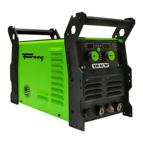
- Page 1 220 AC/DC STICK/TIG ARC WELDER OPERATING MANUAL ENGLISH ITEM# 421 REV 08.08.2019...
- Page 2 Above all, our employees will provide the same respect and caring attitude within the organization as they are expected to share with every Forney customer. Our goal will be to exceed our customers’ expectations through empowered people, guided by shared values and commitments.
- Page 3 TECHNICAL ISSUES? FORNEY CAN HELP! Thank you for choosing Forney! Please note: The store you purchased this m achine from DOES NOT handle product r eturns. F orney Industries will repair or replace defective products at no charge to you! When you call Forney's Technical Service department, you will speak to a trained product and application expert.
-
Page 4: Table Of Contents
Table of Contents WARRANTY ..................................3 TABLE OF CONTENTS ................................4 SYMBOLS LEGEND ................................5 SAFETY SUMMARY ................................5 PRINCIPAL SAFETY STANDARDS .............................5 CALIFORNIA PROPOSITION 65 WARNING ........................6 EMF INFORMATION ...............................6 PERSONAL PROTECTION ...............................6 FIRE PREVENTION ................................7 HIGH FREQUENCY RADIATION ............................8 ARC WELDING ................................8 ELECTRIC SHOCK ................................8 NOISE ...................................9 ADDITIONAL SAFETY INFORMATION ..........................9... -
Page 5: Symbols Legend
BEFORE INSTALLING, OPERATING OR CARRYING OUT MAINTENANCE ON THE MACHINE, READ THE CONTENTS OF THIS MANUAL CAREFULLY, PAYING PARTICULAR ATTENTION TO THE SAFETY RULES AND HAZARDS. In the event of these instructions not being clear, please contact your Forney Authorized Dealer or Forney Customer Service 1-800-521-6038. Symbols Legend MEANING... -
Page 6: California Proposition 65 Warning
• ANSI Z87.1 - SAFE PRACTICE FOR OCCUPATION AND EDUCATIONAL EYE AND FACE PROTECTION - Obtainable from the American National Standards Institute, 11 West 42nd St., New York, NY 10036 Telephone (212) 642-900, Fax (212) 398-0023 - www.ansi.org. • NFPA 51B: STANDARD FOR FIRE PREVENTION DURING WELDING, CUTTING, AND OTHER HOT WORK- Obtainable from the National Fire Protection Association, 1 Batterymarch Park, P.O. -
Page 7: Fire Prevention
welding area, either remove it or cover it with something non-flammable and non- reflective. Reflective arc rays can also cause skin burn in addition to eye injury. • Flying sparks can injure. Wear proper safety equipment to protect eyes and face. Shape tungsten electrode on grinder wearing proper protection and in a safe location. -
Page 8: High Frequency Radiation
• Keep cylinders upright and securely chain them to a fixed support to prevent tipping. • Keep cylinders away from areas where they may be subjected to physical damage or accidentally struck. Keep them a safe distance from any source of flame, sparks, or heat. •... -
Page 9: Noise
• Do not allow the welding equipment to come in contact with water or moisture. • Do not drag welding cables, TIG torch, electrode holder or welder INPUT POWER CABLE (8) through or allow them to come into contact with water or moisture. •... -
Page 10: Installation
Installation Welder Specifications Primary (Input) Volts 120VAC/230VAC Maximum Output 220A Phase Single Frequency 50/60Hz Recommended Circuit Breaker 50A for 230V or 30A for 120V Extension Cord Recommendations 230V- 3 conductor # 8AWG 120V -3 conductor #12AWG or larger up to 25 ft. Generator Requirements 230V -Minimum 10,000W continuous output with no low-idle function (or low-idle off), 5% THD Max. -
Page 11: Generators
Using the 230 volt – 120 volt Plug Adapter If a 230V (50A) circuit is not available, you can connect your 220 AC/DC Forney welder to 120V outlet (with a 30A breaker) using the plug adapter. When using the plug adapter, use lower power settings on the machine to avoid frequent circuit breaker trips. -
Page 12: Getting To Know Your Welder
Getting to Know Your Welder Description Your new single phase inverter welder offers Stick and TIG welding processes in the same power source. These processes can be selected with the process SELECTOR BUTTON on the front panel of the unit. TIG Welding In the TIG position, a TIG torch with a gas valve in the handle is NOT required. - Page 13 4. PULSE (% On) (6d): changes the amount of time the pulse stays at Main (Peak) current. A higher Pulse (% On) will increase penetration while a lower value is better for thin material. REAR VIEW OF FORNEY 220 AC/DC STICK/TIG ARC WELDER FRONT VIEW OF FORNEY 220 AC/DC STICK/TIG ARC WELDER...
-
Page 14: Operation
Operation Performance Data Plate and Duty Cycle On the machine, there is a plate that includes all the operating specifications for your new unit. The serial number of the product is also found on this plate. The duty cycle rating of a welder defines how long the operator can weld and how long the welder must rest and be cooled. -
Page 15: Welding Preparation
Secure the bare end of the welding electrode in-to the jaws of the electrode holder. • Switch the unit ON with the ON/OFF SWITCH. • Set the amperage with the AMPERAGE ADJUSTMENT KNOB. 220 AC/DC STICK SET-UP CHART Electrode E6010 E6011 E6013... - Page 16 Setup for TIG Welding (GTAW) Setting up the Equipment for TIG Welding (GTAW): Lanthanated Tungsten 1/16” to 1/8” (MAX) recommended for use. WARNING: TIG TORCH IS ALWAYS LIVE (ELECTRICALLY HOT). Use caution and ensure the TIG torch is not in contact with or near conductive or grounded materials. •...
-
Page 17: Gas Selection
Gas Selection Use 100% argon gas when TIG welding. Accessory Connection Guide This machine has a 7-pin Amphenol™ style connection for connecting accessories16 • Foot Pedal (adjusts amperage) – attach TIG torch to negative Dinse™ terminal and then plug in 7-pin foot pedal connector. -
Page 18: Maintenance & Servicing
A Good Starting Point for Aluminum TIG < 1/8 “ = 140 MAX Amperage 1/8 “ – 3 /16” = 170 MAX 1 /4” + = 200 MAX AC Freq 90 HZ AC Balance 70 % EN PULSE (HZ) PULSE ( % ON) Maintenance &... - Page 19 PROBLEM POSSIBLE CAUSE POSSIBLE SOLUTION Output short or abnormal voltage Make sure the MIG wire is not touching feedback. the grounded work piece. Make sure the TIG electrode is not FAULT CODE F09 DISPLAYED. touching the grounded work piece. Stick electrode stuck to work piece Make sure that your stick electrode is not stuck to the grounded work piece.
- Page 20 PROBLEM POSSIBLE CAUSE POSSIBLE SOLUTION Insufficient gas at weld area. Check that the gas is not being blown away by drafts and, if so, move to a more sheltered weld area. If not, check gas cylinder contents, gauge, regulator setting, and operation of gas valve.
- Page 21 Machine Parts Diagram & Replacement Parts List PART NUMBER ITEM DESCRIPTION Argon/Co2 Flow Meter 85364 85516 120-230 Volt Power Adapter Plug 85655 TIG Foot Pedal 85658 Standard TIG Torch 85668 Ground Clamp and Cable 85670 Electrode Holder with Cable 5084 Expert-Tech Tool WWW.FORNEYIND.COM...
-
Page 22: User Notes
User Notes _______________________________________________________________________________________________ ________________________________________________________________________________ ________________________________________________________________________________ ________________________________________________________________________________ ________________________________________________________________________________ ________________________________________________________________________________ ________________________________________________________________________________ ________________________________________________________________________________ ________________________________________________________________________________ ________________________________________________________________________________ ________________________________________________________________________________ ________________________________________________________________________________ ________________________________________________________________________________ ________________________________________________________________________________ ________________________________________________________________________________ ________________________________________________________________________________ ________________________________________________________________________________ ________________________________________________________________________________ ________________________________________________________________________________ ________________________________________________________________________________ ________________________________________________________________________________ ________________________________________________________________________________ ________________________________________________________________________________ ________________________________________________________________________________ ________________________________________________________________________________ ________________________________________________________________________________ ________________________________________________________________________________ ________________________________________________________________________________ ________________________________________________________________________________ ________________________________________________________________________________ ________________________________________________________________________________ ________________________________________________________________________________ ________________________________________________________________________________ ________________________________________________________________________________ ________________________________________________________________________________ ________________________________________________________________________________ ________________________________________________________________________________ ________________________________________________________________________________ ________________________________________________________________________________ ________________________________________________________________________________ ________________________________________________________________________________... - Page 23 User Notes _______________________________________________________________________________________________ ________________________________________________________________________________ ________________________________________________________________________________ ________________________________________________________________________________ ________________________________________________________________________________ ________________________________________________________________________________ ________________________________________________________________________________ ________________________________________________________________________________ ________________________________________________________________________________ ________________________________________________________________________________ ________________________________________________________________________________ ________________________________________________________________________________ ________________________________________________________________________________ ________________________________________________________________________________ ________________________________________________________________________________ ________________________________________________________________________________ ________________________________________________________________________________ ________________________________________________________________________________ ________________________________________________________________________________ ________________________________________________________________________________ ________________________________________________________________________________ ________________________________________________________________________________ ________________________________________________________________________________ ________________________________________________________________________________ ________________________________________________________________________________ ________________________________________________________________________________ ________________________________________________________________________________ ________________________________________________________________________________ ________________________________________________________________________________ ________________________________________________________________________________ ________________________________________________________________________________ ________________________________________________________________________________ ________________________________________________________________________________ ________________________________________________________________________________ ________________________________________________________________________________ ________________________________________________________________________________ ________________________________________________________________________________ ________________________________________________________________________________ ________________________________________________________________________________ ________________________________________________________________________________ ________________________________________________________________________________...
- Page 24 Forney Industries, Inc. 2057 Vermont Drive Fort Collins, CO 80525 +1-800-521-6038 www.forneyind.com...
Need help?
Do you have a question about the 220 AC/DC and is the answer not in the manual?
Questions and answers