Advertisement
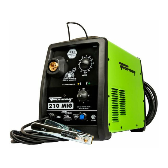
210 MIG WELDER
OWNER'S MANUAL
1
WWW.FORNEYIND.COM
CAT. #00311 WELDER FEATURES:
• 210 Amp Output / 230V Input
• For Steel, Stainless Steel, and Aluminum
welding
• Aluminum drive system and easy to
remove torch
• Optional spool gun increases flexibility
• Cable wrap
RELIABLE TECHNOLOGY:
• Easy to use, forgiving, increases productivity
• Rugged transformer with heavy duty
capacitors for smooth arc
• Simple to adjust and use
• Quality de-spooler that easily adapts
between 4" and 8" spools
IDEAL FOR:
General Fabrication, Auto Body, Farm & Ranch,
Sheet Metal, Contractor, and More...
INCLUDES:
Torch with 10' lead; 10' Ground Cable and Clamp;
15' Input Power Cable; Gas Hose and Regulator
Advertisement

Related Manuals for Forney 210 MIG


Summary of Contents for Forney 210 MIG
- Page 1 210 MIG WELDER OWNER’S MANUAL CAT. #00311 WELDER FEATURES: • 210 Amp Output / 230V Input • For Steel, Stainless Steel, and Aluminum welding • Aluminum drive system and easy to remove torch • Optional spool gun increases flexibility • Cable wrap RELIABLE TECHNOLOGY: •...
- Page 2 STOP PLEASE! DO NOT RETURN TO THE STORE If you have questions or problems with your new Welder, please call customer service at 1-800-521-6038 Monday through Friday from 7am-5pm Mountain Time or at www.forneyind.com/customer_service. Please take time to register your product at www.forneyind.com/customer_service/register_your_product/.
- Page 3 Above all, our employees will provide the same respect and caring attitude within the organization as they are expected to share with every Forney customer. Our goal will be to exceed our customers’ expectations through empowered people, guided by shared values and commitments.
-
Page 4: Warranty
Colorado, warrants to its original retail purchaser that the new Forney equipment sold after the effective date of this limited warranty is free of defects in material and workmanship at the time it is shipped by Forney. This is in lieu of all other warranties, express or implied. -
Page 5: Table Of Contents
TABLE OF CONTENTS WARRANTY ..........................4 TABLE OF CONTENTS ........................5 SAFETY INFORMATION ......................... 6 ASSEMBLY AND MAJOR COMPONENTS ..................11 FRONT PANEL OPERATION......................16 GENERAL OPERATING INSTRUCTIONS ..................17 TROUBLESHOOTING ........................19 SPARE PARTS AND DIAGRAMS ....................21 WWW.FORNEYIND.COM... -
Page 6: Safety Information
READ THE CONTENTS OF THIS MANUAL CAREFULLY, PAYING PARTICULAR ATTENTION TO THE SAFETY RULES AND HAZARDS. In the event of these instructions not being clear, please contact your Forney Authorized Dealer or Forney Customer Service 1-800-521-6038 Safety Information READ BEFORE USING Principal Safety Standards •... - Page 7 Personal Protection Welding processes of any kind can be dangerous not only to the operator but to any person situated near the equipment, if safety and operating rules are not strictly observed. Arc rays can injure your eyes and burn your skin. The welding arc produces very bright ultraviolet and infrared light.
- Page 8 Electric Shock WARNING: ELECTRIC SHOCK CAN KILL! • A person qualified in First Aid techniques should always be present in the working area; If a person is found unconscious and electric shock is suspected, do not touch the person if she or he is in contact with cable or electric wires.
- Page 9 Shielding Gas Cylinders contain gas under high pressure. If damaged, a cylinder can explode. Treat them carefully. • Arc welders use only inert or non-flammable gases for welding arc protection. It is important to choose the appropriate gas for the type of welding being performed. •...
- Page 10 Notes: • Periodically inspect supply cable for any cracks or exposed wires. If it is not in good condition, have it repaired by a Service Center. • Do not pull violently the input power cable to disconnect it from supply outlet. •...
-
Page 11: Assembly And Major Components
Assembly • Unpack the welder. • Assemble the plastic top handle using the screws provided. • Plug the torch hose into the socket on the front of the welder. • Attach the gas hose and the electrical connector. Torch Lead and Spool Gun Assembly Standard Gun or Torch Lead Spool Gun Gas Cylinder and Regulator Connection... - Page 12 Shielding Gas Guide Metal NOTE Mild Steel Argon + CO2 Argon controls spatter Argon + CO2 + Oxygen Oxygen improves arc stability Aluminum Argon Arc stability, good fusion and minimum splatter. Higher heat input suitable for heavy sections. Argon + Helium Minimum porosity.
- Page 13 • Loosen and lower the plastic knob (A) (Fig.5). Release the upper roll (B) of the feeder. Extract the wire from the torch liner. • When the wire is disconnected, grasp it with pliers so that it cannot exit from the spool. If necessary, straighten it before inserting it in the wire input guide (C).
- Page 14 How to Choose the Wire Liner for Direct and Euro Connection Torches • There are basically 2 types of wire liners: Steel wire liners and Teflon wire liners. • Steel wire liners can be coated or not coated. Coated wire liners are used for air cooled torches.
- Page 15 14. Flip the quick release drive tensioner back into position on the drive tensioner arm. 15. Tighten (turn clockwise) the drive tension adjusting knob until the tension roller is applying enough force on the wire to prevent it from slipping out of the drive assembly. 16.
-
Page 16: Front Panel Operation
Front Panel Operation Units may be used either with the standard torch (supplied with them) or with the Spool Gun. Welder Controls 1. Main ON/OFF switch and welding voltage adjustment: 2. Wire feed adjustment knob To increase the wire speed, turn the potentiometer clockwise;... -
Page 17: General Operating Instructions
General Operating Instructions Some experience is required to adjust and use a MIG welder. In MIG welding two parameters are fundamental: the welding voltage and the wire speed. The resulting welding current is a result of these two settings. • Set the voltage and wire feed controls to positions suitable for the thickness of the material to be welded. - Page 18 Technical Data Information Guide 1. Serial number of the unit 9. Protection degree 2. Welder model 10. Power 3. Type of characteristic 11. Size of the necessary main fuse 4. Min. - Max rated No Load Voltage 12. Supply current 5.
-
Page 19: Troubleshooting
Troubleshooting This chart will assist you in resolving common problems you may encounter. These are not all the possible solutions. PROBLEM POSSIBLE CAUSE POSSIBLE SOLUTION No “power” from welder. Input cable or plug malfunction. Check for proper input cable connection. Wrong size fuse. - Page 20 PROBLEM POSSIBLE CAUSE POSSIBLE SOLUTION Wire burns back to Contact tip clogged or damaged. Replace the contact tip. contact tip. Wire feed speed too slow. Increase wire speed. Wrong size contact tip. Use correct size contact tip. Bad connection from cable to Tighten clamp connection or clamp.
-
Page 21: Spare Parts And Diagrams
Tools and Spare Parts List NO. PART NUMBER ITEM DESCRIPTION QTY. NO. PART NUMBER ITEM DESCRIPTION QTY. 21690226K Door latch (1pc pack) 22910110 Male gas connector 1/8"gas - 5/8"unf 05000262 Left panel with silk screen and labels Inp.Power cable3x12awg4.5M+50a6- 20220173 50p plug 04600421 Kit spool holder with ring for 5kg spool... - Page 22 WWW.FORNEYIND.COM...
- Page 23 WWW.FORNEYIND.COM...
- Page 24 Torch/Gun Installation Front View Torch/Gun Installation Spool & Torch Assembly Complete Torch/Gun Consumable Assembly Gas Hose Connection Polarity Change Electrical Connector WWW.FORNEYIND.COM...
- Page 25 Spool Installation Loosen tension knob & lift roller Install wire Lock in roller and correctly set tension WWW.FORNEYIND.COM...
- Page 26 MIG Gun Torch Spare Parts List NO. PART NUMBER ITEM DESCRIPTION QTY. NO. PART NUMBER ITEM DESCRIPTION QTY. 23005373K Tweco torch nozzle 21-50f 1 pc pack 23005376K Black handle for m15 torch 1 pc pack 23005018K 0,6Mm contact tip for t1.4-1.6 10 pc pack 10 23005362K Screws for m25 torch handle 12 pcs pack 12 23005019K...
- Page 27 Spool Gun Torch Spare Parts List NO. PART NUMBER ITEM DESCRIPTION QTY. NO. PART NUMBER ITEM DESCRIPTION QTY. 01 23005147K Torch gas nozzle tw1 mc-31 5 pcs pack 5 Fast conn.For hose d.4 M6x0,75 2 21 22910001K pcs pack 02 23005331K Contact tip d.0,8 Al t1.4 10 pc pack 22 04600143 Wire feeding motor d.28 + Pinion...
- Page 28 Forney Industries, Inc. 1830 LaPorte Avenue Fort Collins, CO 80526 800-521-6038 www.forneyind.com WWW.FORNEYIND.COM...
Need help?
Do you have a question about the 210 MIG and is the answer not in the manual?
Questions and answers