Table of Contents
Advertisement
OWNER'S MANUAL
1
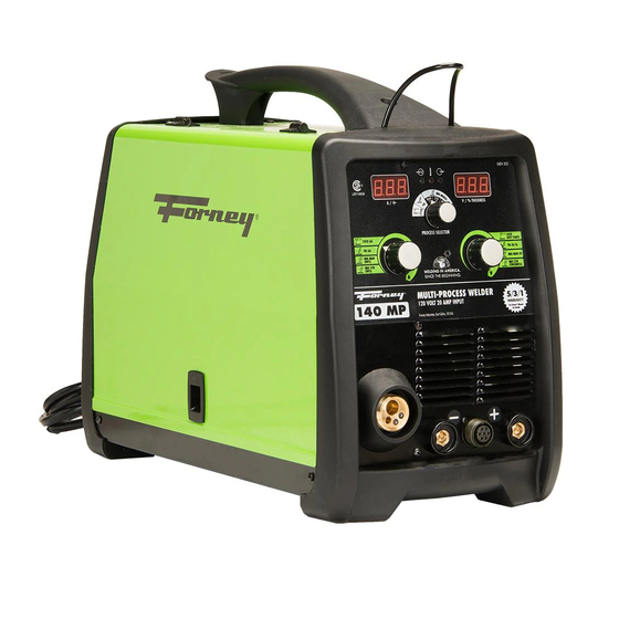
140 MP
WWW.FORNEYIND.COM
CAT#00322 MULTI-PROCESSOR
FEATURES:
• A Multi-Process inverter machine capable of
MIG, Stick, or TIG Welding
• Power saving and versatile inverter technology
allows for use with 115V (20A OR 15A input)
• Welding range up to 140 Amps
• Can be used for Steel, Stainless Steel, and
Aluminum
• Easy to change between welding processes
• 12' Premium MIG torch with Euro disconnect
and Tweco
style consumables
®
RELIABLE TECHNOLOGY:
• Advanced synergic electronics allow for
outstanding arc control for all processes
• Metallic heavy-duty wire drive system
• Optional spool gun increases flexibility
• Large cabinet with easy access to 4" and 8"
spools
• Digital readouts
IDEAL FOR:
General Fabrication, Auto Body, Farm & Ranch,
Maintenance, Sheet Metal, Contractor, and More...
INCLUDES:
MIG Torch with 12' lead; Ground Cable and Clamp;
Stick Electrode Holder; 8' Power Cable; Gas Hose and
Regulator
LR114649
Advertisement
Table of Contents

Related Manuals for Forney 140 MP


Summary of Contents for Forney 140 MP
- Page 1 140 MP OWNER’S MANUAL CAT#00322 MULTI-PROCESSOR FEATURES: • A Multi-Process inverter machine capable of MIG, Stick, or TIG Welding • Power saving and versatile inverter technology allows for use with 115V (20A OR 15A input) • Welding range up to 140 Amps •...
- Page 2 STOP PLEASE! DO NOT RETURN TO THE STORE If you have questions or problems with your new Welder, please call customer service at 1-800-521-6038 Monday through Friday from 7am-5pm Mountain Time or at www.forneyind.com/customer_service. Please take time to register your product at www.forneyind.com/customer_service/register_your_product/.
- Page 3 Above all, our employees will provide the same respect and caring attitude within the organization as they are expected to share with every Forney customer. Our goal will be to exceed our customers’ expectations through empowered people, guided by shared values and commitments.
-
Page 4: Warranty
Colorado, warrants to its original retail purchaser that the new Forney equipment sold after the effective date of this limited warranty is free of defects in material and workmanship at the time it is shipped by Forney. This is in lieu of all other warranties, express or implied. -
Page 5: Table Of Contents
TABLE OF CONTENTS WARRANTY ..........................4 TABLE OF CONTENTS ........................5 SAFETY PRECAUTIONS ........................6 INSTALLATION RECOMMENDATIONS ..................... 9 ASSEMBLY ..........................11 FRONT PANEL OPERATION......................12 GENERAL OPERATION INSTRUCTIONS ..................16 TROUBLESHOOTING ........................26 SPARE PARTS AND DIAGRAMS ....................27 WWW.FORNEYIND.COM... - Page 6 READ THE CONTENTS OF THIS MANUAL CAREFULLY, PAYING PARTICULAR ATTENTION TO THE SAFETY RULES AND HAZARDS. In the event of these instructions not being clear, please contact your Forney Authorized Dealer or Forney Customer Service 1-800-521-6038 Safety Information READ BEFORE USING Principal Safety Standards •...
- Page 7 Personal Protection Welding processes of any kind can be dangerous not only to the operator but to any person situated near the equipment, if safety and operating rules are not strictly observed. Arc rays can injure your eyes and burn your skin. The welding arc produces very bright ultra violet and infra red light.
- Page 8 Electric Shock WARNING: ELECTRIC SHOCK CAN KILL! • A person qualified in First Aid techniques should always be present in the working area; If a person is found unconscious and electric shock is suspected, do not touch the person if she or he is in contact with cable or electric wires.
-
Page 9: Installation Recommendations
Protective Welding Gases Shielding gas cylinders contain gas under high pressure. If damaged, a cylinder can explode. Treat them carefully. • These welders use only inert or non-flammable gases for welding arc protection. It is important to choose the appropriate gas for the type of welding being performed; •... - Page 10 Notes: • Periodically inspect supply cable for any cracks or exposed wires. If it is not in good conditions, have it repaired by a Service Centre. • Do not pull violently the input power cable to disconnect it from supply. •...
-
Page 11: Assembly
Assembly • Unpack the welder; • Assemble the plastic handle on torch wrap using the screws provided. Torch Lead and Spool Gun Assembly • Attach the standard MIG welding torch to the threaded connection on the front of the welder. •... -
Page 12: Front Panel Operation
Controls and Operational Features CAT# 322 PROCESS SELECTOR STICK STICK (A) (HOT START) TIG (A) TIG (N/A) MIG MAN MIG MAN (V) (WFS) MIG SYN MIG SYN (WFS) (THICKNESS) MULTI-PROCESS WELDER 120 VOLT 20 AMP INPUT Forney Industries, Fort Collins, CO USA WWW.FORNEYIND.COM... - Page 13 2T / 4T EXPLANATION: 2T: Press the torch trigger to weld. Welding continues until the trigger is released. 4T: Press the torch trigger and immediately release the trigger, welding will start and continue until the torch trigger is pressed and released a second time. The 4T function is useful when doing long welds and in some automatic welding operations where the torch may be mounted in a fixture.
- Page 14 7. Right Knob: It is used to adjust the following welding parameters: a. in STICK, “SMAW”Mode it adjusts the over-current value of the electric arc (Hot Start), variable from 0 to 50% on the current value adjusted with the Left Knob (8). b.
- Page 15 FIGURE 3 16. 2 roll Aluminum wire feeder 17. Slope up Time regulation potentiometer 18. Burn Back Time Regulation potentiometer (B.B.T.) 19. Polarity Change Terminals for the Euro Socket: a. positive polarity for MIG Welding, “GMAW”; b. negative polarity for FLUXCORE WIRE Welding, “FCAW” 20.
- Page 16 General Operating Instructions This manual was edited to give some indications on the operation of the welder and was thought to offer information for its practical and safe use. Its purpose is not to teach welding techniques. All suggestions are indicative and intended to be only guide lines. To ensure that your welder is in good conditions, inspect it carefully when you remove it from its packing having care to ascertain that the cabinet or the stocked accessories are not damaged.
- Page 17 7-pin connector (12). The over-current value of the electric arc (Hot Start) with the Right Knob (7). Adjustable Welding current: 120V input voltage: Min 20 Amp - Max 80 Amp 140 MP STICK SET-UP CHART ELECTRODE DIAMETER MATERIAL ELECTRODE 1/16”...
- Page 18 • Press the torch trigger or the foot control and then lift the tungsten electrode away from the work piece. REMEMBER to turn OFF the gas immediately after you finish welding. 140 MP TIG SET-UP CHART MATERIAL THICKNESS TUNGSTEN 22 Gauge...
- Page 19 MIG, “GMAW” - Fluxcore wire, “FCAW” Welding Torch Connection • Plug the torch hose into the socket on the front of the welder having care to not damage the contacts and secure by hand screwing in the threaded connection. Wire Loading Ensure the gas and electrical supplies are disconnected.
- Page 20 Replacing the Wire Liner Ensure the gas and electrical supplies are disconnected. • Disconnect the torch from the machine. • Place it on a flat surface and carefully remove the brass nut (1). • Pull the liner out of the hose. •...
- Page 21 MIG, “GMAW”, Fluxcore Wire, “FCAW” Manual Welding Before connecting the unit to the mains, verify that all the accessories are correctly installed and mounted for electric welding (torch, wire spool etc ...). • Select Manual MIG (2T or 4T) Welding function with the Selector Switch (6) on the front panel. Select either the 2-Step or 4-Step function of the torch trigger.
- Page 22 potentiometer located inside the access panel (17). 2. At the end of the the Slope-Up Time, the wire feed speed reaches the value adjusted with the Left knob (8). • To stop welding, release the trigger. The arc stays ON accordingly to the set B.B.T. (Burn back time).
- Page 23 Then push it across the drive roller and into the gun assembly about 6”. 13. Line the wire up in the top groove of the drive roller, then push the drive tension arm against the drive roller. 14. Flip the quick release drive tensioner back into position on the drive tensioner arm. 15.
- Page 24 4. Push the casing and the gun back together. 5. With a flat tipped screwdriver, tighten the screw which connects the spool casing to t 140 MP MIG SET-UP CHART MATERIAL THICKNESS 22 Gauge...
-
Page 25: Troubleshooting
Troubleshooting This chart will assist you in resolving common problems you may encounter. These are not all the possible solutions. PROBLEM POSSIBLE CAUSE POSSIBLE SOLUTION No “power” from welder. Input cable or plug malfunction. Check for proper input cable connection. Wrong size fuse. - Page 26 PROBLEM POSSIBLE CAUSE POSSIBLE SOLUTION Wire burns back to Contact tip clogged or damaged. Replace the contact tip. contact tip. Wire feed speed to slow. Increase wire speed. Wrong size contact tip. Use correct size contact tip. Bad connection from cable to Tighten connection or replace clamp.
- Page 27 Kit spool holder with ring for 5kg spool 77650399 Front panel label 140mp 22200020 Switch 3a 05000269 Front panel 140mp forney w/silk screen 21690737 Knob Fem.Dinse plug 25sqmm cx30 (1 pc 33740582 22100002K Metal box for front panel pcb protection...
- Page 28 WWW.FORNEYIND.COM...
- Page 29 MIG Gun Torch Spare Parts List PART PART ITEM DESCRIPTION QTY. ITEM DESCRIPTION QTY. NUMBER NUMBER 23005373K Tweco torch nozzle 21-50f 1 pc pack 23005362K Screws for m25 torch handle 12 pc pack 23005018K 0,6Mm contact tip for t1.4-1.6 10 Ppc pack 10 23005535 Coax cable 14mm2 3m 1 pc pack 23005019K...
- Page 30 WWW.FORNEYIND.COM...
- Page 31 WWW.FORNEYIND.COM...
- Page 32 Forney Industries, Inc. 1830 LaPorte Avenue Fort Collins, CO 80526 800-521-6038 www.forneyind.com WWW.FORNEYIND.COM...
Need help?
Do you have a question about the 140 MP and is the answer not in the manual?
Questions and answers
I have a forney easy weld 140 fc-i and I conect I 220 volt and fron tha day they didn't work and I'm looking for a new panel, I lake tha little machine
The document does not mention the Forney Easy Weld 140 FC-I specifically, but it lists parts for the Forney 140 MP. If you need a replacement panel, you can check the listed panels such as the "Front panel 140mp forney w/silk screen" or the "Right cover panel with silk screen." To find the correct part for your model, contact Forney Industries customer service at 1-800-521-6038 or visit www.forneyind.com.
This answer is automatically generated