Advertisement
Quick Links
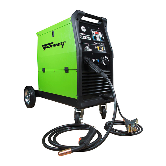
270 MIG WELDER
OWNER'S MANUAL
1
WWW.FORNEYIND.COM
CAT. #00319 WELDER FEATURES:
• 270 Amp Output / 230V Input
• For Steel, Stainless Steel, and Aluminum
welding
• Heavy duty torch
• Aluminum drive system
ADVANCED TECHNOLOGY:
• Easy to use, forgiving, increases
productivity
• Digital readout for true amps
• Three trigger modes with spot weld timer
• Optional spool gun increases flexibility
• Burn back and slope control
IDEAL FOR:
General Fabrication, Auto Body, Farm & Ranch,
Sheet Metal, Contractor, and More...
INCLUDES:
Torch with 10' lead; 10' Ground Cable and Clamp;
15' Input Power Cable; Gas Hose and Regulator
Advertisement

Related Manuals for Forney 270 MIG


Summary of Contents for Forney 270 MIG
- Page 1 270 MIG WELDER OWNER’S MANUAL CAT. #00319 WELDER FEATURES: • 270 Amp Output / 230V Input • For Steel, Stainless Steel, and Aluminum welding • Heavy duty torch • Aluminum drive system ADVANCED TECHNOLOGY: • Easy to use, forgiving, increases productivity •...
- Page 2 STOP PLEASE! DO NOT RETURN TO THE STORE If you have questions or problems with your new Welder, please call customer service at 1-800-521-6038 Monday through Friday from 7am-5pm Mountain Time or at www.forneyind.com/customer_service. Please take time to register your product at www.forneyind.com/customer_service/register_your_product/.
- Page 3 Above all, our employees will provide the same respect and caring attitude within the organization as they are expected to share with every Forney customer. Our goal will be to exceed our customers’ expectations through empowered people, guided by shared values and commitments.
-
Page 4: Warranty
Colorado, warrants to its original retail purchaser that the new Forney equipment sold after the effective date of this limited warranty is free of defects in material and workmanship at the time it is shipped by Forney. This is in lieu of all other warranties, express or implied. -
Page 5: Table Of Contents
TABLE OF CONTENTS WARRANTY ..........................4 TABLE OF CONTENTS ........................5 SAFETY INFORMATION ......................... 6 ASSEMBLY AND MAJOR COMPONENTS ..................11 FRONT PANEL OPERATION......................16 GENERAL OPERATING INSTRUCTIONS ..................17 TROUBLESHOOTING ........................20 SPARE PARTS AND DIAGRAMS ....................22 WWW.FORNEYIND.COM... -
Page 6: Safety Information
READ THE CONTENTS OF THIS MANUAL CAREFULLY, PAYING PARTICULAR ATTENTION TO THE SAFETY RULES AND HAZARDS. In the event of these instructions not being clear, please contact your Forney Authorized Dealer or Forney Customer Service 1-800-521-6038 Safety Information READ BEFORE USING Principal Safety Standards •... - Page 7 Personal Protection Welding processes of any kind can be dangerous not only to the operator but to any person situated near the equipment, if safety and operating rules are not strictly observed. Arc rays can injure your eyes and burn your skin. The welding arc produces very bright ultraviolet and infrared light.
- Page 8 Electric Shock WARNING: ELECTRIC SHOCK CAN KILL! • A person qualified in First Aid techniques should always be present in the working area; If a person is found unconscious and electric shock is suspected, do not touch the person if she or he is in contact with cable or electric wires.
- Page 9 Protective Welding Gases Shielding Gas Cylinders contain gas under high pressure. If damaged, a cylinder can explode. Treat them carefully. • Arc welders use only inert or non-flammable gases for welding arc protection. It is important to choose the appropriate gas for the type of welding being performed. •...
- Page 10 • Do not squash the supply cable with other machines. It could be damaged and cause electric shock. • Keep the supply cable away from heat sources, oils, solvents or sharp edges. • In case you are using an extension cord, try to keep it straight, and untangled to avoid overheating.
-
Page 11: Assembly And Major Components
Assembly Handle and Wheels Assembly (FIG.2) • Unpack the welder. • Screw the two casters (D) to the machine. • Insert the axle (A) through the holes at the rear of the welder and slide a wheel (B) on to each end followed by the retaining washers (C). - Page 12 Shielding Gas Guide Metal NOTE Mild Steel Argon + CO2 Argon controls spatter Argon + CO2 + Oxygen Oxygen improves arc stability Aluminium Argon Arc stability, good fusion and minimum spatter. Higher heat input suitable for heavy sections. Argon + Helium Minimum porosity.
- Page 13 • Loosen and lower the plastic knob (A) (Fig.5). Release the upper roll (B) of the feeder. Extract the wire from the torch liner. • When the wire is disconnected, grasp it with pliers so that it cannot exit from the spool. If necessary, straighten it before inserting it in the wire input guide (C).
- Page 14 How to Choose the Wire Liner for Direct and Euro Connection Torches • There are basically 2 types of wire liners: Steel wire liners and Teflon wire liners. • Steel wire liners can be coated or not coated. Coated wire liners are used for air cooled torches.
- Page 15 14. Flip the quick release drive tensioner back into position on the drive tensioner arm. 15. Tighten (turn clockwise) the drive tension adjusting knob until the tension roller is applying enough force on the wire to prevent it from slipping out of the drive assembly. 16.
-
Page 16: Front Panel Operation
Front Panel Operation With welders in the digital series, thanks to a special electronic card it is possible to adjust externally the main welding parameters. The main purpose of these units is to make adjustment of these parameters very easy. The microprocessor control handles the functions of the p.c.board that are viewed by means of LED’s while a digital display shows the parameters set and welding current. -
Page 17: General Operating Instructions
Welding Preparation • Connect the ground cable to the proper female outlet on the bottom right-hand corner of the welder (on some models the ground cable is already connected). Attach the ground clamp to the bare metal to be welded, making sure of good contact; •... - Page 18 The display can view numbers from 1 to 99 (1 being the minimum value and 99 the maximum value). The display shows the real welding current and the value of the parameter you selected and adjusted during the regulation phase. After welding the display will view the welding current value for a maximum of 5 seconds.
- Page 19 Welding Hints and Maintenance • Always weld clean, dry and well prepared material. • Hold gun at a 45° angle to the workpiece with nozzle about 1/2” from the surface. • Move the gun smoothly and steadily as you weld. •...
-
Page 20: Troubleshooting
Troubleshooting This chart will assist you in resolving common problems you may encounter. These are not all the possible solutions. PROBLEM POSSIBLE CAUSE POSSIBLE SOLUTION No “power” from welder. Input cable or plug malfunction. Check for proper input cable connection. Wrong size fuse. - Page 21 PROBLEM POSSIBLE CAUSE POSSIBLE SOLUTION Wire burns back to Contact tip clogged or damaged. Replace the contact tip. contact tip. Wire feed speed too slow. Increase wire speed. Wrong size contact tip. Use correct size contact tip. Bad connection from cable to Tighten clamp connection or clamp.
-
Page 22: Spare Parts And Diagrams
Tools and Spare Parts List NO. PART NUMBER ITEM DESCRIPTION QTY. NO. PART NUMBER ITEM DESCRIPTION QTY. 22710083 CONTROL PC BOARD HE-IND30V 38 22600043 SHUNT FOR AMMETER 300A 60MV 02 04600147 MP48 MOTOR + PINION 39 44135173 CHOKE ø8 40X85AL 03 22315003 CAPACITOR 63V TRANSFORMER 60HZ 230V... - Page 23 WWW.FORNEYIND.COM...
- Page 24 WWW.FORNEYIND.COM...
- Page 25 WWW.FORNEYIND.COM...
- Page 26 MIG Gun Torch Spare Parts List NO. PART NUMBER ITEM DESCRIPTION QTY. NO. PART NUMBER ITEM DESCRIPTION QTY. TWECO TORCH NOZZLE 22-50 1 PC TW2 62A-45 TORCH NECK 1 PC 23005524K 05 23005528k PACK PACK 02 23005525K INSULATOR 1PC PACK BLACK HANDLE FOR TW200 TORCH 06 23005529K 1 PC PACK...
- Page 27 WWW.FORNEYIND.COM...
- Page 28 Forney Industries, Inc. 1830 LaPorte Avenue Fort Collins, CO 80526 800-521-6038 www.forneyind.com WWW.FORNEYIND.COM...
Need help?
Do you have a question about the 270 MIG and is the answer not in the manual?
Questions and answers