Table of Contents
Advertisement
Available languages
Available languages
Quick Links
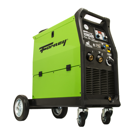
242 DUAL MIG WELDER
OPERATING MANUAL
FEATURES:
•
•
•
•
•
•
•
•
•
•
•
•
•
IDEAL FOR:
Steel, Stainless Steel, and Aluminum welding;
General Fabrication, Auto Body, Farm &
Ranch, Sheet Metal, Contractor, and More...
INCLUDES:
Torch with lead; Ground Cable and Clamp;
Input Power Cable; Gas Hose and Regulator;
Wheel Assembly Kit; Consumables Box
WWW.FORNEYIND.COM
240A Output
230V Input
Heavy-Duty torch
Aluminum drive system
Welds steel or aluminum with only the flip
of a switch
2 Euro connects; 1 dedicated to spool gun
Easy to use, increases productivity
Digital readout for true amps
Three trigger modes with spot weld timer
Optional spool gun increases versatility
Burn back and slope controls
Spray transfer capability
2 gas solenoids
ENGLISH
CAT# 327
REV 09/01/15
Advertisement
Chapters
Table of Contents

Subscribe to Our Youtube Channel
Related Manuals for Forney 242


Summary of Contents for Forney 242
- Page 1 242 DUAL MIG WELDER OPERATING MANUAL FEATURES: • 240A Output • 230V Input • Heavy-Duty torch • Aluminum drive system • Welds steel or aluminum with only the flip of a switch • 2 Euro connects; 1 dedicated to spool gun •...
- Page 2 WWW.FORNEYIND.COM...
- Page 3 STOP! PLEASE DO NOT RETURN TO THE STORE If you have questions or problems with your new welder, please call customer service at 1-800-521-6038 Monday through Friday from 7 a.m. - 5 p.m. (MST) or at www.forneyind.com/customer_service. Please take time to register your product at www.forneyind.com/customer_service/register_your_product/ Thank you, enjoy your new welder.
- Page 4 Above all, our employees will provide the same respect and caring attitude within the organization as they are expected to share with every Forney customer. Our goal will be to exceed our customers’ expectations through empowered people, guided by shared values and commitments.
-
Page 5: Warranty
Colorado, warrants to its original retail purchaser that the new Forney equipment sold after the effective date of this limited warranty is free of defects in material and workmanship at the time it is shipped by Forney. This is in lieu of all other warranties, expressed or implied. -
Page 6: Safety Information
BEFORE INSTALLING, OPERATING OR CARRYING OUT MAINTENANCE ON THE MACHINE, READ THE CONTENTS OF THIS MANUAL CAREFULLY, PAYING PARTICULAR ATTENTION TO THE SAFETY RULES AND HAZARDS. In the event of these instructions not being clear, please contact your Forney Authorized Dealer or Forney Customer Service 1-800-521-6038... -
Page 7: Personal Protection
Personal Protection Welding processes of any kind can be dangerous not only to the operator but to any person situated near the equipment, if safety and operating rules are not strictly observed. THE WELDING ARC PRODUCES VERY BRIGHT ULTRAVIOLET AND INFRARED LIGHT. -
Page 8: Fire Prevention
met als without seeking professional advice and inspection of the ventilation of the welding area. These metals produce extremely toxic fumes which can cause discomfort, illness and death. • Do not weld or cut in areas that are near chlorinated solvents. Vapors from chlori nated hydrocarbons, such as trichloroeth ylene and perchloroethylene, can be decomposed by the heat of an electric arc or its ultraviolet radiation. -
Page 9: High Frequency Radiation
• Protect flammable walls, ceilings, and floors with heat resistant covers or shields. • Check welding area to make sure it is free of sparks, glowing metal or slag, and flames before leaving the welding area. • Wear garments free of oil or other flammable substances such as leather gloves, thick cotton shirts with no synthetic materials, cuffless trousers, closed toed shoes. -
Page 10: Noise
• Do not alter power cord or power cord plug in any way. • Do not attempt to plug the welder into the power source if the ground prong on power cord plug is bent over, broken off, or missing. •... -
Page 11: Table Of Contents
Table of Contents WARRANTY ..............................4 SAFETY INFORMATION ..........................5 PRINCIPAL SAFETY STANDARDS ......................5 CALIFORNIA PROPOSITION 65 WARNING ....................5 EMF INFORMATION..........................5 PERSONAL PROTECTION ........................6 FIRE PREVENTION ..........................7 HIGH FREQUENCY RADIATION ......................8 ARC WELDING .............................8 ELECTRIC SHOCK ..........................8 NOISE ..............................9 ADDITIONAL SAFETY INFORMATION ....................9 TABLE OF CONTENTS ..........................10 INSTALLATION ............................11 LOCATION ............................11... -
Page 12: Installation
Installation Location Be sure to locate the welder according to the following guidelines: • In areas free from moisture and dust. • In areas with ambient temperature between 30° to 90°F. • In areas free from oil, steam and corrosive gases. •... -
Page 13: Assembly
Assembly Handle and Wheels Assembly (Fig. 1) • Unpack the welder. • Insert the axle (B) through the holes at the rear of the welder and slide a wheel (A) on to each end followed by the retaining washers (C). •... -
Page 14: Shielding Gas Guide
Shielding Gas Guide METAL NOTE Mild Steel Argon + CO2 Argon controls spatter Argon + CO2 + Oxygen Oxygen improves arc stability Aluminium Argon Arc stability, good fusion and minimum spatter. Higher heat input suitable for heavy sections. Argon + Helium Minimum porosity. -
Page 15: Replacing The Wire Liner
TIGHTEN NUT TO APPROPRIATE TIGHTNESS. EXCESSIVE PRESSURE STRAINS THE WIRE FEEDING MOTOR. TOO LITTLE PRESSURE DOES NOT ALLOW THE WIRE SPOOL TO STOP IMMEDIATELY. • Loosen and lower the plastic knob (A) (Fig.5). Release the upper roll (B) of the feeder. Extract the wire from the torch liner. -
Page 16: How To Choose The Wire Liner For Direct And Euro Connection Torches
In case you are replacing a Teflon or graphite wire liner, follow these instructions: • Install the new liner and insert the wire liner collet (3) and the O ring (4). • Mount the brass nut (1). • Cut the wire liner close to the brass nut. WARNING: THE LENGTH OF THE NEW WIRE LINER MUST BE THE SAME AS THE LINER YOU HAVE JUST PULLED OUT OF THE HOSE. -
Page 17: Setting The Wire Drive Tension
13. Line the wire up in the appropriate top groove of the drive roller, then push the drive tension arm against the drive roller. 14. Flip the quick release drive tensioner back into position on the drive tensioner arm. 15. Tighten (turn clockwise) the drive tension adjusting knob until the tension roller is applying enough force on the wire to prevent it from slipping out of the drive assembly. -
Page 18: Adjusting The Spool Position
seems to feed smoothly without slipping. 4. Close the wire drive cover on the spool gun. 5. When set correctly, there should be no slippage between the wire and the drive roller under normal conditions. Adjusting the Spool Position Before you begin welding, you may want to adjust the position of the spool so it is most comfortable for you. -
Page 19: Back Panel Operation
7. B.B.T. ( Burn Back Time) After releasing the torch trigger, wire will continue to feed for a short time. This function avoids burning of wire and consequent wire sticking to the contact tip. By turning the B.B.T. potentiometer clockwise with a screwdriver, the time during which wire will continue to feed after the trigger is released can be adjusted. -
Page 20: Technical Data Information Guide
Technical Data Information Guide Refer to the back of the welder for specifications. Welding Preparation • Connect the ground cable to the proper female outlet on the bottom right-hand corner of the welder (on some models the ground cable is already connected). Attach the ground clamp to the bare metal to be welded, making sure of good contact;... -
Page 21: Parts List
Parts List REF. # PART # ITEM DESCRIPTION 85005 DOOR LATCH 05000287 LEFT SIDE PANEL 85513 PLASTIC HINGE FOR DOOR 33705777 376C SMALL LEFT PANEL 33720311 9005 DIVIDING PANEL 04600275 SPOOL HOLDER 85130 FUSE HOLDER 85129 FUSE 44410081 METALLIC WIRE FEEDER 23005542 EURO BINZEL CONNECTION 21690675... - Page 22 REF. # PART # ITEM DESCRIPTION 22100009K DINSE SOCKET 85555 KNOB WITH CAP AND INDEX 85574 BLACK KNOB FOR SWITCH 77601051 YELLOW LABEL FOR ON-OFF SWITCH 40211532 SPOOL GUN TORCH WIRING ASSEMBLY 85530 SWITCH 22710084 MOTOR CONTROL PCB 33700427 9005 LOWER PANEL 44135176 CHOKE...
-
Page 23: Parts Diagram
Parts Diagram WWW.FORNEYIND.COM... -
Page 24: Mig Gun Torch Spare Parts List
MIG Gun Torch Spare Parts List NO. PART NUMBER ITEM DESCRIPTION QTY. NO. PART NUMBER ITEM DESCRIPTION QTY. 23005552 TWECO TORCH NOZZLE 22-62 TW2 62A-45 TORCH NECK 1 PC 05 23005528k PACK 02 23005525K INSULATOR 1PC PACK BLACK HANDLE FOR TW200 TORCH 0,9MM CONTACT TIP FOR TW2 14- 06 23005529K 03 23005526K... -
Page 25: Wiring Diagram
Wiring Diagram WWW.FORNEYIND.COM... -
Page 26: User Notes
User Notes _______________________________________________________________________________________ _______________________________________________________________________________________ _______________________________________________________________________________________ _______________________________________________________________________________________ _______________________________________________________________________________________ _______________________________________________________________________________________ _______________________________________________________________________________________ _______________________________________________________________________________________ _______________________________________________________________________________________ _______________________________________________________________________________________ _______________________________________________________________________________________ _______________________________________________________________________________________ _______________________________________________________________________________________ _______________________________________________________________________________________ _______________________________________________________________________________________ _______________________________________________________________________________________ _______________________________________________________________________________________ _______________________________________________________________________________________ _______________________________________________________________________________________ _______________________________________________________________________________________ _______________________________________________________________________________________ _______________________________________________________________________________________ _______________________________________________________________________________________ _______________________________________________________________________________________ _______________________________________________________________________________________ _______________________________________________________________________________________ _______________________________________________________________________________________ _______________________________________________________________________________________ _______________________________________________________________________________________ _______________________________________________________________________________________ _______________________________________________________________________________________ _______________________________________________________________________________________ _______________________________________________________________________________________ _______________________________________________________________________________________ _______________________________________________________________________________________ _______________________________________________________________________________________ _______________________________________________________________________________________ _______________________________________________________________________________________ _______________________________________________________________________________________ _______________________________________________________________________________________ _______________________________________________________________________________________... - Page 27 MANUEL D’UTILISATION DE LA SOUDEUSE MIG DOUBLE 242 CARACTÉRISTIQUES : • Sortie de 240 A • Entrée de 230 V • Chalumeau robuste • Système d’entraînement en aluminium • Soude l’acier ou l’aluminium à l’aide d’un simple interrupteur • 2 branchements Euro, 1 dédié au pistolet-bobine •...
- Page 28 ARRÊTEZ! NE RETOURNEZ PAS AU MAGASIN Si vous avez des questions ou des problèmes avec votre nouvelle soudeuse, veuillez appeler le service à la clientèle au +1 800 521-6038, du lundi au vendredi de 7 h à 17 h (HNR) ou rendez-vous sur www.forneyind.com/customer_service.
- Page 29 Surtout, nos employés feront preuve du même respect et de la même attitude attentive au sein de l’organisation et avec chaque client Forney. Notre objectif consiste à dépasser les attentes de nos clients grâce à des personnes capables, guidées par les mêmes valeurs et dévouement.
-
Page 30: Garantie
D) 90 jours : pièces de rechange. La main-d’œuvre n’est pas comprise. 4) La garantie limitée de Forney ne s’applique pas aux consommables comme les pièces de contact, les buses de coupage, les nettoyeurs de fil en feutre, les dévidoirs, les diffuseurs de gaz, les buses et les électrodes de chalumeau à plasma, les câbles de soudage ainsi que les buses et les pièces dont la dégradation est causée par l’usure normale. -
Page 31: Informations Concernant La Sécurité
DU PRÉSENT MANUEL, EN ACCORDANT UNE ATTENTION PARTICULIÈRE AUX RÈGLES DE SÉCURITÉ ET AUX RISQUES. Dans le cas où les instructions ne seraient pas claires, merci de contacter votre revendeur Forney autorisé ou le service à la clientèle Forney au +1 800 521-6038 Informations concernant la sécurité... -
Page 32: Protection Personnelle
À PROPOS DES STIMULATEURS CARDIAQUES ET DES PROTHÈSES AUDITIVES : Les personnes portant un stimulateur cardiaque ou des prothèses auditives doivent consulter leur médecin. Si vous obtenez l’accord de votre médecin, nous vous recommandons de suivre les procédures ci-dessus. Protection personnelle Les processus de soudage de toutes sortes peuvent être dangereux pour l’utilisateur, ainsi que pour toute personne à... -
Page 33: Prévention Des Incendies
• Évitez de souder, de couper ou de chauffer le plomb, le zinc, le cadmium, le mercure, le béryllium, l’antimoine, le cobalt, le manganèse, le sélénium, l’arsenic, le cuivre, l’argent, le baryum, le chrome, le vanadium, le nickel ou des métaux similaires sans consulter un professionnel et sans inspecter la ventilation de la zone de soudage. -
Page 34: Rayonnement À Haute Fréquence
Il doit préférablement être en béton ou en maçonnerie, ne doit pas être fait de tuiles, de moquette ou de tout autre matériau inflammable. • Protégez les murs, les plafonds et les planchers inflammables avec des protecteurs résistants à la chaleur. •... -
Page 35: Bruit
• Ne tentez pas de brancher la soudeuse dans une source d’alimentation si le contact de mise à la terre du cordon d’alimentation est plié, brisé ou manquant. • Ne laissez pas la soudeuse branchée à une source d’alimentation ou ne tentez pas de souder si la soudeuse, les câbles de soudage, le site de soudage ou le cordon d’alimentation de la soudeuse sont exposés à... - Page 36 Table des matières GARANTIE ..............................29 INFORMATIONS CONCERNANT LA SÉCURITÉ ....................30 NORMES DE SÉCURITÉ PRINCIPALES ....................30 PROPOSITION 65 DE L’ÉTAT DE LA CALIFORNIE ...................30 INFORMATION EMF..........................30 PROTECTION PERSONNELLE .......................31 PRÉVENTION DES INCENDIES ......................32 RAYONNEMENT À HAUTE FRÉQUENCE ....................33 SOUDAGE À L’ARC ..........................33 DÉCHARGE ÉLECTRIQUE ........................33 BRUIT ..............................34 INFORMATIONS SUPPLÉMENTAIRES CONCERNANT LA SÉCURITÉ...
-
Page 37: Installation
Installation Emplacement Assurez-vous d’installer la soudeuse en respectant les lignes directrices suivantes : • Dans un endroit sans humidité ni poussière. • Dans un endroit dont la température ambiante se situe entre 30 °F et 90 °F (1 °C et 32 °C). •... -
Page 38: Montage
Montage Montage de la poignée et des roues (Fig. 1) • Déballez la soudeuse. • Insérez l’essieu (B) dans les trous à l’arrière de la soudeuse et glissez une roue (A) dans chaque extrémité puis une rondelle de retenue (C). •... -
Page 39: Guide Du Gaz De Protection
Guide du gaz de protection MÉTAL REMARQUE Acier doux Argon + CO2 L’argon contrôle les éclaboussures. Argon + CO2 + Oxygène L’oxygène améliore la stabilité de l’arc. Aluminium Argon Stabilité de l’arc, bonne fusion et éclaboussure minimale. Une entrée de chaleur plus grande convient aux Argon + Hélium éléments lourds. - Page 40 APPLIQUEZ LA TENSION APPROPRIÉE À L’ÉCROU. UNE TENSION EXCESSIVE FATIGUERA LE MOTEUR D’ALIMENTATION DU FIL. UNE TENSION TROP FAIBLE NE PERMETTRA PAS À LA BOBINE DE FIL DE S’ARRÊTER IMMÉDIATEMENT. • Desserrez et abaissez le bouton de plastique (A) (Fig. 5). Relâchez la poulie supérieure (B) de l’alimentation.
-
Page 41: Remplacement Du Guide-Fil
Remplacement du guide-fil AVANT DE SUIVRE CETTE PROCÉDURE, ASSUREZ-VOUS QUE LA CONDUITE D’ALIMENTATION EN GAZ ET LE CÂBLE D’ALIMENTATION SONT DÉBRANCHÉS. • Débranchez le chalumeau de la machine. • Placez-le sur une surface plane et retirez soigneusement l’écrou en laiton (1). •... - Page 42 7. Ouvrez le boîtier de la bobine de fil, située à l’arrière du pistolet-bobine, en tournant le bouton de retenue dans le sens antihoraire. 8. Déroulez la bobine de fil et trouvez le bout du fil. 9. Après avoir vérifié que votre soudeuse est débranchée de l’alimentation en courant alternatif (c.a.), libérez le bout du fil de la bobine, mais sans le relâcher sinon le fil se déroulera tout seul.
-
Page 43: Réglage De La Tension De L'alimentation Du Fil
soudeuse en marche. Réglez l’interrupteur VOLTAGE (TENSION). Réglage de la tension de l’alimentation du fil AVERTISSEMENT : LES COUPS D’ARC PEUVENT BLESSER LES YEUX! POUR RÉDUIRE LES RISQUES DE COUPS D’ARC, ASSUREZ-VOUS QUE LE FIL SORTANT DE L’EMBOUT DU PISTOLET N’ENTRE PAS EN CONTACT AVEC LA MAUVAISE PIÈCE À SOUDER, LA PRISE DE MASSE OU TOUT MATÉRIEL MIS À... -
Page 44: Opération Du Panneau Avant
Opération du panneau avant 1. Interrupteur principal ON/OFF (MARCHE/ ARRÊT) (vert) : S’illumine lorsque vous mettez l’interrupteur de la soudeuse en position ON (MARCHE). 2. Bouton d’ajustement de la tension de soudage 3. Connexion du pistolet-bobine 4. Bouton d’ajustement de l’alimentation du fil Pour augmenter la vitesse du fil, tournez le potentiomètre dans le sens horaire;... -
Page 45: Opération Du Panneau Arrière
Opération du panneau arrière 1. Câble d’alimentation 2. Raccord de tuyau du gaz pour le chalumeau 1 (chalumeau MIG) 3. Raccord de tuyau du gaz pour le chalumeau 2 (pistolet-bobine) Guide d’information technique Consultez l’arrière de la soudeuse pour les spécifications. Préparation pour le soudage •... -
Page 46: Facteurs À Prendre En Considération Pour De Meilleurs Résultats De Soudure
Facteurs à prendre en considération pour de meilleurs résultats de soudure 1. Matériaux à souder (acier doux, acier inoxydable, aluminium). 2. Épaisseur des matériaux à souder. 3. Diamètre du fil de soudage. 4. Type de gaz de protection utilisé. À l’aide du bouton Mode, sélectionnez le mode de gâchette. •... -
Page 47: Liste Des Pièces
Liste des pièces RÉF. NUMÉRO DESCRIPTION DE L’ARTICLE QTÉ NUMÉRO DE PIÈCE 85005 LOQUET 05000287 PANNEAU DE GAUCHE 85513 CHARNIÈRE EN PLASTIQUE POUR LA PORTE 33705777 376C PETIT PANNEAU DE GAUCHE 33720311 9005 PANNEAU SÉPARATEUR 04600275 PORTE-BOBINES 85130 PORTE-FUSIBLES 85129 FUSIBLE 44410081 DÉVIDOIR MÉTALLIQUE... - Page 48 RÉF. NUMÉRO DESCRIPTION DE L’ARTICLE QTÉ NUMÉRO DE PIÈCE 85555 BOUTON AVEC COUVERCLE ET INDEX 85574 BOUTON NOIR POUR INTERRUPTEUR 77601051 ÉTIQUETTE JAUNE POUR INTERRUPTEUR DE MISE EN MARCHE ET ARRÊT 40211532 ENSEMBLE DE FILS POUR LE CHALUMEAU DU PISTOLET-BO- BINE 85530 INTERRUPTEUR...
-
Page 49: Schéma Des Pièces
Schéma des pièces WWW.FORNEYIND.COM... -
Page 50: Liste Des Pièces De Rechange Du Chalumeau Du Pistolet Mig
Liste des pièces de rechange du chalumeau du pistolet MIG RÉFÉRENCE DESCRIPTION DE L’ARTICLE QTÉ RÉFÉRENCE DESCRIPTION DE L’ARTICLE QTÉ 23005552 BUSE DE CHALUMEAU TWECO 22-62 COL DE CYGNE TW2 62A-45 PAQUET 05 23005528k DE 1 02 23005525K ISOLATEUR PAQUET DE 1 POIGNÉE NOIRE POUR CHALUMEAU POINT DE CONTACT DE 0,9 MM 06 23005529K... -
Page 51: Schéma De Câblage
Schéma de câblage POSITION NOIR ROUGE VIOLET BLANC ORANGE GRIS GRIS GRIS NOIR ROUGE GRIS ROUGE NOIR BLEU ROUGE MAX. BLANC BLANC ROUGE NOIR WWW.FORNEYIND.COM... -
Page 52: Remarques Pour L'utilisateur
Remarques pour l’utilisateur _______________________________________________________________________________________ _______________________________________________________________________________________ _______________________________________________________________________________________ _______________________________________________________________________________________ _______________________________________________________________________________________ _______________________________________________________________________________________ _______________________________________________________________________________________ _______________________________________________________________________________________ _______________________________________________________________________________________ _______________________________________________________________________________________ _______________________________________________________________________________________ _______________________________________________________________________________________ _______________________________________________________________________________________ _______________________________________________________________________________________ _______________________________________________________________________________________ _______________________________________________________________________________________ _______________________________________________________________________________________ _______________________________________________________________________________________ _______________________________________________________________________________________ _______________________________________________________________________________________ _______________________________________________________________________________________ _______________________________________________________________________________________ _______________________________________________________________________________________ _______________________________________________________________________________________ _______________________________________________________________________________________ _______________________________________________________________________________________ _______________________________________________________________________________________ _______________________________________________________________________________________ _______________________________________________________________________________________ _______________________________________________________________________________________ _______________________________________________________________________________________ _______________________________________________________________________________________ _______________________________________________________________________________________ _______________________________________________________________________________________ _______________________________________________________________________________________ _______________________________________________________________________________________ _______________________________________________________________________________________ _______________________________________________________________________________________ _______________________________________________________________________________________ _______________________________________________________________________________________... - Page 53 MANUAL DE INSTRUCCIONES DE LA SOLDADORA DUAL MIG 242 CARACTERÍSTICAS: • Salida de 240 A • Entrada de 230 V • Antorcha de alto rendimiento • Sistema impulsor de aluminio • Suelda acero y aluminio con solo presionar un interruptor •...
- Page 54 ¡DETÉNGASE! NO LA DEVUELVA A LA TIENDA Si tiene preguntas o problemas con su nueva soldadora, comuníquese con atención al cliente al +1-800-521-6038, de lunes a viernes de 7.00 a 17.00, hora estándar de la montaña (MST) o ingrese a www.forneyind.com/customer_service. Tómese un momento para registrar su producto en www.forneyind.com/customer_service/register_your_product/ Gracias y disfrute de su nueva soldadora.
- Page 55 Sobre todo, nuestros empleados brindarán la misma actitud respetuosa y atenta dentro de la organización y se espera que la compartan con cada cliente de Forney. Nuestra meta es superar las expectativas de nuestros clientes a través de personas capacitadas, guiadas por valores y compromisos compartidos.
-
Page 56: Garantía
Forney. Esta reemplaza a cualquier otra garantía, ya sea explícita o implícita. -
Page 57: Información De Seguridad
ANTES DE INSTALAR, UTILIZAR O REALIZAR EL MANTENIMIENTO EN LA MÁQUINA, LEA EL CONTENIDO DE ESTE MANUAL DETENIDAMENTE, PRESTANDO ESPECIAL ATENCIÓN A LAS REGLAS DE SEGURIDAD Y PELIGROS. En el caso de que estas instrucciones no le resulten claras, comuníquese con su vendedor de Forney autorizado o con Atención al cliente de Forney al +1-800-521-6038 Información de seguridad... -
Page 58: Protección Personal
Protección personal Los procesos de soldado de cualquier tipo pueden ser peligrosos no solo para el operador sino también para las personas ubicadas cerca del equipo si no se cumplen con las reglas de operación y seguridad de manera estricta. EL ARCO DE SOLDADURA PRODUCE LUZ ULTRAVIOLETA E INFRARROJA MUY BRILLANTE. -
Page 59: Prevención De Incendios
• No suelde ni corte en áreas cercanas a solventes clorados. Los vapores de hidrocarburos clorados, como el tricloroetileno y percloroetileno, se pueden descomponer por acción del calor de un arco eléctrico o su radiación ultravioleta. Estas acciones pueden causar fosgeno, un gas altamente tóxico, además de otros gases que irritan los pulmones y los ojos. -
Page 60: Radiación De Alta Frecuencia
• Use prendas sin derivados del petróleo u otras sustancias inflamables, como guantes de cuero, camisas gruesas de algodón sin materiales sintéticos, pantalones sin dobladillo, calzado cerrado. Mantenga el cabello largo recogido hacia atrás. • Quite los materiales combustibles como encendedores y fósforos antes de soldar. •... -
Page 61: Ruido
• No permita que la soldadora esté conectada a la fuente de energía ni intente soldar si la soldadora, los cables de soldar, el sitio para soldar o el cable eléctrico de la soldadora están expuestos a cualquier forma de precipitación atmosférica, o si están rociados con agua salada. •... -
Page 62: Índice
Índice GARANTÍA ...............................55 INFORMACIÓN DE SEGURIDAD ........................56 NORMAS DE SEGURIDAD PRINCIPALES ....................56 ADVERTENCIA DE LA PROPOSICIÓN 65 DE CALIFORNIA ..............56 INFORMACIÓN SOBRE EMF (CAMPOS ELECTROMAGNÉTICOS) ............56 PROTECCIÓN PERSONAL ........................57 PREVENCIÓN DE INCENDIOS ......................58 RADIACIÓN DE ALTA FRECUENCIA .....................59 SOLDADURA POR ARCO ........................59 DESCARGA ELÉCTRICA ........................59 RUIDO ..............................60 INFORMACIÓN DE SEGURIDAD ADICIONAL ..................60... -
Page 63: Instalación
Instalación Ubicación Asegúrese de ubicar la soldadora de acuerdo con las siguientes pautas: • En áreas libres de humedad y polvo. • En áreas con temperatura ambiente entre 30 y 90 °F (-1 a 32 °C). • En áreas libres de aceite, vapor y gases corrosivos. •... -
Page 64: Ensamblaje
Ensamblaje Ensamblaje del asa y las ruedas (Fig. 1) • Desempaque la soldadora. • Inserte el eje (B) a través de los orificios que se encuentran en la parte trasera de la soldadora y deslice una rueda (A) en cada extremo seguida por las arandelas de sujeción (C). -
Page 65: Guía De Gases De Protección
Guía de gases de protección METAL NOTA Acero suave Argón + CO2 El argón controla las salpicaduras. Argón + CO2 + Oxígeno El oxígeno mejora la estabilidad del arco. Aluminio Argón Estabilidad del arco, buena fusión y salpicaduras mínimas. Argón + Helio Entrada de mayor calor apropiada para secciones gruesas. -
Page 66: Reemplazo Del Revestimiento De Alambre
AJUSTE LA TUERCA HASTA DONDE SEA APROPIADO. LA PRESIÓN EXCESIVA FUERZA AL MOTOR DE ALIMENTACIÓN DE ALAMBRE. CUANDO LA PRESIÓN ES MUY POCA, NO PERMITE QUE LA BOBINA DE ALAMBRE SE DETENGA INMEDIATAMENTE. • Afloje y baje la perilla de plástico (A) (Fig. 5). Suelte el rodillo superior (B) del alimentador. Extraiga el alambre del revestimiento de la antorcha. -
Page 67: Cómo Elegir El Revestimiento De Alambre Para Antorchas Con Conexión Directa Y Europea
En caso de reemplazar un revestimiento de alambre de teflón o grafito, siga estas instrucciones: • Instale el nuevo revestimiento e inserte el anillo metálico del revestimiento de alambre (3) y la junta tórica (4). • Coloque la tuerca de bronce (1). •... -
Page 68: Ajuste De La Tensión Impulsora Del Alambre
13. Alinee el alambre en la ranura superior correspondiente del rodillo impulsor, luego empuje el brazo de tensión impulsora contra el rodillo impulsor. 14. Voltee el tensor impulsor de liberación rápida a su posición en el brazo tensor impulsor. 15. Ajuste (gire en el sentido de las agujas del reloj) la tensión impulsora ajustando la perilla hasta que el rodillo de tensión aplique suficiente fuerza en el alambre para evitar que se salga del ensamblaje impulsor. -
Page 69: Ajuste De La Posición De La Bobina
4. Cierre la cubierta del impulsor de alambre en la pistola de bobina. 5. Cuando se fija de manera correcta, no debe haber deslizamientos entre el alambre y el rodillo impulsor en condiciones normales. Ajuste de la posición de la bobina Antes de comenzar a soldar, es preferible ajustar la posición de la bobina de modo que quede en una posición cómoda para usted. -
Page 70: Funcionamiento Del Panel Posterior
B.B.T. ( tiempo de retroceso de alambre) Después de soltar el gatillo de la antorcha, el alambre continuará alimentándose por poco tiempo. Esta función evita que el alambre se queme y que, en consecuencia, se pegue a la pieza de contacto. Al girar el potenciómetro de B.B.T. -
Page 71: Guía Informativa De La Hoja De Datos
Guía informativa de la hoja de datos Consulte las especificaciones en la parte posterior de la soldadora. Preparación de la soldadura • Conecte el cable a tierra con el toma hembra correspondiente en la esquina inferior derecha de la soldadora (en algunos modelos el cable con conexión a tierra ya viene conectado). Coloque la abrazadera de descarga a tierra en el metal desnudo a soldar, asegurándose de que haga buen contacto. -
Page 72: Lista De Piezas
Lista de piezas N.° DE REF. N.° DE PIEZA DESCRIPCIÓN DEL ARTÍCULO CANT. 85005 PESTILLO DE LA PUERTA 05000287 PANEL LATERAL IZQUIERDO CON SERIGRAFIA 85513 BISAGRA DE PLµSTICO 40X40MM 33705777 376C PEQUENO PANEL LATERAL IZQUIERDO 33720311 9005 PANEL INTERIOR 04600275 ASPO COMPLETO PARA BOBINAS D.50 85130 PORTAFUSIBLE... - Page 73 N.° DE REF. N.° DE PIEZA DESCRIPCIÓN DEL ARTÍCULO CANT. 22100009K TOMA TIPO DINSE 50MM2 TBE35-50 85555 PERILLA+INDICE 85574 POMO PARA CONMUTADOR NEGRO 77601051 ETIQUETA AMARILLA ON/OFF 40211532 CONEXION TORCHA SPOOL-GUN CON.7 POLOS 85530 INTERRUPTOR 25 A 10POS 1PH 22710084 FICHA CONTROLO 33700427 9005 PANEL INFERIOR...
-
Page 74: Diagrama De Piezas
Diagrama de piezas WWW.FORNEYIND.COM... -
Page 75: Lista De Repuestos De Antorcha Con Pistola Mig
Lista de repuestos de antorcha con pistola MIG NÚMERO DE NÚMERO DE Nro. DESCRIPCIÓN DEL ARTÍCULO CANT. Nro. DESCRIPCIÓN DEL ARTÍCULO CANT. PIEZA PIEZA BOQUILLA DE ANTORCHA TWECO CUELLO DE ANTORCHA TW2 62A- 23005552 23005528k 22-62 45 PAQUETE DE 1 PIEZA 23005525K AISLANTE PAQUETE DE 1 PIEZA MANGO NEGRO PARA ANTORCHA... -
Page 76: Diagrama De Cableado
Diagrama de cableado POSICIÓN NEGRO ROJO VOILETA BLANCO NARANJA GRIS GRIS GRIS NEGRO ROJO GRIS ROJO NEGRO AZUL ROJO MÁX. BLANCO BLANCO ROJO NEGRO WWW.FORNEYIND.COM... -
Page 77: Notas Del Usuario
Notas del usuario ______________________________________________________________________________________ ______________________________________________________________________________________ ______________________________________________________________________________________ ______________________________________________________________________________________ ______________________________________________________________________________________ ______________________________________________________________________________________ ______________________________________________________________________________________ ______________________________________________________________________________________ ______________________________________________________________________________________ ______________________________________________________________________________________ ______________________________________________________________________________________ ______________________________________________________________________________________ ______________________________________________________________________________________ ______________________________________________________________________________________ ______________________________________________________________________________________ ______________________________________________________________________________________ ______________________________________________________________________________________ ______________________________________________________________________________________ ______________________________________________________________________________________ ______________________________________________________________________________________ ______________________________________________________________________________________ ______________________________________________________________________________________ ______________________________________________________________________________________ ______________________________________________________________________________________ ______________________________________________________________________________________ ______________________________________________________________________________________ ______________________________________________________________________________________ ______________________________________________________________________________________ ______________________________________________________________________________________ ______________________________________________________________________________________ ______________________________________________________________________________________ ______________________________________________________________________________________ ______________________________________________________________________________________ ______________________________________________________________________________________ ______________________________________________________________________________________ ______________________________________________________________________________________ ______________________________________________________________________________________ ______________________________________________________________________________________ ______________________________________________________________________________________ ______________________________________________________________________________________... - Page 78 WWW.FORNEYIND.COM...
- Page 79 WWW.FORNEYIND.COM...
- Page 80 WWW.FORNEYIND.COM...
- Page 81 Forney Industries, Inc. 2057 Vermont Drive Fort Collins, CO 80525 +1-800-521-6038 www.forneyind.com WWW.FORNEYIND.COM...
Need help?
Do you have a question about the 242 and is the answer not in the manual?
Questions and answers