
Related Manuals for Haug EN SL SLC MT


Summary of Contents for Haug EN SL SLC MT
- Page 1 Operating instructions Discharging power pack EN SL SLC MT Ident number: 01.7909.055 (100 V), 01.7909.005 (115 V), 01.7908.005 (230 V) Keep for future use! Static Line...
-
Page 3: Table Of Contents
Table of contents Operator instructions ..........4 Symbols used in operating instructions ......4 Symbols on the discharging power pack ......5 Safety ................6 Intended use ..............7 Product overview............8 Install ................9 Operate ..............13 Normal operation ............13 Cyclic operation .............. 13 Troubleshooting ............ -
Page 4: Operator Instructions
Operator instructions 1 Operator instructions Before installation and commissioning read these operating instruction in full. Always observe the safety instructions. These operating instruction is a part of the product; make sure you retain them for later use or subsequent owners. The discharging power pack is maintenance free and operationally safe when used as intended. -
Page 5: Symbols On The Discharging Power Pack
Operator instructions Never dispose of with household garbage. Caution, danger spot warning! 1.2 Symbols on the discharging power pack WARNING! High voltage ATTENTION! Only plug in/unplug the ionizing unit at the HV terminal when the discharging power pack is switched off. -
Page 6: Safety
Safety 2 Safety Only the persons authorized by the operator may carry out tasks on the discharging power pack. The installer must be a trained and qualified electrician and read the operating instructions in full. The operator must read the operating instructions in full. When working on the discharging power pack, switch off the voltage supply and secure against inadvertent switching on. -
Page 7: Intended Use
In combination with an ionizing unit, electrostatic charges are neutralized in a production process. Always observe the installation and operating conditions indicated in these operating instructions. Warranty only covers products, accessories or spare parts of HAUG GmbH & Co. KG. -
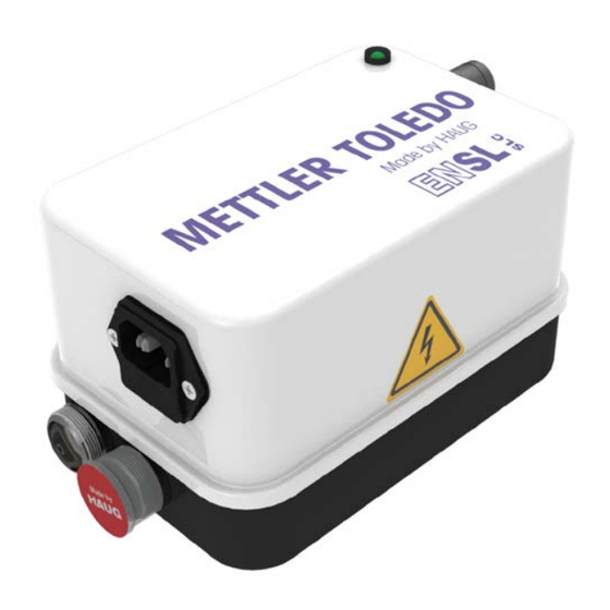
Page 8: Product Overview
Product overview 3 Product overview A Power switch (is lit green if the discharging power pack is switched on) B Signal socket C Earth connection point (terminal) D Jumper plug E Indicator light F 2 x HV connection G Fuse holder with fuse (Replacing fuse, refer page H ICE power connection... -
Page 9: Install
• Never install at a location subject to direct solar irradiation. 1. Check the model plate of the discharging power pack against the ordering data. In the event of damage to the discharging power pack, contact HAUG GmbH & Co. KG. 2. Before connecting, make sure that the correct supply voltage is available for the discharging power pack. - Page 10 Install 3. Place the discharging power pack at the desired place of use. • The position of the discharging power pack has does not affect its function. • Make sure that the discharging power pack is switched off. 4. The ground socket of the discharging power pack must be connected to ground potential in line with...
- Page 11 Install Contact and separation spark-overs! When the ionizing unit is plugged in or unplugged while the discharging power pack is switched on, spark-overs will occur at the HV connection. This may result in defects in the discharging power pack. • Switch off discharging power pack before plugging in/unplugging ionizing unit.
- Page 12 Install 7. If necessary, connect the signal line to the signal socket. • The discharging power pack can be cycled via the signal socket. Configuration of the signal socket: A External control voltage B External clock switch Pin 1 External control voltage (square wave signal, 1 kHz, 10 V, positive)
-
Page 13: Operate
Operate 5 Operate Preconditions: The discharging power pack and the ionizing unit are connected and installed as specified in the operator instructions. 5.1 Normal operation There is no signal line connected to the signal socket. The jumper plug must be connected to the signalling socket. 1. -
Page 14: Troubleshooting
• Faults may only be eliminated by a trained and qualified electrician. NOTE: If the error cannot be removed in this way, return the discharging power pack and ionizing unit for checking to HAUG GmbH & Co. KG (the address is provided on the back of the envelope). Fault Cause... -
Page 15: Replacing Fuse
Troubleshooting 6.1 Replacing fuse Damage to equipment! An incorrect fuse in the discharging power pack may cause a defect. This may result in a cable fire. • Only use fuses of the specified type. • Never use repaired fuses. • Never bridge the fuse. The unit type and the rated voltage are indicated on the nameplate. -
Page 16: Flow Chart
Troubleshooting 6.2 Flow chart The indicator lamp does not illuminate. Switch off discharging power pack and unplug ionizing units. Disconnect signalling line from discharging power pack and screw jumper plug onto the signalling socket. Switch on the discharging power pack. Discharging power Indicator lamp stays off? pack is faulty... -
Page 17: Accessories/Spare Parts
Accessories/spare parts 7 Accessories/spare parts The supplier of accessories and spare parts is the authorized local sales agent of Mettler-Toledo. Article Order number Point electrode 11107765 Optional second electrode 11107762 U-Electrode universal 11107764 U-Electrode small 11140161 Ionizing kit Quantos System 11141829 Mains cable (country-specific) On request... -
Page 18: Technical Data
Technical data 8 Technical data 8.1 Characteristics and specification Reference temperature 23 °C HV terminals High-voltage 6.7 ±1 kV~ ≤ 5 mA Short-circuit current Cannot be used in pulsed mode 8.2 Supply voltage Frequency Power Unit type Rated value range consumption 01.7909.055 100 V~ ±10 %... -
Page 19: Ambient Conditions
Technical data 8.3 Ambient conditions Never use in areas with potentially explosive atmospheres. Must only be used indoors. Height above mean seal level to 2000 m Temperature: Rated application range +5 to +45°C Limit range for storage and -15 to +60°C transport Relative humidity: Rated application range... -
Page 20: Housing
Technical data 8.4 Housing Protection type IP 20 Protection class Overvoltage category Pollution severity Mains connection About IEC power cord Dimensions: Height 170 mm Width 110 mm Depth 100 mm Weight: 3.5 kg... -
Page 21: Taking Out Of Operation
Taking out of operation 9 Taking out of operation Electric shock hazard! The discharging power pack is operated electrically and generates a high electric voltage. Improper decommissioning may result in electric shock. • Decommissioning may only be carried out by a trained and qualified electrician. - Page 24 made by...
Need help?
Do you have a question about the EN SL SLC MT and is the answer not in the manual?
Questions and answers