Table of Contents
Advertisement
Advertisement
Table of Contents

Related Manuals for Haug EN SL LC


Summary of Contents for Haug EN SL LC
- Page 1 Power Pack EN SL / EN SL LC / EN SL RLC Keep for future use!
-
Page 3: Table Of Contents
Table of contents Operator instructions................ 5 Safety ....................6 Intended use..................8 Description of unit................9 Installation ..................10 Application..................14 Troubleshooting ................15 Replacing fuse .................... 16 Flow chart....................17 Accessories ..................18 Technical data ................. 20 Characteristics and specification..............20 Supply voltage .................... - Page 4 01.7780.200, 01.7780.208, 01.7780.220, 01.7781.200, 01.7781.208, 01.7781.220 EN SL with thermal cutout: 01.7830.000, 01.7831.000 EN SL LC with thermal cutout and signalling lamp: 01.7833.000, 01.7833.050, 01.7834.000, 01.7834.050 EN SL RLC with thermal cutout, signalling lamp and signalling socket: 01.7835.100, 01.7835.150, 01.7836.100, 01.7836.150...
-
Page 5: Operator Instructions
Operator instructions The following signal words are 1 Operator used: instructions WARNING! These operator instructions must be read completely before installation and If ignored commissioning of the power pack. severe personal injury. They form a part of the power pack ... -
Page 6: Safety
Safety 2 Safety WARNING! Risk of electric shock. All activities must be performed only High electric voltage in power pack. by persons authorized by the owner. Risk of electric shock when touching Such persons must live parts within power pack. ... - Page 7 Safety ATTENTION! Risk of short circuit. Spark-overs and leakage paths at the high-voltage terminals can occur as a result of moisture and wetness. Short circuits within the power pack are the likely consequence. Protect the power pack from wetness and moisture. ...
-
Page 8: Intended Use
HAUG ionizing units with X - 2000 connector. Only HAUG ionizing units with X - 2000 connectors must be connected with the power pack and operated. The warranty only covers units and accessories of HAUG GmbH &... -
Page 9: Description Of Unit
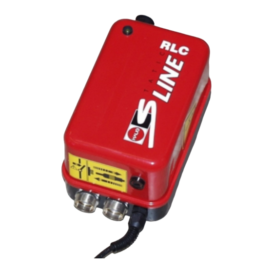
Description of unit 4 Description of unit Mains switch Green light in switch illuminates when power pack is on. Signalling socket (RLC types only) Ground connection (terminal) Signalling lamp (LC and RLC types only) Bracket High-voltage terminals Mains supply Fuse holder with fuse (for replacement, refer to page 16, Chapter 7.1). -
Page 10: Installation
Check the model plate of the power pack against the ordering data. In the event of damage to the power pack, contact HAUG GmbH & Co. KG. Before connecting, check to ensure that the power pack is suitable for the local mains voltage. - Page 11 Installation Ensure that the power pack is switched off. Connect the ground socket of the power pack with the machine ground connection. Connect the power pack to the mains. Connect the PE conductor (green-yellow) with the protective earth of the mains. ...
- Page 12 Installation ATTENTION! Risk of overheating. If the maximum permissible connected length is exceeded, the power pack will overheat during operation. This may result in damage to power packs not equipped with thermal cutout and cause a fault. The maximum permissible connected length must not be exceeded.
- Page 13 Installation RLC types only If required – if an error message needs to be evaluated, connect the signalling line to the signalling socket. Configuration of the signalling socket. Pin 1: Switching contact Pin 2: Joint connection relay Pin 3: NC contact Pin 4: Not assigned Pin 5: Not assigned Pin 6: Not assigned...
-
Page 14: Application
Application 6 Application Preconditions: The power pack and the ionizing unit must be connected and installed as specified in the operator instructions. Switch on the power pack using the mains switch. The mains switch will illuminate to confirm. The power pack is in operating mode. -
Page 15: Troubleshooting
Troubleshooting 7 Troubleshooting NOTE: If the error cannot be removed in this way, return the power pack and ionizing unit for checking to HAUG GmbH & Co. KG (for address, see reverse). Error Cause Measure for elimination No ionization Mains failure Check mains fuse. -
Page 16: Replacing Fuse
Shut the power pack damaged. down immediately and secure against switching Signalling lamp flashing The ionizing unit is faulty. Follow work sequence (EN SL LC and EN SL RLC according to the flow chart only) below. 7.1 Replacing fuse ATTENTION! Risk of faults! An incorrect fuse in the power pack may cause a fault. -
Page 17: Flow Chart
Troubleshooting 7.2 Flow chart Indicator lamp flashes ( LC/RLC ) or relay contact ( RLC ) switches to fault. Switch off power pack and unplug ionizing units. Allow power pack to cool down for 15 minutes and then switch on. Signalling lamp Power pack is faulty flashing? -
Page 18: Accessories
Accessories 8 Accessories Order Article Illustrations number Signal plug X – 7807 5 m shielded signalling line K6 with 06.8976.000 assembled plug 10 m shielded signalling line K6 with 06.8976.001 assembled plug 20 m shielded signalling line K6 with 06.8976.002 assembled plug... - Page 19 Accessories Order Article Illustrations number Bracket for power 10.0023.000 pack Blind plug for HV X – 1080 terminals Combicheck 12.7231.000...
-
Page 20: Technical Data
9 Technical data 9.1 Characteristics and specification Reference temperature 23 °C High-voltage terminals 2 HAUG- High-voltage terminals All HAUG ionizing units fitted with Connectable HAUG ionizing units X - 2000 connector High-voltage U = approx. 7 - 8 kVAC Contact load max. 24 VAC/35 VDC, Signalling terminal EN SL RLC max. -
Page 21: Supply Voltage
Technical data 9.2 Supply voltage Nominal Operating Frequency Unit type Power input value range range 01.7781.208, 01.7834.050, 100 VAC ±10 % 50 - 60 Hz = 40 VA 01.7836.150 01.7781.220 115 VAC ±10 % 50 - 60 Hz = 20 VA 01.7781.200, 01.7831.000, 115 VAC... -
Page 22: Ambient Conditions
Technical data 9.3 Ambient conditions Do not use in areas with potentially explosive atmospheres. Only for inside use. Temperature: Rated application range +5 °C to +45 °C Extreme range for storage and transport -15 °C to +60 °C Humidity: Rated application range 20 % to 65 % RF Extreme range for storage and transport 0 % to 85 % RF... -
Page 23: Connected Lengths
Technical data 9.4 Connected lengths Permissible Maximum ionizing Maximum ionizing Power Pack connected length bar length Type A bar length Type B 01.7780.220, 4.7 m 1.4 m 01.7781.220 01.7780.200, 01.7780.208, 01.7781.200, 01.7781.208, 01.7830.000, 01.7831.000, 01.7833.000, 10 m 01.7833.050, 01.7834.000, 01.7834.050, 01.7835.100, 01.7835.150, 01.7836.100,... -
Page 24: Housing
Technical data 9.5 Housing Protection type IP 54 Protection class Mains supply approx. 2,6 m fixed on unit Dimensions: Height approx. 170 mm Width approx. 110 mm Depth approx. 100 mm Weight: approx. 3.5 kg... -
Page 25: Decommissioning
Decommissioning 10 Decommissioning Switch off the machine and secure against unintended switching on. Switch off power pack and secure against inadvertent operation. Disconnect the ionizing unit from the power pack. Disconnect the power pack from the mains and remove. -
Page 26: Disposal
Disposal 11 Disposal Observe and maintain national and regional waste disposal regulations for the disposal of the power pack.
Need help?
Do you have a question about the EN SL LC and is the answer not in the manual?
Questions and answers