Advertisement
Quick Links
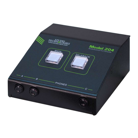
Model 204 Announcer's Console
User Guide
Issue 3, August 2020
This User Guide is applicable for serial numbers
M204-00501 and later with application firmware 1.4 and later
and STcontroller application version 2.04.00 and later.
Copyright © 2020 by Studio Technologies, Inc., all rights reserved
www.studio-tech.com
50639-0820, Issue 3
Advertisement

Related Manuals for Studio Technologies 204


Summary of Contents for Studio Technologies 204
- Page 1 Issue 3, August 2020 This User Guide is applicable for serial numbers M204-00501 and later with application firmware 1.4 and later and STcontroller application version 2.04.00 and later. Copyright © 2020 by Studio Technologies, Inc., all rights reserved www.studio-tech.com 50639-0820, Issue 3...
- Page 2 This page intentionally left blank.
-
Page 3: Table Of Contents
Revision History ............4 Introduction ..............5 Getting Started ............. 10 Operation ..............19 Technical Notes ............24 Specifications ............... 28 Appendix A: Model 204 Block Diagram ......29 Model 204 User Guide Issue 3, August 2020 Studio Technologies, Inc. Page 3... -
Page 4: Revision History
M204-00501 and later.) Issue 2, October 2018: • Documents addition of the Push to Mute/Tap to Latch main button operating mode. Issue 1, May 2018: • Initial release. Issue 3, August 2020 Model 204 User Guide Page 4 Studio Technologies, Inc. -
Page 5: Introduction
Applications eSports, live event, entertainment, and streaming broadcast applications. The unit is The Model 204 on its own can provide an housed in a compact, rugged steel enclosure “all-Dante” solution for one on-air talent that’s intended for table-top use. Calling the location. - Page 6 Set up, configuration, and operation of the ronments easy to accomplish. The talkback Model 204 is simple. An etherCON® RJ45 audio channel is available as a Dante out- jack is used to interconnect with a standard...
- Page 7 Ethernet Data and PoE AES67 interoperability standard. In this mode the two transmitter (output) channels The Model 204 connects to a local area net- will function in multicast; unicast is not sup- work (LAN) by way of a standard 100 Mb/s ported.
- Page 8 Configuration Flexibility will emulate a user pressing its associated The Model 204 can be configured to meet pushbutton switch. Remote Control Input 1 the needs of specific applications and user can also be configured to provide a Main Out preferences.
- Page 9 Model headphone output. This stereo pair enters 204 by way of Dante inputs 1 and 2 and the unit by way of Dante inputs 3 and 4. is routed in stereo to the left and right channels of the headphone output.
-
Page 10: Getting Started
3-pin female Firmware Updating XLR connector. Special applications may The Model 204 was designed so that its ca- utilize the two remote control inputs that pabilities and performance can be enhanced are accessible using a 3.5 mm 3-conductor in the future. - Page 11 Microphone Input muff”) broadcast-style headsets can be directly connected using a 3-conductor The Model 204 provides a 3-pin female XLR ¼-inch plug. Following the usual convention connector that allows a balanced dynamic or the left channel should be terminated on the...
- Page 12 A 3.5 mm microphone output circuitry. 3-conductor jack is located on the Model 204’s back panel and provides access to The microphone output can be connected the two remote control inputs. The input to balanced (differential) analog micro- circuitry is “active low,”...
- Page 13 These can cific application. either be unicast, multicast, or a combina- tion of the two. If the Model 204’s transmitter Model 204 Configuration channels need to be routed to more than The STcontroller software application is two flows it’s possible that an intermediary...
- Page 14 35, 43, 52, and 59 dB. The compressor active LED, orange in color Installing STcontroller and visible on the back of the Model 204’s STcontroller is available free of charge on enclosure adjacent to the microphone input the Studio Technologies’ website (www.
- Page 15 B adjusts its level. A stereo pair can enter tions it’s typical to want the user to have a the Model 204 by way of Dante input chan- single potentiometer to simultaneously adjust nels 3 and 4. These signals, whose level is...
- Page 16 Its level will be adjusted using pot signal to fully mute. Selecting the full mute B. A stereo pair can enter the Model 204 by mode may be appropriate for applications way of Dante input channels 3 and 4. These where minimizing the chance of audio “leak-...
- Page 17 Upon Model 204 power up • Push to Mute: If this mode is selected the main button will be in its inactive state the main button function will normally be and its red LED will be lit.
- Page 18 The system mode configures the overall will mute on both the Dante main output manner in which the Model 204 operates. channel and the microphone output con- Specifically, it determines how the Dante nector and the button’s LED will change...
-
Page 19: Operation
Initial Operation the amount of ambient light present in the Model 204’s location. The choices are low The Model 204 will start to function as soon and high. as a Power-over-Ethernet (PoE) power source is connected. However, it may take... - Page 20 Functions within the Dante Controller and slowly flash green when this specific Model STcontroller software applications allow a 204 is part of a Dante network and is serv- specific Model 204 unit to be identified. Each ing as the clock master. It’s possible that application provides an “eyeball”...
- Page 21 • Latching: If this mode is selected the microphone output connector that’s located audio signal associated with the Dante on the back panel of the Model 204. How main output channel and the microphone the button functions will depend on the...
- Page 22 Latching modes. Whenever the main Remote Control Inputs button is momentarily “tapped” its status The Model 204 allows two switches or con- will alternate between active and muted. tact closures to be connected to the remote When the main button’s function is ac- control inputs.
- Page 23 The three rotary potentiometers (pots), lo- ton will be forced to be inactive whenever cated on the Model 204’s front panel, allow the talkback function is active. The on- level adjustment of the Dante audio input...
-
Page 24: Technical Notes
In the unfortunate event that a specific Mod- ing the link-local protocol. This protocol is el 204’s IP address is “lost,” the Address known in the Microsoft® world as Automatic Resolution Protocol (ARP) networking com- Private IP Addressing (APIPA). - Page 25 There are even specialized switches that firmware version to be identified. Connect are optimized for entertainment-associated the Model 204 unit to the network and let applications. Refer to the Audinate website it connect and start to function. Then, after (www.audinate.com) for details on optimizing starting STcontroller, review the list of identi- networks for Dante applications.
- Page 26 “boot loader” program that will au- the naming convention required by the Model tomatically load the new application firm- 204, the name of the zip file itself will include ware file (m204.bin). During this time the file’s version number. For example, a file period an LED, located adjacent to the named m204v1r4MCU.zip would indicate...
- Page 27 A command in the STcontroller software the unit’s existing application firmware will application allows the Model 204’s defaults begin. to be reset to the factory values. From STcontroller select the Model 204 for Ultimo Firmware Update which you want to restore its defaults.
-
Page 28: Specifications
Remote Control Inputs: 3-conductor 3.5 mm jack of gain Ethernet: Neutrik etherCON RJ45 Dynamic Range: 98 dB, A-weighted USB: type A receptacle (located inside Model 204’s Phantom Power: P48 per IEC 61938 standard, on/off enclosure and used only for updating firmware) selectable with status LED Configuration: requires Studio Technologies’... -
Page 29: Appendix A: Model 204 Block Diagram
MODEL 204 ANNOUNCER’S CONSOLE Appendix A: Model 204 Block Diagram The following block diagram shows a simplified version of the Model 204’s microphone input and microphone output circuitry. Model 204 User Guide Issue 3, August 2020 Studio Technologies, Inc. Page 29...
Need help?
Do you have a question about the 204 and is the answer not in the manual?
Questions and answers