Bionet BM3 Service Manual
Patient monito
Hide thumbs
Also See for BM3:
- User manual (235 pages) ,
- Operation manual (226 pages) ,
- User manual (170 pages)
Table of Contents
Advertisement
Advertisement
Table of Contents

Related Manuals for Bionet BM3


Summary of Contents for Bionet BM3
- Page 1 www.BIO2NET.com Patient Monitor Service Manual Rev A Revision A - 1 -...
-
Page 2: Table Of Contents
www.BIO2NET.com Table of Contents How to Reach Us … General Precaution Performance Specification Equipment Overview System Construction System Inspection Trouble Shoot Exploded View Circuit Diagram Revision A - 2 -... - Page 3 The following are telephone numbers and addresses for contacting various service, product supplies and sales personnel Product and Purchase Inquiry Bionet Co., Ltd. Address #188-5, KiCOX venture center 501, Guro-dong, Guro-gu, Seoul, South Korea (ZIP 152-050) Overseas sales dept. Tel:++82-2-6300-6419 Service call Tel: ++82-2 –6300 - 6431...
- Page 4 Web site of Bionet URL : HTTP:// WWW.BIO2NET.COM ※ In the event of a malfunction or failure, contact Service Dept.Of Bionet Co., Ltd along with the model name, serial number, date of purchase and explanation of failure. Warranty l This product is manufactured and passed through strict quality control and thorough inspection.
-
Page 5: General Precaution
www.BIO2NET.com normal condition in accordance with the instructions for use. l Manufacturer or sales agency takes no responsibility for any kind of damage or breakdown that is caused by misuse and failure to maintain the equipment. 2. General Precaution Warning, Caution, Note l For a special emphasis on agreement, terms are defined as listed below in operation manual. - Page 6 www.BIO2NET.com against the “Warning”sign. Caution: To inform that it may cause no harm in life but lead to injury against the “Caution”sign. Note : To inform that it is not dangerous but important for proper installation, operation, and maintenance of the equipment. General Precaution on Environment Do not keep or operate the equipment in the environment listed below Revision A...
- Page 7 Do not disjoint or equipment fully disassemble the equipment. installed. Bionet Co.Ltd takes no Otherwise, equipment could responsibility for it be damaged. General Precaution on Electric Safety Warning: Check the item listed below before operating the equipment. Revision A...
- Page 8 1. Be sure that AC power supply line is appropriate to use. (AC 100 - 240V) 2.Be sure that the power source is the one supplied from Bionet. (DC 18V, 2.5A) 3.Be sure that the entire connection cable of the system is properly and firmly fixed.
-
Page 9: Equipment Connection
The safety solution to the problem is accomplished with consistent equipment Maintenance and Cleaning Using various methods can clean BM3 and its accessories. Please follow the methods mentioned below to avoid unnecessary damage or contamination to the Equipment. -
Page 10: Performance Specification
www.BIO2NET.com At least once a month, clean and wipe off the frame by using the soft cloth after wetting it with lukewarm water and alcohol. Do not use lacquer, thinner, ethylene, or oxides, which could be harmful to the Equipment. Make sure both cables and accessories are free of dust or contaminants, and wipe them off with soft cloth wetted with lukewarm water(40℃... - Page 11 www.BIO2NET.com • Optional integrated strip chart recorder • mounting to a roll stand supports bedside availability Customization • Tabular and Graphical Trends • Compatible with Nellcor reusable and disposable SpO2 sensors Special Features • Direct DC input for transport needs •...
- Page 12 www.BIO2NET.com Pulse Width: 100 ±10 ms Delay from R-wave peak to start of pulse: 35 ms, maximum Short circuit current: 15 mA Minimum required R-wave amplitude: 0.5 V – LAN digital output for transferring data to an external computer – nurse call •...
- Page 13 www.BIO2NET.com – Systolic: 60 to 250 mmHg – Mean Arterial Pressure: 45 to 235 mmHg – Diastolic: 40 to 220 mmHg • Pulse Rate Range: 40 to 200 bpm ECG Performance Specifications • Leads: 3 leads • Heart Rate Range: 30 to 300 bpm •...
-
Page 14: Equipment Overview
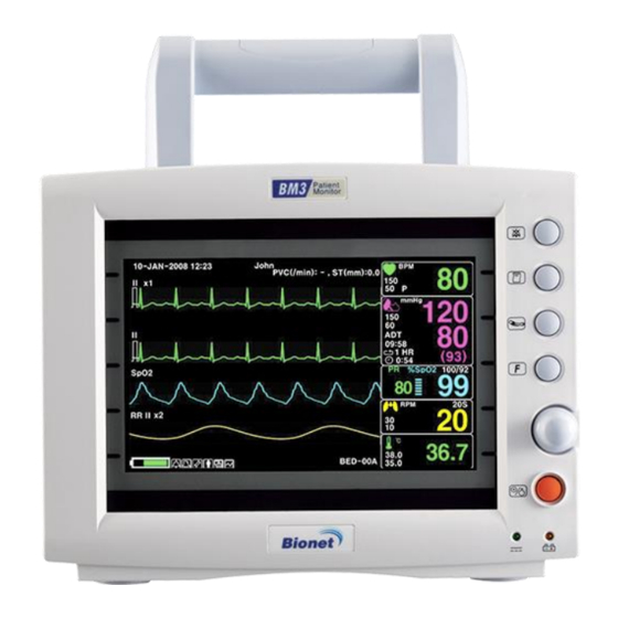
– DC adapter, 18VDC, 2.5A - Temperature probe Surface/Skin, reusable(OPTION) – rolls of paper. (OPTION) - 5-lead patient cable(OPTION) 4. Equipment Overview Overview of the Product BM3 monitor is a product used for monitoring biological information and Revision A - 14 -... -
Page 15: Features Of The Product
It also prints out waves and parameters via a printer. Features of the Product BM3 is a small-size multifunctional monitoring equipment for a patient designed to an easy usage during movement. It features devices for auto power supply (DC 10V-16V) and DC power supply (DC 18V) as well as installing its handle to the patient’s bed. - Page 16 BiONET Co. Ltd. Warning Users must pay attention on connecting any auxiliary device via LAN port or nurse calling. Always consider about summation of leakage current, Please check if the auxiliary device is qualified by IEC 60601-1, or consult your hospital biomedical...
- Page 17 www.BIO2NET.com Protective Ground Terminal DC Power Input Port Defib Sync RJ45 LAN Port RS-232C Serial Port /Nurse Call Back ECG Probe Connecter NIBP Probe Connecter Probe Connecter TEMP Probe Connecter ▲ ▼ Right side Left side Revision A - 17 -...
- Page 18 www.BIO2NET.com PRINTER Accessories ECG Cable ECG wire SpO2 Cable SpO2 Extention cable Revision A - 18 -...
-
Page 19: Equipment Symbols
www.BIO2NET.com (option) Temperature Cable NIBP CUFF TEMP(OPTION) Equipment Symbols ATTENTION : Consult accompanying documents TYPE CF APPLIED PART : Insulated (floating) applied part suitable for intentional external and internal application to the patient including direct cardiac application. “Paddles” outside the box indicate the applied part is defibrillator proof. - Page 20 www.BIO2NET.com Medical Standard Definition F-type applied part (floating/insulated) complying with the specified requirements of IEC 60601-1/UL 2601-1/CSA 601.1 Medical Standards to provide a higher degree of protection against electric shock than that provided by type B applied parts. Equipotentiality PAPER RS-232 AUX CONNECTOR DC INPUT INDICATOR...
-
Page 21: System Construction
www.BIO2NET.com 5. System Construction Block Diagram Revision A - 21 -... - Page 22 www.BIO2NET.com EXT. BOARD PRINTER BOARD ANALOG1 POWER DIGITAL BOARD (ECG, RESP.) SAFETY BOARD (POWER ON/ OFF, ANALOG2 NIBP FOR SAFETY (SpO2, NIBP, TEMP) FUNCTION) Digital Board Revision A - 22 -...
- Page 23 www.BIO2NET.com FROM POW ER 5V 7.2V GND MEMORY DC TO DC CONVERTER BACKUP M EM ORY (ROM(HY29LV160), (3.3V, 2.5V GENERATOR) (SRAM) SDRAM (K4S) RESET W ATCHDOG CLEAR TIMER LCD SIGNAL LAN CONTROLLER (BUFFER, LCD BIAS CONTRAST (S3C44BOX) (CS8900) VOLTAGE GENERATOR) CONTROL 3V BATTERY POW ER...
- Page 24 www.BIO2NET.com CPU components Samsung’s S3C44B0X is installed operating at the 3.5 times speed of 18.432MHz, 64.512MHz. The CPU includes the STN LCD CONTROLLER; Real Time Clock is installed inside allowing the activation of the interior clock, if the crystal of 32.768KHz and power are supplied. Memory components Consists of the ROM 2MByte (Hynix HY29LV160BT) and RAM 8MByte (Samsung K4S641632);...
- Page 25 www.BIO2NET.com Serial Controller Communicates with the analog board through two serial channels. Safety Board Cuts power off to the monitor and the pump in case of over pressure/over time to stablize NIBP; controls the overall power by receiving signals from power switch. DC INPUT (+ 10.5 ~ + 18) RELAY DC- DC CONVERTER...
- Page 26 www.BIO2NET.com DATA BUS (FROM DIGITAL BOARD) +7.2V (FROM DIGITAL BOARD) FIFO DATA BUS MOTOR CONTROL SIGNAL CPLD MOTOR DRIVER THERMAL PRINTER SIGNAL (TO MOTOR SIGNAL (TO MOTOR) PRINTER) Ext. Board Consists of the Speaker drive circuit, exterior serials and Dsync outputs Revision A - 26 -...
-
Page 27: Power Board
www.BIO2NET.com SERIAL D S YNC IN SPI BUS + 5V (FRO M D IGITAL BO A RD ) (FROM D IGITAL BOARD ) (FROM D IG ITAL BOARD ) D SYNC O UTPUT CIRCUIT D AC ISOLATED PO WER RS- 232 SERIAL D RIVER AUD IO AMP SPEAKER SERIAL O UT... -
Page 28: System Inspection
Power Supply Fuse An A.C Fuse of 250V/1.6A is built in the adapter. BM3’s POWER Borad is protected by Fuse 5A/125V connected with a Battery protection Fuse 5A/125V which protects the product. 6. System Inspection PRINTER Inspection contents - Pinter status... - Page 29 www.BIO2NET.com Inspection standards - Detect the paper - Normal operation in the speed 25mm/s, 50mm/s - Noise when you use print - Clear output Inspection procedure - Check the detection of the paper when the paper is in the device or not - Check the speed of the printing after changing the printing speed - Check the noise when print is working - Check the status of the print-output...
- Page 30 www.BIO2NET.com - Check the alteration after connecting the 5 leads ecg cable to simulator - Check the lead fault in the each lead - Check the gain of the printer-output after setting the 10hz sine wave in the simulator - Check the letter P in the display after setting the pace mode in the simulator - Check the size of the base noise after connecting the human body RESPERATION...
- Page 31 www.BIO2NET.com - Precision - No finger - Lead Fault Inspection standards - Amp. 0.3 , %spo2 96: +/- 2 - Detect the NO FINGER - Detect the lead fault Inspection procedure - Check the error by using the simulator ; Amp 0.3, % 96 - Check the message when you don't put the finger in the Probe - Check the message when the spo2 connector is disconnected from the main device...
- Page 32 www.BIO2NET.com - Check the message when the temp connector is disconnected from the main device NIBP Inspection contents - Precision - Set the Zero - Operate the OVP - Auto measurement Inspection standards - The mean values after measuring 5 times : +/- 5mmHg - Set the normal zero - adult : 290mmHg - Auto measurement in the auto-mode...
-
Page 33: Electrical Safety
www.BIO2NET.com Inspection standards - Control the volume of the sound - The alarm mode according the setting values & situation Inspection procedure - Check the volume level of the sound - Check the alarm sound after changing the ECG HR Electrical safety Inspection contents - Inspect the voltage... -
Page 34: Trouble Shoot
www.BIO2NET.com 7. Trouble Shoot 1. Noise in ECG The patient' s skin Apply ECG gel or water to the area - Gel is dry. is extremely dry of contact then use the electrode. - Electrodes does not stick well to skin The electrode is Replace the electrodes (Use CE in poor conditions... - Page 35 www.BIO2NET.com 3.Temp malfunction The probe is Replace the probe in bad c o n d itions Repair the Temp B/ D 4. NIBP malfuction Air leaks from the hose Replace the hose or cuff co n nec tor or c uf f Repair NIBP B/ D 5.
-
Page 36: Power Failure
www.BIO2NET.com 6. Failure in battery recharge (the battery does not fully recharge in 6 hours or more) Replace the adapter The outp ut vo ltag e o f the (the battery will not be charged at the rate ad ap ter is 18v lower than 17v) The b attery voltage Replace the battery... - Page 37 www.BIO2NET.com 9. Periodic noises All alarm has b een t urnd o f f Display lead f ault Turn f unctions not in use off messag e app ears (More- Display - Set para) The p rinter Replace the printer f unct io ns ab normally Repair the accompanying equipment...
-
Page 38: Exploded View
www.BIO2NET.com 8. Exploded View Revision A - 38 -... -
Page 39: Circuit Diagram
www.BIO2NET.com 9. Circuit Diagram Analog1 b/d, digital part BC 7 BC 8 VC C 3.3 0.1U F /Z 0.1U F /Z D EV_SW C LKOU T OSC 2/C LKOU T AC P 0.1U F /Z AC P R A0/AN 0 BC 3 4.7K/J U 22B... - Page 40 www.BIO2NET.com Analog1 b/d, Nibp part MP X5050GP N C 5 N C 4 C 18 N C 3 100N F /J BC 14 N C 2 0.1U F /Z N C 1 C 20 A GN D AGN D 1U F /Z R 21 R 22 10K/J...
- Page 41 www.BIO2NET.com Analog1 b/d, SpO2 part R 32 10/J R 33 R 35 3.3K/J 10/J 3.3K/J R 36 R 37 10K/J 10K/J R ED MMBT3906 MMBT3906 C 31 22K/J 10UF /35V 0.1UF /Z AGND 68K/J AGND U 11A U11B MC P602ISN 3.3K/J 3.3K/J MMBT3904...
- Page 42 www.BIO2NET.com Analog1 b/d, Temp part T_REF 0.1UF/K 1070/B AGND AGND TEMP1 OUT1 100K/F OUT2 0.1UF/K 5267-2 AGND AGND Revision A - 42 -...
- Page 43 www.BIO2NET.com Analog2 b/d, Digital part +5VA_1 +5VA_1 DEV_SW CLKOU T BC 8 +5VA_1 VCC 3.3 OSC2/CLKOU T 0.1UF /Z 0.1UF/Z R A0/AN 0 +5VA_1 R A1/AN 1 BC 1 R A2/AN 2 AGND _1 0.1UF/Z RA3/AN 3/VREF 220/J DEV_SW +5VA_1 U 10 U11A Vs s...
- Page 44 www.BIO2NET.com Analog2 b/d, ECG part 100K/ F 150K/F 1K/F +5VA_1 +5VA_1 24K/J 100K/J LM431 100/F 0.1UF/Z 10M/J 10M/J 10M/J 10M/J AGND_1 AGND_1 LEAD_R 100K/J AGND_1 AGND_1 +5VA_1 RA_R 10M /J 10M/J 10M/J 10M/J MMBT3904 100K/J 0.1UF/Z AGND_1 3.3K/J TL064CDR +5VA_1 AGND_1 470PF/K SA170CA...
- Page 45 www.BIO2NET.com Analog2 b/d, respiraton part -5VA_1 C 88 0.1U F/Z AGN D_1 TL062CD R C49 330PF/J C 48 330PF /J C 67 AGND _1 47K/F 0.1U F/Z -5VA_1 120K/F AGN D_1 +5VA_1 C 54 +5VA_1 0.1U F/Z AGN D_1 R 90 U 18A U 18B 1K/J...
- Page 46 www.BIO2NET.com Connector b/d ADAP_PWR DGND LTXD+ LTXD- 4 5 6 LRX D- CRX D DJ04-6P-4M LRX D+ CTXD CH508-04-ST XF10B11A-COMB01-4 0. 1UF/ Z/50/DI P 0.1UF/Z/50V/DI P DS03-09F-R DSYNC_OUT DGND FEMALE SGND ADAP_PWR DGND EJ210-2.0 LRX D- LRX D+ LTXD- LTXD+ CTXD DSYNC_OUT CRX D...
- Page 47 www.BIO2NET.com Digital b/d, I/F connector part LRX D- LRX D- VCC3.3 LRX D+ LRX D+ POWER_CHK VCC5.0 VCC7.5 POWER_CHK LTX D- VALVE_ON2 LTX D- AC_IN POWER_ON0 POWER_ON1 PORT0 PORT0 LTX D+ LTX D+ VALVE_ON0 VALVE_ON1 TxD0 MOTOR_ON PORT1 TxD0 PORT1 RxD0 TxD0 RxD0...
- Page 48 www.BIO2NET.com Dgital b/d, CPU part ADD R[0..22] AD C0 ADDR[0..22] ADC0 AD DR0 DATA0 ADDR[0..22] POWER_CHK AD DR1 DATA1 AD C1 POWER_CHK ADC1 AD DR2 DATA2 ADDR0 DATA[0. .15] AD DR3 DATA3 VCC3.3 ADDR1 AD C2 DATA[0..15] ADC2 AD DR4 DATA4 10NF/Z ADDR2...
- Page 49 www.BIO2NET.com Digital b/d, DC/DC converter part VCC5.0 VCC2.5 AIC1117-2.5 VCC5.0 VCC3.3 AIC1117A-3.3 VOUT VOUT HH-1M3216-601 HH-1M3216-601 HH-1M3216-601 HH-1M3216-601 Type : 3216 Type : 3216 Type : 3216 Type : 3216 10UF/35V 10UF/35V 10UF/35V 10UF/35V HH-1M3216-601 HH-1M3216-601 Type : 3216 Type : 3216 +2.5GND DGND VCC5.0...
- Page 50 www.BIO2NET.com Digital b/d, key b/d part V IN AC _IN V C C 3.3 R 32 VIN SW KE Y _C S IF _KEY 4 Ex IN T2 KE Y _C S U 23 R 11 0 100 K/J 미삽 VD D D A TA[0..1 5] 22 /J...
- Page 51 www.BIO2NET.com Digital b/d, LAN part VCC3.3 VCC3.3 ADDR[0..22] 4.99K/F DGND ADDR[0..22] VCC3.3 DATA[0..15] DATA[0..15] EECS ADDR[0..22] EESK EEDATAOUT ExINT[0..7] ADDR1 ExINT[0..7] EEDATAIN ADDR2 ADDR3 VCC3.3 AT93C46C27 LED 미삽 nGCS[0..7] 390/J VCC3.3 LINK DGND nGCS[0..7] LED0/HC0 VCC3.3 BSTATUS/HC1 RESET BC17 RESET LANLED 0.1UF/Z SA10...
- Page 52 www.BIO2NET.com Digital b/d, LCD connector part LCD_PVEE VCC3.3 U14A OVFRM 100/J VD[0..7] IIC_SCL 100/J OVLINE VD[0.. 7] OVCLK DVCC5. 0 100/J 100/J OV_PWR IIC_SDA LM358 VFRM VFRM OVD7 MAX5380MEUK-T 100/J OVD6 100/J VCC3.3 100/J OVD5 10UF/ 35V VLI NE OVD4 100/J VLINE OVD3...
- Page 53 www.BIO2NET.com Digital b/d, memory part VCC3.3 ADDR1 DATA0 ADDR2 DATA1 ADDR[0..22] nRESET ADDR3 DATA2 ADDR[0..22] nRESET VCC37 ADDR4 DATA3 ADDR1 DATA0 ADDR5 DATA4 ADDR2 DATA1 ADDR6 DATA5 DATA[0..15] ADDR3 DATA2 ADDR7 DATA6 DATA[0..15] ADDR4 DATA3 ADDR8 DATA7 ADDR5 DATA4 ADDR9 DATA8 ADDR6 DATA5...
- Page 54 www.BIO2NET.com Digital b/d, serial part RESET RX A RESET RX A UART_CS0 RX B VCC3.3 UART_CS0 RX B UART_CS1 UART_CS1 VCC3.3 EX TCLK EX TCLK R141 R142 10K/J 10K/J DATA5 RESET RESET DATA6 nDTRB DATA7 nDTRA RX B RX B nRTSA RX A RX A...
- Page 55 www.BIO2NET.com External B/d, Sound, serial part VC C5.0 VC C5.0 VC C9.1 VC C9.1 SVCC9.1 VC C3.3 R xD0 SVC C9.1 TxD0 SPI_TXD SPI_CLK DSYNC D SYN C_OUT BC 1 DGND DGND 1UF /Z FH01-14-DS-G 10UF/35V 1UF/Z U 5A SGND9.1 SVCC SOUND SGN D9.1...
- Page 56 www.BIO2NET.com Interface b/d J P3 GF120-30-TS POWER_SW POWER_SW POWER_ON0 POWER_ON0 POWER_SW POWER_ON0 POWER_ON1 NEW_POWER_CHK POWER_ON1 POWER_ON1 NEW_POWER_CHK VALVE_ON0 VALVE_ON1 NEW_POWER_CHK VALVE_ON0 VALVE_ON1 MOTOR_ON RxD0 VALVE_ON0 MOTOR_ON RxD0 TxD0 LRXD- VALVE_ON1 TxD0 LRXD- LRXD+ LTXD- MOTOR_ON LRXD+ LTXD- LTXD+ PORT0 RxD0 LTXD+ PORT0 PORT1...
- Page 57 www.BIO2NET.com Key b/d AC_IN VC C3.3 GF120-14-LS PHASE_A PHASE_B ROTARY _SW PHASE_A A_PHASE ROTARY _SW POWER _SW POWER_SW PHASE_B ACLED TACT SW B_PHASE BATLED (ENCODER) D GND EC11B15D0 DGND DGN D D GND AC_I N VCC3.3 LED/3/GREEN LED/3/Y ALLOW SW 3 SW 3 SW 5 TACT SW...
- Page 58 www.BIO2NET.com Power b/d 1/F/2012 VCC5.0 1/F/2012 220UH/2A 1/F/2012 KTB1151 FeedBack DIGI VALVE_ON2 POWER_ON0 1/F/2012 POWER_ON1 POWER_CHK M S22 470UF/35V/DIP VALVE_ON0 VALVE_ON1 Vout M OT OR_ON RxD0 1K/F T xD0 LRX D- 4.750V~5.275V LRXD+ LT X D- MS22 100UF/35V 100UH/5A On/Of f LTX D+ DGND PORT 0...
- Page 59 www.BIO2NET.com VC C 5. 0 VC C 7. 5 Printer Connector B/ D POWER VC C 7 .5 CABLE OP_D ATA OP_ STB3 PRINTER SIG OP_STB0 CABLE OP_STB1 OP_ STB2 OP_ LE OP_ STB4 OP_STB5 OP_C L K OP_ C LK OP_STB4 OP_ STB5 OP_STB2...
- Page 60 www.BIO2NET.com Printer b/d IF_F D0 D ATA0 IF_F D1 D ATA1 V CC3. 3 IF_F D2 D ATA2 VC C3.3 IF_F D3 D ATA3 D ATA4 IF_F D4 VCC 5.0 D ATA5 IF_F D5 V CC3 .3 IF_F D6 D ATA6 D ATA7 VCC3 .3 VCC3 .3...
- Page 61 www.BIO2NET.com Safety b/d SVI N +5VS +5VS +5VS VALVE_ON 2 POW ER _ON 0 POWER _ON 1 POW ER _C H K VALVE_ON 0 VALVE_ON 1 MOTOR_ ON RxD 0 BC 1 +5VS Tx D0 LRXD - 0. 1U F /Z 0.1U F / Z LR XD + LTXD -...
Need help?
Do you have a question about the BM3 and is the answer not in the manual?
Questions and answers