Table of Contents
Advertisement
Quick Links
Advertisement
Table of Contents

Related Manuals for CLF Lighting LED FAN


Summary of Contents for CLF Lighting LED FAN
- Page 1 WWW.CLF-LIGHTING.COM V1.0 NOVEMBER 2018...
-
Page 2: Table Of Contents
table of CONTENTS Dimensions Safety Instruction Fixture overview Introduction AC Power Power voltage Power cables Relaying power to other devices Data link Tips for reliable data transmission Physical installation Fastening the fixture to a flat surface Outdoor IP-rated fixtures Condensation/moisture inside housing Fixtures temperature specification Setup Control panel and menu navigation... -
Page 3: Dimensions
Dimensions All dimensions are in millimeters 80mm 700mm 700mm WWW.CLF-LIGHTING.COM... -
Page 4: Safety Instruction
Safety Instruction WARNING! Read the safety precautions in this section before installing, powering, operating or servicing this product. The following symbols are used to identify important safety information on the product and in this manual: DANGER! DANGER! WARNING! WARNING! WARNING! WARNING! WARNING! Safety hazard. - Page 5 PROTECTION FROM BURNS AND FIRE • The exterior of the fixture becomes hot during use. Avoid contact by persons and materials. Allow the fixture to cool for at least 5 minutes before handling. • Keep all combustible materials (e.g. fabric, wood, paper) at least 100 mm away from the fixture. •...
-
Page 6: Fixture Overview
Fixture overview ATTACHMENT POINTS G-HOOK ART. NO. 520113 or 520114 OMEGA BRACKET ART. NO. 875760 SAFETY CABLE ATTACHMENT POINTS SIDE SIDE FRONT BOTTOM BACK DISPLAY POWER OUT CONTROL BUTTONS DMX OUT POWER IN DMX IN WWW.CLF-LIGHTING.COM... -
Page 7: Introduction
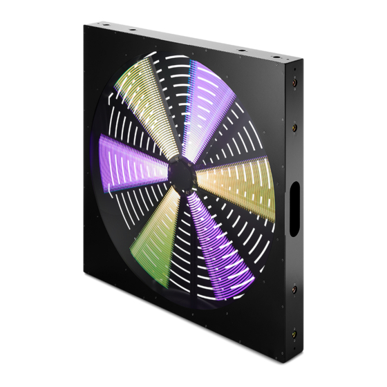
Introduction propeller like led effect ■ 6 fan blades ■ RGB LEDs ■ PowerCON True 1 in & out ■ Different mounting positions ■ LEDs controllable in two groups Using for the first time Warning! Read “Safety Information” before installing, powering, operating or servicing the fixture. Before applying power to the fixture: Check that the local AC mains power source is within the fixture’s power voltage and frequency ranges. -
Page 8: Power Cables
Power cables Power input and throughput cables must be rated 16A minimum, have three conductors 1.5 mm² (16 AWG) minimum conductor size and an outer cable diameter of 5 - 15 mm. Cables must be hard usage type (SJT or equivalent) and heat- resistant to 90°C minimum. In the EU the cable must be HAR approved or equivalent. -
Page 9: Physical Installation
Physical installation Warning! The fixture must be either fastened to a flat surface such as a stage or wall, or clamped to a truss or similar structure in any orientation using a rigging clamp. Warning! If the fixture can cause injury or damage if it falls, attach an approved safety cable to one of the safety cable attachment points on the base (see “Fixture overview”). -
Page 10: Outdoor Ip-Rated Fixtures
Outdoor IP-rated fixtures CLF products are applied to official classified IP norm levels. For this product the IP rate is IP20. solid object Moisture Protected against a solid object greater No protection than 50mm such as a hand. Protected against a solid object greater Protected against vertical falling drops of than 12.5mm such as a finger. -
Page 11: Setup
Setup Warning! Read “Safety Information” before installing, powering, operating the fixture. Control panel and menu navigation The onboard control panel and backlit graphic display are used to set the fixture’s DMX address, configure individual fixture settings (personality), read out data and execute service utilities. See “Onboard control menus” for a complete list of menus and commands. Using the control buttons •... -
Page 12: Control Mode
Control mode DMX control mode is selected in the CONTROL MODE menu. The fixture can be controlled with 2 DMX control modes: 11ch RGB group 1 RGB group 2 Master dimmer Color macro Macro speed Strobe Motor rotating WWW.CLF-LIGHTING.COM... -
Page 13: Onboard Control Menus
Onboard control menus Main menu Menu level 2 Menu level 3 Remark 001 - 507 (5CH) DMX address Set DMX start address 501 (11CH) 11CH Control mode Select DMX mode Auto 1 - 8 Select Auto program, LED Auto mode LED speed 1 - 10 and motor speed Motor speed 1 - 10... -
Page 14: Dmx Protocol
DMX protocol Channel 5 DMX value Functions Remark 000 - 255 Master dimming 0-100% Master Dimmer 000 - 010 No function 011 - 150 Static colors Color Macro 151 - 255 Color chasing 000 - 255 Macro speed from slow to fast Macro speed 000 - 010 Strobe open... -
Page 15: Exploded View
Exploded view Description Part number Description Part number Metal front cover CLF-80-024 Metal frame CLF-80-025 Plastic front cover CLF-80-022 Metal support bracket motor CLF-80-026 LED board CLF-80-019 Timing belt CLF-80-017 Metal support bracket LED board CLF-80-027 Step motor CLF-80-016 Main + display PCB CLF-80-021 Complete central rotating part CLF-80-023... -
Page 16: Specifications
Specifications Power Input voltage & rate 100~240V Nominal, 50/60 Hz Standby power Nominal total power consumption (at nominal voltage 230V) 180W Typical current (at nominal voltage 230V) 0,82A Cos φ 0.99 Power plug type PowerCON True Configuration LED color Quantity of LED 792 pcs Dimming frequency 4000Hz... - Page 17 Specifications Control Control protocol USITT DMX512/1990 DMX channel range 5/11 CH RDM compliance DMX input connection DMX 3pin and 5pin in/out Hardware Interface Full color LCD display Software upload method Via PCB Installation IP rating IP20 Housing Safety attachment point Physical Net product weight 11Kg...
- Page 18 CLFLIGHTING WWW.CLF-LIGHTING.COM...
Need help?
Do you have a question about the LED FAN and is the answer not in the manual?
Questions and answers