Table of Contents
Advertisement
Quick Links
Cautions, warnings, and regulatory information
READ AND SAVE THESE INSTRUCTIONS Follow the instructions in this
installation manual. These instructions must be followed to avoid damage
to this product and associated equipment. Product operation and reliability
depend upon proper installation.
DO NOT INSTALL ANY AUTOCALL™ PRODUCT THAT APPEARS
DAMAGED Upon unpacking your Autocall product, inspect the
contents of the carton for shipping damage. If damage is apparent,
immediately file a claim with the carrier and notify an authorized
Autocall product supplier.
ELECTRICAL HAZARD Disconnect electrical field power when
making any internal adjustments or repairs. All repairs should be
performed by a representative or an authorized agent of your local
Autocall product supplier.
STATIC HAZARD Static electricity can damage components. Handle
as follows:
• Ground yourself before opening or installing components.
• Prior to installation, keep components wrapped in anti-static
material at all times.
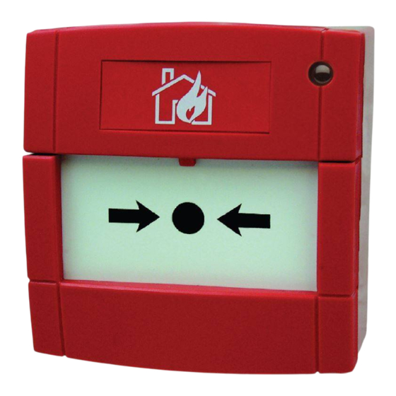
Indoor isolated callpoint
Figure 1: Indoor isolated callpoint
The indoor isolated callpoint is an addressable indoor manual callpoint. The
callpoint signals the condition of a switch contact that activates with a press
of a deformable element. After activation the callpoint can be reset. The unit
features a short-circuit isolator and is UL compliant. For details of the status
LED and activation see Table 4.
Table 1: Ordering information
Item
MCP - Indoor isolator
Resettable element (pack of 1)
Back box
Glass element (pack of 5)
Installating the callpoint
1.
Connect an 801AP MX Service Tool or an 850EMT into the programming
port, noting the orientation. Program the unit using the ID defined in the
site configuration.
2.
- To surface mount the callpoint, use the dedicated back box
(A4099-9711) to mount the callpoint to the wall.
- To flush mount the callpoint, use a standard single gang back box. The
back box must be at least 25 mm (0.98 in.) deep with fixing holes at
60.3 mm (2.37 in.) spacing.
3.
Route the loop wiring through the back box.
Order number
A4099-5208
515.001.127
A4099-9711
515.001.119
4.
Remove the callpoint sliding front plate and deformable element
assembly. This is described in the following section under 'replacing the
glass or deformable element'.
5.
Connect the loop wiring to the push-fit connector, see Figure 2.
6.
Connect the push-fit connector.
7.
Fix the callpoint to the back box using the supplied screws through the
exposed fixing holes.
8.
Re-fit the front plate assembly. Slide it into position then push upwards
until it clicks into place.
Figure 2: Installation
Table 2: Installation
Number
1
2
Table 3: Field wiring
Connector
A
B
C
D
MX Indoor Isolated Callpoint
Part
Programming port
Push-fit connector
Loop connection
+L
-L
+R
- R
579-1396AC Rev. A
*05791396ACA*
Advertisement
Table of Contents

Related Manuals for Johnson Controls Autocall MX Indoor Isolated Callpoint


Summary of Contents for Johnson Controls Autocall MX Indoor Isolated Callpoint
- Page 1 MX Indoor Isolated Callpoint Cautions, warnings, and regulatory information Remove the callpoint sliding front plate and deformable element assembly. This is described in the following section under 'replacing the READ AND SAVE THESE INSTRUCTIONS Follow the instructions in this glass or deformable element'. installation manual.
- Page 2 2.456 mA © 2021 Johnson Controls. All rights reserved. All specifications and other information shown were current as of document revision and are subject to change without notice. Additional listings may be applicable, contact your local Autocall product supplier for the latest status. Listings and approvals under Tyco Fire & Security GmbH, and the product names listed in this material are marks and/or registered marks.
Need help?
Do you have a question about the Autocall MX Indoor Isolated Callpoint and is the answer not in the manual?
Questions and answers