
Related Manuals for Vestfrost ULTF40


Summary of Contents for Vestfrost ULTF40
- Page 1 USER MANUAL - EN - UlTF 40 VTs098 VTs252 VTs254 VTs256 VTs258 models B I O M E D I C A L S O L U T I O N S FREEZERS...
-
Page 3: Table Of Contents
Vestfrost Solutions CONTENTS WARNING � � � � � � � � � � � � � � � � � � � � � � � � � � � � � � � � � � � � � � � 4 PRODUCT DESCRIPTION �... -
Page 4: Warning
Vestfrostsolutions.com WARNING As the appliance contains a flammable refrigerant, it is essential to ensure that the refrigerant pipes are not damaged. The quantity and type of the refrigerant used in your appliance is indicated on the rating plate. Standard EN378 specifies that the room in which you install your appliance must have a volume of 1m³... - Page 5 Vestfrost Solutions given supervision or instruction concerning use of the appliance in a safe way and understand the hazards involved. WARNING: Children shall not play with the appliance. WARNING: Cleaning and user maintenance shall not be made by children without supervision.
- Page 6 Vestfrostsolutions.com WARNING: The appliance must be connected to power minimum 12 hours before using it for storage of medicine. Always keep the keys in a separate place and out of reach of ● children. Do not step on the lower panel to reach medicine in the top of ●...
-
Page 7: Product Description
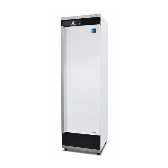
VTS 256 VTS 258 We recommend that you read this user manual before using the unit for the first time. Vestfrost Solutions does not guarantee safe operation if the unit is used for anything other than its intended use. Contents of the user manual can be subject to change without notice. -
Page 8: Electrical Connection
The rating plate provides various technical information as well as type and serial number. Product number Intended use Vestfrost biomedical freezers are designed to provide reliable temperature stability and precision and ensure an ideal cold temperature storage for sensitive items is achieved. The products are designed for the following operating ranges:... -
Page 9: Freezer Components
Vestfrost Solutions FREEZER COMPONENTS Front & internal view 1. Display – With integrated keyboard 2. USB port – Export historical data. See chapter Display components 3. Light – Only when door is opened 4. Lock – Push and turn lock. ´´Insert the key into the keyhole and push and turn the key 180 degrees clockwise´´. -
Page 10: Backview
Vestfrostsolutions.com Backview 1. Ventilation guards. See chapter Installation and Start-up. 2. Rating plate. 3. Porthole – Hole for external sensor or and CO2 backup. See chapter Installation and Start-up 4. Voltage free contact. See chapter Remote alarm function for more information. Battery backup button –... -
Page 11: Sensor Placement
Vestfrost Solutions Sensor placement 1. TR3 – Regulating probe. 2. External sensor – Use a 3.5mm cable tie to mounting for external sensor. The cable tie can be found in the plastic bag. -
Page 12: Display Components
Vestfrostsolutions.com Display components Models VTS252/254/256/258 Operation – main view: 1. The temperature in the appliance (measured by the TR3 probe) 2. Time and date 3. ALARM icon. Flashing by alarm turned on when there has been an alarm, but the alarm is no longer active. - Page 13 Vestfrost Solutions Models VTS098/ULTF 40 LEDS Each LED function is described in the following table. MODE Function Compressor enabled Flashing Anti-short cycle delay enabled An alarm is occurring Recording activated Battery status OK Flashing Battery is beeing charged Flashing Charging problem or battery failure °C/°F...
-
Page 14: Installation And Start-Up
Vestfrostsolutions.com INSTALLATION AND START-UP Ventilation guards The two ventilation guards are mounted before moving the appliance to it’s final placement. The guards function is to secure an absolute minimum of ventilation, if the appliance is pushed too close up against a wall. Steps: Tabeltop 1. -
Page 15: Battery Backup
Vestfrost Solutions Battery backup The appliance is equipped with a battery back up system, which supplies the controller with power at power failure. The back up system duration is 48 hours. Steps: Push the orange button to switch on the battery backup system. -
Page 16: Location And Ventiltation
Vestfrostsolutions.com Location and ventiltation This unit must be installed according to the below condition: If the unit is installed in a location against the below conditions, it’s specified performance may not be achieved or malfunction and acci- dence may occur. 1. -
Page 17: Levelling The Appliance
Vestfrost Solutions Levelling the appliance Make sure the appliance is level. It can be levelled by rotating the adjustable feet of the appliance. Be certain to lock the breaks for units equipped with casters. For some models the ‘’antislip base’’... -
Page 18: Porthole
Vestfrostsolutions.com Porthole Portholes are used to pass the temperature probe or nozzle of a back-up system in the chamber. Steps: See chapter ´´Freezer components´´ for placement of porthole on your device. 2. The rubber plug varies from the models. Please see the illustrations to the left to find your type of porthole. - Page 19 Vestfrost Solutions Porthole type 2: 1. Take out the two rubber plugs. 2. Place your sensor wire in the plug. 3. Press the two plugs tight into the porthole Use the cable tie from the helping plastic bag to mount your sensor.
-
Page 20: Remote Alarm Function
Vestfrostsolutions.com Remote alarm function Your device is equipped with a remote alarm connection to send alarm signals to a building management system, a monitoring unit, visual or acoustical warning device etc. The alarm output is managed freely by the Alarm built in controller of the unit. -
Page 21: Interior Fitting
Vestfrost Solutions INTERIOR FITTING The shelves can be repositioned. To remove the shelves the door must be opened at least 90°. 1. Remove shelf brackets from shelf rails. 2. Replace shelf brackets in desired position. max. 15kg... -
Page 22: Controller- Operation And Function
Vestfrostsolutions.com CONTROLLER- OPERATION AND FUNCTION Models VTS252/254/256/258 Start up: When the appliance is connected to the power supply, the keyboard will automatically start up. The start up view on the keyboard will show the different software installed on the control- ler of the appliance. - Page 23 Vestfrost Solutions Service menu: From the main view push the SERVICE key and the SERVICE menu is entered. See below picture: PROBES: Enter the probes, to see the measured tem- peratures. 1-4 probes is availa ble depending on model. PARAMETERS: Enter the setting of the parameters.
- Page 24 Vestfrostsolutions.com How to change language: 1. Enter the SERVICE menu 2. Select LANGUAGE sub-menu 3. Push the ENTER key and the LANGUAG menu is entered. 4. Push the SET key and then use the UP and DOWN keys to select the language and then the SET key to confirm it.
- Page 25 Vestfrost Solutions NOTE: THE KEY: IS USED TO STOP AND START LOGGING. Logged data will have this layout: Where TR3, EVP , TL1, TL2 = Value of probes. With probe failure or absence:” - “ symbol is displayed. Please note that 1-4 probes are available depending on model.
- Page 26 Vestfrostsolutions.com How to enter the Graph: 1. Enter the DATA menu 2. Select GRAPH sub-menu 3. Push the ENTER key and the GRAPH menuis entered. 4. By UP and DOWN keys chose the probe that has to be displayed. 5. Push the HOME key to get back to the main view.
- Page 27 Vestfrost Solutions “P1” Regulating probe TR3 failure Alarm output ON; Compressor output accord- ing to parameters Con and CoF “P2” EVP Probe Failure Alarm output ON; Other outputs unchanged “P3” Logging probe TL1 failure Alarm output ON; Other outputs unchanged “P4”...
-
Page 28: Models Vts098-Ultf040
Vestfrostsolutions.com Models VTS098-ULTF040 How to see and change the set Alarms The controller memorizes the last 100 alarms point: happened, together with their start and finish How to: See the Set point time. It’s possible to export the alarms as 1. -
Page 29: Maintenance
Vestfrost Solutions MAINTENANCE Frequency TASK Description Quar- Annu- terly ally Years ned- dede The compressor 1. Unplug unit from power supply compartment and 2. Remove the lower panel. the condenser must 3. Use a vacuum cleaner to remove be kept free of dust dust and dirt. -
Page 30: General Information
Vestfrostsolutions.com GENERAL INFORMATION Warranty, spare parts and service Warranty disclaimer Faults and damage caused directly or indirectly by incorrect operation, misuse, insufficient main- tenance, incorrect building, installation or mains connection. Fire, accident, lightening, voltage variation or other electrical interference, including defective fuses or faults in mains installations. Repairs performed by others than approved service centres and any other faults and damage that the manufacturer can substantiate are caused by reasons other than manufacturing or material faults are not covered by the warranty. -
Page 31: Disposal
Vestfrost Solutions DISPOSAL Information for Users on Collection and Disposal of Old Equipment and used Batteries These symbols on the products, packaging, and/or accompanying documents mean that used electrical and electronic products and batteries should not be mixed with general household waste. - Page 32 Page 1 of 1 Revision date: 04-02-2020 Drawing no.: 8120185-01 version www.vestfrostsolutions.com info@vestfrostsolutions.com...
Need help?
Do you have a question about the ULTF40 and is the answer not in the manual?
Questions and answers