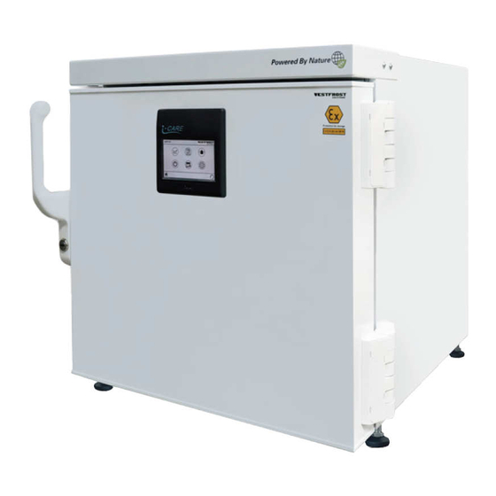
Summary of Contents for Vestfrost ULTF-37i
- Page 1 SERVICEMANUAL - EN - UlTF-37 models B I O M E D I C A L S O L U T I O N S FREEZERS...
-
Page 3: Table Of Contents
Vestfrost Solutions CONTENTS ATTENTION! � � � � � � � � � � � � � � � � � � � � � � � � � � � � � � � � � � � � � � 4 MAINTENANCE SCHEDULE �... -
Page 4: Attention
Vestfrostsolutions.com ATTENTION! Before servicing or cleaning nor assume any liability, for the appliance, unplug the injury or damage of any kind appliance from the mains arising from the use of this or disconnect the electrical manual� power supply� ATTENTION! ATTENTION! Bare pcbs are sensitive to This service manual is in- ESD, so please take precau-... -
Page 5: Replacement Of Parts
Vestfrost Solutions REPLACEMENT OF PARTS Top panel Loosen the screws see picture Pull the top panel straight out and place it on top of the unit. Unplug the wires from connector Note! Be careful not to damage electric wires and not to scratch the unit when placing... -
Page 6: Display - With Integrated Keyboard
Vestfrostsolutions.com Display - with integrated keyboard Tilt the appliance and release the touch panel by pushing in the plast lock and lifting up the panel simultanously Carefully demount the plug/wire from the touch panels back side... -
Page 7: Door Handle And Lock
Vestfrost Solutions Door handle and lock Carefully remove cover, gently pry with screwdriver in the notch on the bottom. Unscrew the bolt. Remove handle. Assemble the new handle as illustrated in the picture to the left. Now install the new handle. -
Page 8: Door
Vestfrostsolutions.com Door Use screwdriver to carefully remove the two hinge plastcaps hiding the hingescrews on the doorside. Remove the display, see page 6 Pull out the wire, cable ties may need to be removed... - Page 9 Vestfrost Solutions Support the door and remove the six hinge- screws. Use the handle to free the door from the cabinet, when the door is free lift it away from the hinges. Follow the step in chapter replacement of parts - handle.
- Page 10 Vestfrostsolutions.com Mount the new door by following the steps backwards. NOTE! Before mounting the hinge covers, make sure that the locking rings are turned around so that the wider area (with the holes) is facing as shown in the illustration The new door is mounted with a distance of 9 mm between door and front of steel cabinet Distance is adjusted for both hinge- and...
-
Page 11: Door Gasket
Vestfrost Solutions Door gasket Open the door and pull off the gasket you want to replace Push the new gasket foot into the profile. Note! Make sure that the new gasket is properly inserted in the profile. -
Page 12: Replacement Of Parts In Engine Room
Vestfrostsolutions.com REPLACEMENT OF PARTS IN ENGINE ROOM Access to engine room Take the IEC plug out of the unit. Loosen the 6 screws a few milimeters. Remove the backplate. Battery Controller Inverter Transformer Fuses Valve... -
Page 13: Inverter
Vestfrost Solutions Inverter Disconnect the electric wire on the inverter. Note! Ensure that the unit is unplugged and that there is no power on. Loosen two screws and remove inverter. Mount the NEW inverter with the screws you just unscrewed. -
Page 14: Battery
Vestfrostsolutions.com Battery Disconnect the electric wire on the battery. Note! Ensure that the unit is unplugged and that there is no power on. Cut and remove the cable ties. Take out the old battery and put in the NEW. Mount the new battery with two new cable ties. -
Page 15: Cooling System
Vestfrost Solutions COOLING SYSTEM Change compressor Repairs to the cooling system may only be carried out by trained professionals. When changing the compressor, the filter drier must also be replaced. Is is important to cut out the filter drier, as heating with solder flame will release moisture inside the dry filter. -
Page 16: Electrical System
Vestfrostsolutions.com ELECTRICAL SYSTEM Wire diagram... -
Page 17: Spare Parts
Vestfrost Solutions SPARE PARTS Spare parts exploded view... -
Page 18: Spare Parts List
Vestfrostsolutions.com ULTF-37i Spare parts list Position Item number Item name 0087 0-6038175 Base plate fittings, complete 0126 8-036510310 Compressor -ULTF40 0199 0-4838236 Key set 2 pcs EUROLOCKS / Kulcs szett ( 2 kulcs / szett ) 0593 0-4838095 Vacuum valve... -
Page 19: List Of Parameters
Vestfrost Solutions LIST OF PARAMETERS List of Ultra low parameters Profile name PROFILE 1 ‐ Ultra low Description Temperature range: ‐86C to ‐20C Set point: ‐82C INDEX PAR NAME VALUE UNIT 49 AD1 1 ADR 2 ALL 50 Tenth of°C/F 50 AD2 3 ALH 50 Tenth of°C/F 51 AD3 4 AAL ‐999 Tenth of°C/F 52 AD4 5 AAH 0 Tenth of°C/F... -
Page 20: List Of Lcp Parameters
31 TCO 50000 Millisec 32 BCO 3 Sec 33 PTD 0 Tenth of°C/F 34 FCE 350 Tenth of°C/F 35 MCT 580 Tenth of°C/F Vestfrostsolutions.com 36 FOP 2592 Bit flag 37 FAS 500 Tenth of°C/F 38 FAD 60 Sec 39 FSD 500 Tenth of°C/F 40 LET ‐250 Tenth of°C/F 41 DOP 0 Bit flag 42 DCM... -
Page 21: List Of Lcs Parameters
Vestfrost Solutions List of LCS parameters INDEX PAR NAME VALUE UNIT 1 PCT ‐1000 Tenth of°C/F 2 PHT 500 Tenth of°C/F 3 PCH 50 Tenth of°C/F 4 PHH 50 Tenth of°C/F 5 PCD 10 Sec 6 PHD 10 Sec 7 PCN 5 Unit 8 PCW... - Page 22 Vestfrostsolutions.com...
- Page 23 Vestfrost Solutions...
- Page 24 Revision date: 19-10-2022 Drawing no.: 8195131 rev 02 www.vestfrostsolutions.com info@vestfrostsolutions.com...


Need help?
Do you have a question about the ULTF-37i and is the answer not in the manual?
Questions and answers