Advertisement
Quick Links
Build Your Own Clone
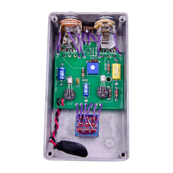
E.S.V. Fuzz (Silicon)
NPN Negative Ground
Kit Instructions
Warranty:
BYOC, Inc. guarantees that your kit will be complete and that all parts and components
will arrive as described, functioning and free of defect. Soldering, clipping, cutting,
stripping, or using any of the components in any way voids this guarantee. BYOC, INC
guarantees that the instructions for your kit will be free of any majors errors that would
cause you to permanently damage any components in your kit, but does not guarantee
that the instructions will be free of typos or minor errors. BYOC, INC does not
warranty the completed pedal as a whole functioning unit, nor do we warranty any of the
individual parts once they have been used. If you have a component that is used, but feel
it was defective prior to you using it, we reserve the right to determine whether or not the
component was faulty upon arrival. Please direct all warranty issues to:
sales@buildyourownclone.com This would include any missing parts issues.
Return:
BYOC, Inc. accepts returns and exchanges on all products for any reason, as long as they
are unused. We do not accept partial kit returns. Returns and exchanges are for the full
purchase price less the cost of shipping and/or any promotional pricing. Return shipping
Advertisement

Related Manuals for BYOC ESV Fuzz Silicon


Summary of Contents for BYOC ESV Fuzz Silicon
- Page 1 This would include any missing parts issues. Return: BYOC, Inc. accepts returns and exchanges on all products for any reason, as long as they are unused. We do not accept partial kit returns. Returns and exchanges are for the full...
- Page 2 That being said, we will do our best to help you as much as we can. Our philosophy at BYOC is that we will help you only as much as you are willing to help yourself. We have a wonderful and friendly DIY discussion forum with an entire section devoted to the technical support and modifications of BYOC kits.
-
Page 3: Table Of Contents
E.S.V. Fuzz (NPN) Kit Instruction Index Parts Checklist………………………....…..page 6 Populating the Circuit Board……....……..page 7 Main PCB Assembly..........page 16 Wiring………………………………......page 21 Orienting the Transistors/Finish up……..……..page 27 Operation Overview..........page 28 Schematic..............page 29... -
Page 6: Parts Checklist
Parts Checklist for ESV Fuzz NPN Silicon Kit Resistors: 1 - 330ohm (orange/orange/brown/gold) 1 - 4.7k (yellow/purple/red/gold) 1 - 33k (orange/orange/orange/gold) 1 - 100k (brown/black/yellow/gold) 1 - 1M (brown/black/green/gold) Trimpot: 1 - 25k trimmer Capacitors: 1 - 0.01uf film 1 - 2.2uf aluminum electrolytic 1 - 22uf aluminum electrolytic 1- 150pf ceramic disc Transistors:... -
Page 7: Populating The Circuit Board
Populating the Circuit Board Step 1: Add the transistor sockets. Make sure that the tab on the socket matches up with the tab on the circuit board. Do not add the transistors yet and do not solder the transistors to anything. Only solder the sockets. - Page 8 Step 2: Add all the resistors. Resistors are not polarized and can be inserted in either direction. Save the excess lead clippings from these resistors. You will need them to make jumpers in the next step. Use the 330 ohm resistor for silicon transistors. You would only want to use 470 ohm for germanium transistors.
- Page 9 Step 2: Use the left over lead clippings from the last step to make two jumpers that connect the “N” eyelets to the two unlabeled eyelets. These jumpers will make the circuit have a negative ground. If you were to make the jumpers to the “P” eyelets, that would give the circuit a positive ground.
- Page 10 Step 4: Add the bias trimpot. The board is designed to accept several brands of trimmers, but there is only one way to insert the trimpot that comes with the kit. Directions for setting the trimpot are in the “Finish Up” portion of the directions.
- Page 11 Step 5: Add the 0.01uf film capacitor. This is non-polarized so it can go in either direction.
- Page 12 Step 6: Add the aluminum electrolytic capacitors. These are polarized, meaning there is a positive and negative end. You will be able to identify the positive end by the indented collar around that side. For the 2.2uF cap, the positive end goes in the square solder pad. It should be obvious from the layout how to orient the 2.2uF.
- Page 13 Step 7: Add the 150pf ceramic disk capacitor if you’d like. This is not labeled on the PCB. This component was not part of the original fuzz face circuit. It prevents the higher gain silicon transistors from feeding back when you have the fuzz knob all the way up. We highly recommend that you add this capacitor.
- Page 14 Step 8: Add the battery snap. Thread the solder ends of the battery snap into the strain relief holes from the bottom solder side of the PCB and out through the top. Insert the solder ends of the battery snap wires into the topside of their respective solder pads.
- Page 15 Step 9: Add wires to the IN, OUT, RING, two Ground eyelets, and DC adapter eyelets. Start by cutting five 2.5” pieces of wire, and three 1” pieces. Strip 1/4” off each end and tin the ends. Tinning means to apply some solder to the stripped ends of the wires. This keeps the strands from fraying and primes the wire for soldering.
-
Page 16: Main Pcb Assembly
Main PCB Assembly Step 1: Mount the AC adapter jack to the enclosure. Your kit may come with either an external thread or internal thread. Don’t get confused by this. They still function exactly the same. You just thread the external nut on the outside and the internal nut on the inside. - Page 17 Step 2: Flip the PCB over so that the bottom or solder side is up. Insert the B1k (FUZZ) & A500k (VOLUME) potentiometers, and the LED into the bottom side of the PCB. DO NOT SOLDER ANYTHING YET!!! LED will have one lead that is longer than the other. MAKE SURE THE LONGER LEAD GOES IN THE HOLE MARKED “N”...
- Page 18 Step 3: Hold the PCB in one hand so that the component side of the PCB is in the palm of your hand and the bottom side with the pots, toggle switch and LED is facing up. Now use your other hand to guide the predrilled enclosure onto the PCB assembly so that the pots and LED all go into their respective holes.
- Page 19 Step 6: Connect the TIP (negative) terminal of the DC adaptor jack to the eyelet on the PCB labeled “-“. Connect the SLEEVE of the DC adaptor jack to the eyelet on the PCB labeled “+”. Connect the battery disconnect terminal of the DC adaptor jack to the eyelet on the PCB labeled “(+)”.
-
Page 21: Wiring
Wiring Stereo (input) Jack Mono (output) Jack Step 1: Install the 1/4” jacks to the enclosure. - Page 22 Step 2: Install the footswitch. Orient the footswitch so that the flat sides of the solder lugs are like the diagram below. NOTE: There are no actual number markings on the footswitch. There are two correct ways you can orient the footswitch. They are both 180 degrees of each other.
- Page 23 FOOT SWITCH SOLDER LUG DESIGNATIONS Step 3: Wiring the foot switch. Make a jumper between lugs 3 & 6 from clippings from the resistors. • Simply use your needle nose pliers to make a U shape & insert into lugs 3 &...
- Page 24 Cut a 1.5” piece of wire. Strip 1/8” of one end. Strip 1/2” off the • other end. Tin both ends. This will be used to connect lug/eyelet 4. The longer stripped end will be used to jumper lug 4 to 9. Cut two 1”...
- Page 25 Step 4: Install the foot switch into the enclosure if it isn’t already. Insert the foot switch wires into their respective eyelets on the PCB. You can insert them into the top side and solder on the top side as well. The solder pads should be large enough (if you are using a soldering iron that isn’t too big) to allow you to do this without burning the PVC coating on the wires if you are careful.
-
Page 27: Orienting The Transistors/Finish Up
Orienting Transistor’s/Finish up Step 1: Install the transistors Install the transistors. Do not solder the transistors. Simply push the lead wires into the appropriate socket holes. The transistor socket hole with the tab next to it will be the emitter. The lead wires on the germanium transistors will be rather long, so you will want to clip off the excess. -
Page 28: Operation Overview
There is no special trick to this. Simply turn the trimpot till it sounds good to you. Some people say that you must set the bias so that the collector of Q2 measures 4.5 - 5.5v, but this is only a matter of opinion. Trust your ears for this step. - Page 30 Please visit http://buildyourownclone.com/board for any technical support copyright 2013 BYOC, Inc.
Need help?
Do you have a question about the ESV Fuzz Silicon and is the answer not in the manual?
Questions and answers