Table of Contents
Advertisement
Quick Links
BYOC Gray Overdrive Kit Instructions
Warranty:
BYOC, Inc. guarantees that your kit will be complete and that all parts and
components will arrive as described, functioning and free of defect.
Soldering, clipping, cutting, stripping, or using any of the components in
any way voids this guarantee. BYOC, INC guarantees that the instructions
for your kit will be free of any major errors that would cause you to
permanently damage any components in your kit, but does not guarantee
that the instructions will be free of typos or minor errors. BYOC, INC does
not warranty the completed pedal as a whole functioning unit, nor do we
warranty any of the individual parts once they have been used. If you have a
component that is used, but feel it was defective prior to you using it, we
reserve the right to determine whether or not the component was faulty upon
arrival. Please direct all warranty issues to:
sales@buildyourownclone.com This would include any missing parts
issues.
1
Advertisement
Table of Contents

Subscribe to Our Youtube Channel
Related Manuals for BYOC Gray 1976


Summary of Contents for BYOC Gray 1976
- Page 1 BYOC Gray Overdrive Kit Instructions Warranty: BYOC, Inc. guarantees that your kit will be complete and that all parts and components will arrive as described, functioning and free of defect. Soldering, clipping, cutting, stripping, or using any of the components in any way voids this guarantee.
- Page 2 That being said, we will do our best to help you as much as we can. Our philosophy at BYOC is that we will help you only as much as you are willing to help yourself. If you clearly put very little effort into building your kit, and made a big mess because you were lazy and impatient, we’re...
- Page 3 8. If you answered yes to 6 and 7, what does the pedal do when it is in the "on" position? 9. Battery or adapter (if battery, is it good? If adapter, what type?) Also, please only post photos that are in focus. Copyrights: All material in this document is copyrighted 2022 by BYOC, Inc.
-
Page 4: Table Of Contents
Gray Overdrive Kit Instruction Index Parts Checklist……………………………………page 5 - 6 Example Photo……………………………………page 7 Populating the Circuit Board……………………page 8 - 14 Mounting PCB Assembly/Adapter Wiring……..page 15 - 19 Wiring…………………………………………….page 20 - 24 Finish up………………………………………….page 25 Operating Overview……………………………..page 26 Schematic…………………………………………page 27 PCB Map…………………………………………page 28 Trouble Shooting…………………………………page 29... -
Page 5: Parts Checklist
Parts Checklist for BYOC Gray Overdrive Kit Resistors: 1 - 100ohm (brown/black/black/black/brown) 2 - 4k7 (yellow/purple/black/brown/brown) 2 - 10k (brown/black/black/red/brown) 2 – 22k (red/red/black/red/brown) 2 - 470k (yellow/purple/black/orange/brown) 1 – 1M (brown/black/black/yellow/brown) Visit www.byocelectronics.com/resistorcodes.pdf for more information on how to differentiate resistors. - Page 6 1 - A100k (LEVEL) 1 - C500k (DRIVE) Hardware: 1 - drilled enclosure w/ 4 screws (optional) 1 - BYOC Gray Overdrive PCB 1 - 3PDT footswitch 2 - knobs (optional) 1 - AC adaptor jack (optional) 2 – ¼” jacks...
-
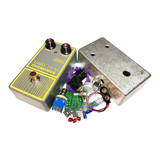
Page 7: Example Photo
This is what your Gray Overdrive should look like when you are finished. -
Page 8: Populating The Circuit Board
Populating the Circuit Board STEP 1: Add the diodes. Be sure to match the end of the diode with the stripe to the layout on the PCB. The stripped end should go in the square solder pad. FYI, the order in which these instructions tell you to populate the PCB is based on the profile height of the components. - Page 9 STEP 2: Add the resistors. Resistors are not polarized, so it does not matter which end goes in which solder pad. Take your time and be sure not to confuse similarly banded resistors such as the 4k7 with the 470k . Sometimes, certain colors can be very difficult to distinguish from batch to batch.
- Page 10 STEP 3: Add the 8 pin IC socket. ONLY SOLDER THE SOCKET! NOT THE ACTUAL IC! This is a socket. The sockets get soldered to the PCB. The ICs get inserted into the sockets. The actual IC chip itself, never gets soldered. You will insert the IC into the socket after the entire pedal has been built.
- Page 11 Step 5: Add the film capacitors. These are not polarized and can be inserted into the PCB either way.
- Page 12 STEP 6: Add the aluminum electrolytic capacitors. These are polarized. The positive end will have a longer lead and should go in the square solder pad. The negative end will have a shorter lead, usually with a black or white stripe running down the body of the capacitor.
- Page 13 Step 7: Add the battery snap. Thread the solder ends of the battery snap into the strain relief holes from the bottom solder-side of the PCB and out through the top. Insert the solder ends of the battery snap wires into the topside of their respective solder pads. Solder on the bottom side of the PCB.
- Page 14 Step 8: Add wire to the IN, OUT, RING, and two Ground eyelets. Use about 2 inches for each wire. This doesn’t need to be exact at this point. You will trim the wire to length later.
-
Page 15: Mounting Pcb Assembly/Adapter Wiring
Mounting the PCB Assembly and Connecting the DC Adapter Jack Step 1: Mount the DC adapter jack to the enclosure. Your kit may come with either an external thread or internal thread. Don’t get confused by this. They still function exactly the same and their solder terminals will appear exactly the same. - Page 16 Step 2: Flip the PCB over so that the bottom or solder side is up. Insert the A100k (LEVEL) and C500k (GAIN) potentiometers, and the LED into the bottom side of the PCB. DO NOT SOLDER ANYTHING YET!!! The LED will have one lead that is longer than the other.
- Page 17 Step 3: Hold the PCB in one hand so that the component side of the PCB is in the palm of your hand and the bottom side with the pots, toggle switch and LED is facing up. Now use your other hand to guide the predrilled enclosure onto the PCB assembly so that the pots and LED all go into their respective holes.
- Page 18 Step 6: Connect the TIP (negative) terminal of the DC adapter jack to the eyelet on the PCB labeled “-“. Connect the SLEEVE of the DC adapter jack to the eyelet on the PCB labeled “+”. Connect the battery disconnect terminal of the DC adapter jack to the eyelet on the PCB labeled “B”.
-
Page 20: Wiring
WIRING Step 1: Install the ¼” Enclosed jacks. The internal tooth lock washer goes on the inside of the enclosure. The flat washer goes on the outside of the enclosure. Note that these are “stereo” or “TRS” jacks. This is a mono effect, but we use a stereo jack for the INPUT JACK as the power on/off switch. - Page 21 FOOT SWITCH SOLDER LUG DESIGNATIONS Step 2: Begin wiring the foot switch. Orient the footswitch so that the flat sides of the solder lugs are like the diagram above. NOTE: There are no actual number markings on the footswitch. There are two correct ways you can orient the footswitch.
- Page 22 Step 2b: Cut a 3” piece of wire. Strip 1/2” off one end. Twist the stripped wire so that the strands are tight and then lightly tinned the exposed wire with solder. Don’t use too much or it will be too thick to pass through the solder lug holes.
- Page 23 Step 3: Install the foot switch into the enclosure. Step 4: Make all the wire connections between the foot switch and the jacks and the PCB as shown in the wiring diagram on the next page. The PCB has double-sided and plated through-hole eyelets, so it is okay to solder from the top side of the PCB.
-
Page 25: Finish Up
Installing the ICs and Finishing Up... -
Page 26: Operating Overview
Operating Overview Level: This controls the overall output volume. Gain: This controls the amount of distortion Power Supply: 9V battery or 2.1mm negative-tip 9VDC adapter. Current Draw: < 10mA Input Impedance: 470k ohms Output Impedance: 100k ohms... -
Page 28: Pcb Map
PCB Map The numbers above correspond to the component numbers on the schematic on the previous page. -
Page 29: Trouble Shooting
Trouble Shooting The overwhelming majority of our tech support issues are due to poor soldering….lazy, sloppy, impatient soldering. But even careful experienced pedal builders still make bad solder joints on occasion. If your pedal doesn’t fire up right out of the gate, you should reflow all your solder joints. - Page 30 1. Make sure your pedal has power. This not only means connecting a fresh 9V battery or 9VDC 2.1mm negative tip power supply. This also means plugging in a cable into the input jack. Don’t forget that the input jack acts as the power on/off switch.
- Page 31 If you need further technical support, please visit www.byocelectronics.com/board copyright 2022 B.Y.O.C., Inc.
Need help?
Do you have a question about the Gray 1976 and is the answer not in the manual?
Questions and answers