Advertisement
Quick Links
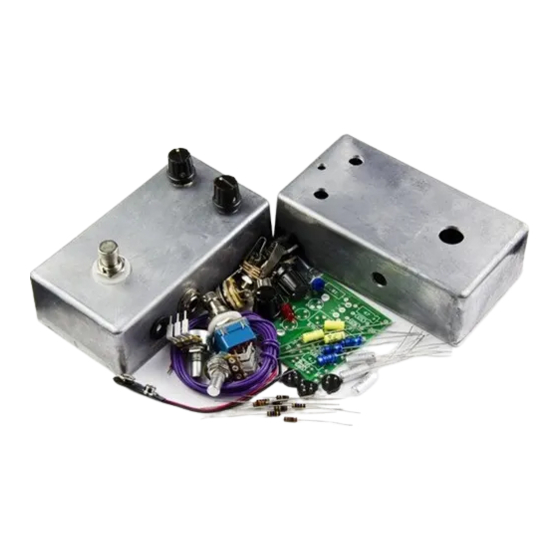
BYOC E.S.V. 2-knob Bender Kit Instructions
..............
Mounting the PCB.................................................page 7 - 9
THIS PEDAL HAS A POSITIVE GROUND! YOU DO NOT
NEED TO USE A SPECIAL POWER SUPPLY WITH
REVERSE POLARITY. BUT YOU CANNOT USE THIS
PEDAL ON A DAISY CHAIN WITH OTHER
NEGATIVELY GROUNDED PEDALS.
Copyright 2008 Build Your Own Clone
Advertisement

Related Manuals for BYOC E.S.V.


Summary of Contents for BYOC E.S.V.
-
Page 1: Table Of Contents
BYOC E.S.V. 2-knob Bender Kit Instructions Parts Checklist ....page 2 Populating the Circuit Board ....page 3 - 5 Assembly ....page 6 Mounting the PCB..........page 7 - 9 Wiring .....page 10 Finish up ....page 11-12 Troubleshooting Guide/Schematic.............page 13 - 19... -
Page 2: Parts Checklist
Parts Checklist for BYOC ESV 2-Knob Bender Kit Resistors: 1 - 470ohm (yellow/purple/brown/gold) 1 - 4.7k (yellow/purple/red/gold) 1 - 10k (brown/black/orange/gold) 1 - 47k (yellow/purple/orange/gold) 2 - 100k (brown/black/yellow/gold) 1 - 1M (brown/black/green/brown) Capacitors: 2 - .01uf film 1 - .1uf film 2 - 4.7uf aluminum electrolytic... -
Page 3: Populating The Circuit Board
Populating the Circuit Board Step1: Add the resistors. Resistors are not polarized so they can go in the PCB in either direction. The 1M resistor highlighted in yellow is added for footswitch pop reduction. Omitt this component if you want to keep the pedal as original as possible. It has little to no sonic affect on the circuit. Step 2: Add the larger black plastic diode with silver stripe(1N4001). - Page 4 Step 3: Add the transistor sockets. DO NOT SOLDER THE TRANSISTORS TO THE SOCKETS!!!!!!!!!!! Only solder the sockets to the PCB. Make sure to match the tab of the socket to the tab of the PCB layout. Step 4: Add the bias trimpot. Do not be confused by the fact that the PCB has holes for 5 legs and the actual trimpot only has 3.
- Page 5 Step 5: Add the yellow radial leaded metal film capacitors. These are not polarized and can go in the PCB in either direction. Step6: Add the aluminum electrolytic capacitors. These are polarize. The positive end goes in the square solder pad. The positive end will have an indented ring around one end...
-
Page 6: Assembly
Assembly 1. Install the jacks first. If you are looking down inside the enclosure, the mono jack goes on the right side and the stereo jack goes on the left. Place the washer on the outside of the enclosure. Use a 1/2" wrench to tighten 2. - Page 7 Mounting the Circuit Board PC Mounted Potentiometers: Some kits will come with PC mounted pots depending upon availability. If your kit has PC mounted pots follow these steps for mounting the circuit board. Step1: Understand that the LED, and both potentiometers will be mounted and soldered directly to the underside of the PCB.
- Page 8 Step 3: Now mount the PCB with LED onto the leads of the potentiometers. This move may take a little finess. It's best to leave your pots somewhat losely mounted to the enclosure so that you can easily move them to line up with the eyelets on the PCB. You may need to bend the leads of the pots into place if they were bent in shipping.
-
Page 9: Mounting The Pcb
Do not clip the leads of the pots. Solder Lugged Pots: Some kits may come with panel mounted pots with solder lug termination. If you kit has these style pots, follow these steps for mounting the PCB. Step 1: Connect the pots to their eyelets on the PCB with hook up wire. Insert the wires from the underside of the PCB and solder on the topside. -
Page 10: Wiring
WIRING... -
Page 11: Finish Up
Finishing Touches Add the OC75 transistors to their sockets. DO NOT SOLDER THEM!!!!!!!! DO NOT CLIP THEIR LEADS!!!!!!!!!!! Soldering or clipping them will void your warranty. We will not accept returns is they are used. Install your transistors into their sockets with full leads to test the pedal first. When you know that your pedal works and sounds the way you expect it to, then clip the leads and re-install the transistors. - Page 12 secure. If your transistors come out easily, then you have not installed them correctly and you will likely not get a good connection, and this will likely lead to a poor sounding pedal. Once you have installed your transistors, adjust the bias trimpot to taste. You can use your ear for this.
-
Page 13: Troubleshooting Guide/Schematic
Trouble Shooting Guide... - Page 14 Checking your wiring 1. NO POWER: If you have a completely dead pedal and your LED will not light up, this is usually a good sign that you are not getting power to the circuit. First you need to make sure that you are using a fresh battery or good power supply. . Also make sure you have a plug in the IN jack.
- Page 15 *If you do not get continuity between lugs 8 and 9 and you are certain that the footswitch is in the bypass state, then you likely have a faulty footswitch. 3. BYPASS WORKS, BUT THE EFFECT DOES NOT: This could be any number of problems located on the PBC, but let's check your offboard wiring first and make sure that you are getting signal to and from the PCB to rule that problem out.
- Page 16 Checking your PCB Ok..So Now you know bypass is working, signal is getting to and from the PCB, and that the PCB also has a connection to +9V and ground. If you're still haveing trouble, it's time to check your work on the PCB. Keep in mind that the PCB is simply a means of connecting one component or wire to another component or wire.
- Page 17 2. Check all Full Voltage connections. . Set your DMM to test for 9VDC. Touch the red probe to the sleeve of either jack. Touch the black probe to the various black test locations on the PCB. You should get 9V at all black locations. 4.
- Page 18 BLUE12 then it is likely Q2. And if it doesn't begin until BLUE16, then it is likely Q3. If you signal stops abruptly at BLUE6, 12, or 16, then the corresponding transistor is likely completey dead or there is a problem at one of the GREEN locations. ©2008 byoc, LLC...
Need help?
Do you have a question about the E.S.V. and is the answer not in the manual?
Questions and answers