Advertisement
Quick Links
Build Your Own Clone
Echo Royal
Kit Instructions
(Rev 1.2)
Warranty:
BYOC, Inc. guarantees that your kit will be complete and that all parts and components
will arrive as described, functioning and free of defect. Soldering, clipping, cutting,
stripping, or using any of the components in any way voids this guarantee. BYOC, INC
guarantees that the instructions for your kit will be free of any majors errors that would
cause you to permanently damage any components in your kit, but does not guarantee
that the instructions will be free of typos or minor errors. BYOC, INC does not
warranty the completed pedal as a whole functioning unit, nor do we warranty any of the
individual parts once they have been used. If you have a component that is used, but feel
it was defective prior to you using it, we reserve the right to determine whether or not the
component was faulty upon arrival. Please direct all warranty issues to:
sales@buildyourownclone.com This would include any missing parts issues.
Return:
BYOC, Inc. accepts returns and exchanges on all products for any reason, as long as they
are unused. We do not accept partial kit returns. Returns and exchanges are for the full
purchase price less the cost of shipping and/or any promotional pricing. Return shipping
is the customer's responsibility. This responsibility not only includes the cost of
shipping, but accountability of deliver as well. Please contact
sales@buildyourownclone.com to receive a return authorization before mailing.
Tech Support:
BYOC, Inc. makes no promises or guarantees that you will successfully complete your
kit in a satisfactory manor. Nor does BYOC, Inc. promise or guarantee that you will
1
Advertisement

Related Manuals for BYOC Echo Royal


Summary of Contents for BYOC Echo Royal
- Page 1 This would include any missing parts issues. Return: BYOC, Inc. accepts returns and exchanges on all products for any reason, as long as they are unused. We do not accept partial kit returns. Returns and exchanges are for the full purchase price less the cost of shipping and/or any promotional pricing.
- Page 2 That being said, we will do our best to help you as much as we can. Our philosophy at BYOC is that we will help you only as much as you are willing to help yourself. We have a wonderful and friendly DIY discussion forum with an entire section devoted to the technical support and modifications of BYOC kits.
-
Page 3: Table Of Contents
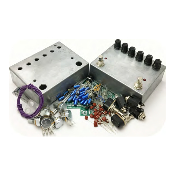
Echo Royal Kit Instruction Index Parts Checklist----------------------------------------------page 5-6 Populating the Circuit Board----------------------------page 8-15 Main PCB Assembly---------------------------------------page 16-21 Wiring---------------------------------------------------------page 22-24 Operation Overview----------------------------------------page 25-26 Schematic-----------------------------------------------------page 28... - Page 4 This is what your kit should look like when it’s complete. Your kit may come with different color capacitors, switches ect. Don’t be alarmed by this. They all still do the exact same thing.
-
Page 5: Parts Checklist
Parts Checklist for the Echo Royal Kit Resistors: (Metal Film (5 Bands) / Carbon Film (4 Bands)) 4 - 22R/22 (Red/Red/Black/Gold/Brown) / (Red/Red/Black/Brown) 3 - 470R/471 (Yellow/Purple/Black/Black/Brown) / (Yellow/Purple/Brown/Gold) 3 - 1k/102 (Brown/Black/Black/Brown/Brown) / (Brown/Black/Red/Gold) 3 - 3k3/332 (Orange/Orange/Black/Brown/Brown) / (Orange/Orange/Red/ Gold) - Page 6 1 - C500k RATE 1 - 50k Trimpot Hardware: 1 - predrilled enclosure w/ 4 screws 1 - Echo Royal Printed Circuit Board 2 - momentary footswitch 3 - Enclosed jacks 4 – rubber bumpers 3 – lock washers (for in and out jacks) hook-up wire Your kit will come with mostly 1/8 watt resistors.
-
Page 8: Populating The Circuit Board
Populating the Circuit Board Step 1: Add all the resistors. Resistors are not polarized and can be inserted into the PCB in either direction, meaning you don’t have to worry about orienting them. - Page 9 Add the diodes. Be sure to match the end of the diode with the stripe Step 2: to the layout on the PCB. The striped end should go in the square solder pad.
- Page 10 Step 3: Add the IC sockets. Be sure to align the notch on the IC sockets with the notch on the PCB screenprint.
- Page 11 Step 4: Add the transistors. Be sure to match the flat side of the transistor with the flat side of the transistor on PCB layout. Red outline is 2N3904, blue outline is 78L05, green outline is 2SK246, and the yellow outline is for the JFETs.
- Page 12 Step 5: Add the film and ceramic disc capacitors. These are non-polarized so they can go in either direction. The ceramic disc capacitors are highlighted in yellow, and are also non-polarized. The “473” highlighted in pink is a .047 film cap and will go on the underside of the PCB.
- Page 13 When placing the .047uF film capacitor on the underside of the PCB, bend it so it lies as flat as you can on the PCB. It is recommended to bend the capacitor away from the LED hole as shown below.
- Page 14 Step 6: Add the trimpot. This limits the amount of repeats. Most people what to set this so that the repeats eventually fade away after 10 seconds or so when the repeats knob is full turn clockwise. If you want infinite repeats, turn this trimpot up a little more. If you want self-oscillation (when the repeats runaway and keep getting louder) turn it up even more.
- Page 15 Step 7: Add the aluminum electrolytic capacitors. These ARE polarized, meaning there is a positive and negative end. The positive side will have a longer lead and goes in the square solder pad. The negative side will have a shorter lead and a stripe running along the body of the cap, and goes in the round solder pad.
-
Page 16: Main Pcb Assembly
Main PCB Assembly Step 1: Prepare the footswitches. Cut four 2 inch pieces of wire and solder them to the footswitches as shown. - Page 17 Step 2: Install the footswitches in the enclosure. Orient the footswitches so the solder lugs are facing each other...
- Page 18 Step 3: Flip the PCB over so that the bottom or solder side is up. Insert the potentiometers, toggle switch, and the LEDs into the bottom side of the PCB. IF YOUR POTS HAVE COVERS, REMOVE THEM BEFORE CONTINUING. YOU MIGHT HAVE TO CUT A SLIT IN THE COVER WITH A BLADE AND USE A SMALL SCREWDRIVER TO GET LEVERAGE. DO NOT SOLDER ANYTHING YET!!! The LEDs will have one lead that is longer than the other. THIS WILL GO INTO THE SQUARE SOLDER HOLE.
- Page 19 Step 4: Hold the PCB in one hand so that the component side of the PCB is in the palm of your hand and the bottom side with the pots, toggle switch and LED is facing up. Now use your other hand to guide the predrilled enclosure onto the PCB assembly so that the pots, toggle switch and LED all go into their respective holes.
- Page 20 You will want to place the jacks into the enclosure so the sleeve terminal is facing the right like the picture above. Be sure to remember the lock washers so the jacks don’t spin on their own.
- Page 21 This is what your build should look like at this point. Notice the tip terminal of the AC jack is upwards, and to the left. Also note that the SLEEVE terminals of the enclosed jacks are all facing right.
-
Page 22: Wiring
WIRING Step 6: attach the footswitches to the “SW1” and “SW2” spots as shown below... - Page 23 Step 7: Connect the TIP (negative) terminal of the DC adapter jack to the eyelet on the PCB labeled “-“. Connect the SLEEVE of the DC adapter jack to the eyelet on the PCB labeled “+” farthest to the right. Also connect the enclosed audio jacks to the PCB.
-
Page 25: Operation Overview
Operating Overview Blend: Controls the dry to delay ratio. Repeats: Controls the amount of repeats in the delay. Depth: Depth control for the modulation. Rate: Rate control for the modulation Delay: Sets the delay time. Tap Multiplier: Used for Tap Tempo switch. The sweep is divided into five sections. The five sections are listed below. - Page 26 Operating Instructions To engage the delay effect, hit the left footswitch. When the delay effect is active, the Blend control is a dry/delay(wet) blend. With the knob at noon, you will get a 50/50 mixture, all the way left is just the dry signal, and all the way right is the wet signal. The Repeats knob controls how many times the delayed signal will repeat.
- Page 27 Back-side PCB Photo...
- Page 29 For hi-res schematic visit http://www.byocelectronics.com/echoroyalschematic.pdf Please visit http://byocelectronics.com/board For any technical support Copyright 2019 BYOC, Inc.
Need help?
Do you have a question about the Echo Royal and is the answer not in the manual?
Questions and answers