PEERLESS SR1M Installation And Assembly Manual
32" - 60" flat panel tv cart
Hide thumbs
Also See for SR1M:
- Technical data sheet (2 pages) ,
- Installation and assembly manual (13 pages) ,
- Installation and assembly manual (13 pages)
Advertisement
Quick Links
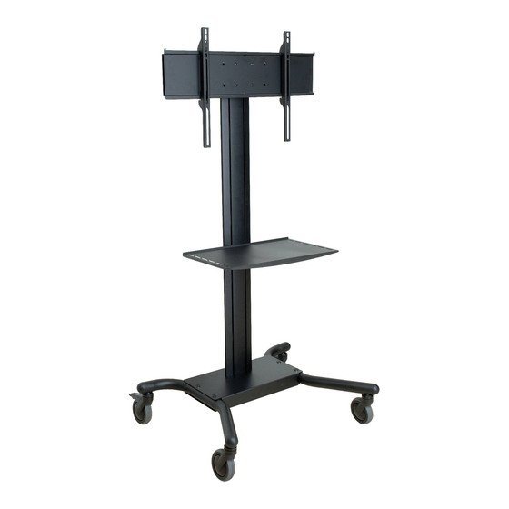
Installation and Assembly: 32" - 60" Flat Panel TV Cart
Models: SR1M, SR560M
3215 W. North Ave. • Melrose Park, IL 60160 • (800) 729-0307 or (708) 865-8870 • Fax: (708) 865-2941 • www.peerlessmounts.com
This product is UL Listed. It must be
installed by a qualified professional
R
installer.
Max UL Load Capacity:
150 lb (68 kg) screen
50 lb (22.7 kg) per shelf
ISSUED: 01-10-07 SHEET #: 009-9039-2 03-12-07
Advertisement

Related Manuals for PEERLESS SR1M


Summary of Contents for PEERLESS SR1M
- Page 1 Installation and Assembly: 32" - 60" Flat Panel TV Cart Models: SR1M, SR560M This product is UL Listed. It must be installed by a qualified professional installer. Max UL Load Capacity: 150 lb (68 kg) screen 50 lb (22.7 kg) per shelf 3215 W.
-
Page 2: Table Of Contents
Note: Read entire instruction sheet before you start installation and assembly. WARNING • Do not begin to install your Peerless product until you have read and understood the instructions and warnings contained in this Installation Sheet. If you have any questions regarding any of the instructions or warnings, please call Peerless customer care at 1-800-729-0307. -
Page 3: Parts List
Before you begin, make sure all parts shown are included with your product. Parts may appear slightly different than illustrated. Parts List SR1M SR560M Description Qty. Part Number Part Number screen mount bracket 201-1156 201-1156 hook plate 201-1157 201-1157 shelf support... - Page 4 Some parts may appear slightly different than illustrated. 4 of 14 ISSUED: 01-10-07 SHEET #: 009-9039-2 03-12-07...
-
Page 5: Assembling Cart
Insert four end caps (Y) into ends of left and right support legs (R & S) as shown. Guide left leg (R) towards base housing (D) as seen in fig.2.1. Then line up holes in base housing with holes in left leg. Fasten base housing to left leg using two 3/8-16 x 1.5"... - Page 6 Insert and screw casters (U & T) into holes of support legs (S & R). Attach casters with brake (U) to the back of left and right support legs. Attach casters without brake (T) to front of support legs as shown. NOTE: Lock brakes on casters to avoid sudden movements during installation.
- Page 7 Loosely attach four 1/4-20 x 12 mm screws (I), washers (K), and 1/4-20 nuts (J) to shelf support (C). Slide shelf support (C) onto upright (G) so that 1/4-20 nuts (J) slide into slots of upright (G) as shown in figure 6 and detail 1.
- Page 8 Attaching Metal Shelf Attach shelf pan (P) to shelf support (C) using six 8/32 nylock nuts (O) as shown below. Use an adjustable wrench to tighten six 8/32 nylock nuts (O). 8 of 14 ISSUED: 01-10-07 SHEET #: 009-9039-2 03-12-07...
- Page 9 Loosely attach six 1/4-20 x 12 mm screws (I), Slide screen mount bracket (A) onto upright (G) so washers (K), and 1/4-20 nuts (J) to screen mount that 1/4-20 nuts (J) slide into slots of upright (G) as bracket (A). shown in figure 9 and detail 2.
-
Page 10: Attaching Screen Using Universal Plate With Adapter Brackets
Attaching Screen using Universal Plate with Adapter Brackets For attaching screens with VESA 100 hole pattern, skip to page 13. For attaching Dedicated plate skip to page 14. Attach universal plate (E) to hook plate (B) using four Attach hook plate (B) to screen mount bracket (A). M10 x 15 mm socket screws (OO). - Page 11 Installing Adapter Brackets Refer to Screen Compatibility Chart to determine the proper fasteners to use. To prevent scratching the screen, set a cloth on a flat, level surface that will support the weight of the screen. Place screen face side down. If screen has knobs on the back, remove them to allow the adapter brackets to be attached. Place adapter brackets (F) on back of screen, align to holes, and center on back of screen as shown in figure 15.1.
- Page 12 Mounting and Removing Flat Panel Screen WARNING • Always use an assistant or mechanical lifting equipment to safely lift and position the plasma television. Hook adapter brackets (F) onto universal plate (E), then slowly swing screen in as shown. Turn screws (F) clockwise at least six times to prevent screen from being removed as shown in detail 4.
-
Page 13: Attaching Screen With Vesa 100 Mounting Pattern
Attaching Screen with VESA 100 Mounting Pattern WARNING • If screws don't get three complete turns in the screen inserts or if screws bottom out and hook plate is still not tightly secured, damage may occur to screen or product may fail. Choose hole pattern as shown in figure 17. -
Page 14: Attaching Screen Using A Dedicated Plate
14 of 14 ISSUED: 01-10-07 SHEET #: 009-9039-2 03-12-07 © 2007 Peerless Industries, Inc. All rights reserved. Peerless is a registered trademark of Peerless Industries, Inc. All other brand and product names are trademarks or registered trademarks of their respective owners.
Need help?
Do you have a question about the SR1M and is the answer not in the manual?
Questions and answers