Table of Contents
Advertisement
Quick Links
Advertisement
Table of Contents

Related Manuals for sewerin Multitec 520


Summary of Contents for sewerin Multitec 520
- Page 1 Multitec ® Operating instructions...
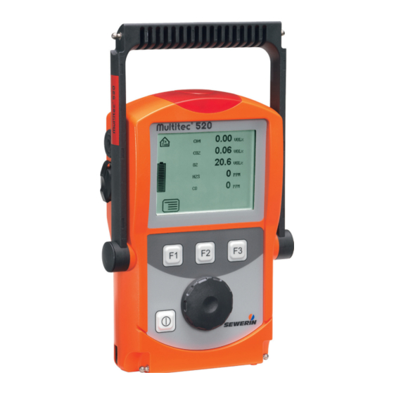
- Page 2 Signal light Buzzer Gas input USB port Display Function keys Jog dial ON/OFF key Connection for Connector power supply Fig. 1: Multitec 520 device overview Alarm Measured value Unit Warning %LEL ExTox symbol 0.17 VOL% 11.5 VOL% Capacity disposable battery/...
- Page 3 Display symbols Menu Fault Carry out device inspection Cancel (jump to next input field) Buzzer off Clear Save Information Stop measurement Warning ExTox Capacity Open stored comment disposable battery/ Open stored inspector rechargeable battery...
- Page 4 Information about this document The warnings and notes in the document mean the following: DANGER! Risk of personal injury. Results include serious injury or death. WARNING! Risk of personal injury. Can result in serious injury or death. CAUTION! Risk of personal injury. Can result in injury or a risk to health.
-
Page 5: Table Of Contents
Contents Page General ..................1 Warranty ..................1 Purpose ..................2 Intended use ................3 General safety information ............4 Features ...................5 Visual and audible signals ............5 Sensors ..................6 Explosion protection ..............7 2.3.1 Passive explosion protection ..........7 2.3.2 Active explosion protection ............8 Operation .................9 General information on operation ..........9 3.1.1 Keys and jog dial ..............9 3.1.2... - Page 6 Contents Page Power supply .................25 Suitable disposable/rechargeable battery types .....25 Operation with rechargeable batteries ........26 4.2.1 Charging ................27 4.2.2 Rechargeable battery maintenance ........27 Battery alarm ................28 Replacing disposable/rechargeable batteries ......29 Maintenance ................30 Device inspection ..............30 5.1.1 General information on the device inspection ......30 5.1.1.1 Scope ................30 5.1.1.2...
- Page 7 Contents Page Faults ..................48 Appendix ................49 Specifications and permitted operating conditions ....49 Alarms ..................50 7.2.1 Features ................50 7.2.2 Occupational exposure limits (OELs) and excess factors (STEL and LTEL) .........53 7.2.3 Alarm thresholds (factory settings) ........53 7.2.4 Setting ranges for gas types ..........54 Limit values for the device inspection ........55 Memory capacity ..............56 Sensors ...................57...
-
Page 8: General
● Repairs and maintenance must only be carried out by special- ist technicians or other suitably trained personnel. Only spare parts approved by Hermann Sewerin GmbH may be used when performing repairs. ● Use only suitable battery types, otherwise the device will not be explosion-proof. -
Page 9: Purpose
1 General Purpose The Multitec 520 is a portable warning device for monitoring the atmospheric air in the workplace. The device can measure up to six gases simultaneously, thus offering comprehensive protection against dangerous gas concentrations. It warns, for example, of: ●... -
Page 10: Intended Use
1 General Intended use This device is intended for professional residential and commer- cial use including small firms and commercial operations. The appropriate specialist knowledge is required to operate the device. The device may only be used to measure the following gases (depending on additional equipment): ●... -
Page 11: General Safety Information
1 General General safety information ● The device has been tested to ensure that it is explosion-proof in accordance with European standards (CENELEC). ● The device must only be switched on with fresh air. ● Do not use this device in oxygen-enriched atmospheres, oth- erwise it will not be explosion-proof. -
Page 12: Features
2 Features Features Visual and audible signals The device features two alarms: ● Signal light on top of device (visual signal) ● Buzzer on side of device (audible signal) The signals indicate alarms and faults. The device also emits signals when it is switched on and off. If this symbol appears on the display, the audible sig- nal can be switched off. -
Page 13: Sensors
2 Features Sensors The device features two types of sensor: ● Infrared sensor (IR) ● Electrochemical sensor (EC) Application Measuring range Sensor Warning ExTox 0 – 100 % LEL 0 – 500 ppm 0 – 5 % vol. 0 – 100 ppm 0 –... -
Page 14: Explosion Protection
2 Features Explosion protection 2.3.1 Passive explosion protection The device is assigned to the following explosion-proof groups: Explosion-proof For the following When group atmospheres using II2G Ex d e ib IIB T4 Gb – Methane CH Device – Propane C without –... -
Page 15: Active Explosion Protection
2 Features 2.3.2 Active explosion protection The functional safety test applies to: Application: Warning ExTox Gas types: Measuring range: As per: – Methane CH 0 – 100 % LEL – Propane C 0 – 100 % LEL – Nonane C 0 –... -
Page 16: Operation
3 Operation Operation General information on operation 3.1.1 Keys and jog dial The ON/OFF key is the only control on the device that does not change its function. When switched on, the device is operated using the jog dial and function keys to navigate the display. -
Page 17: Selecting/Exiting Menus And Menu Items
3 Operation 3.1.2 Selecting/exiting menus and menu items Functions and settings etc. are selected via the main menu (for short: Menu). This menu has submenus and menu items. Refer to Section 3.2.1 on page 13 for information on accessing the menu. - Page 18 3 Operation Display: – Device type: Multitec 520 – User: Frank Smith City Council Leakage Delivery – Firmware version: V1.200 – Date and time Fig. 3: Start screen – Capacity disposable battery/ rechargeable battery An overview of the measurable gases and corresponding alarm thresholds is then briefly displayed.
-
Page 19: Differences Between Measuring Mode And Settings Mode
3 Operation WARNING! Danger of death due to incorrectly ad- justed or faulty devices Gas warning instruments must be inspected before use at regular intervals. ● Carry out a device inspection every day before starting work. 3.1.4 Differences between measuring mode and settings mode The device is operated in two modes: ●... -
Page 20: Accessing The Menu (Measuring Mode Menu Structure)
3 Operation WARNING! Danger of death due to operating signal failure If the operating signal fails, the device is not safe to use. ● Stop using the device immediately. ● Move away from explosive areas or toxic or low-oxygen atmospheres immediately. 3.2.1 Accessing the menu (measuring mode menu structure) In measuring mode F1 can be used to access the menu. -
Page 21: Zero Point
3 Operation 3.2.2 Zero point The zero point can be set manually under Zero point in the menu. This is only necessary if the measurements displayed are different to the values for fresh air after the end of the warm-up period. Content in fresh air Correct zero point on device 0 % vol. -
Page 22: Starting/Stopping A Measurement
The stored measurement files can be displayed on a computer using a readout program. The program is available at www. sewerin.com. Starting a measurement 1. Press Menu. 2. Select Start measurement from the menu. This starts meas- urement plot recording. -
Page 23: Protocols
3 Operation Stopping a measurement 1. Press Stop measurement. a) Press Menu. b) Select Stop measurement from the menu. 2. Answer Yes to the warning prompt. 3. Enter a comment for the measurement. a) Select the characters required using the jog dial. Confirm each character using the jog dial. -
Page 24: Device Inspection
3 Operation 3.2.7 Device inspection The device inspection can be used to check the general status and the indication accuracies. Device inspection only appears in the menu when the integrated device inspection is switched on. Note: The integrated device inspection is switched off in the factory settings. -
Page 25: Device Information
3 Operation 3.2.9 Device information The following device information is shown under Device infor- mation in the menu: ● Installed electrochemical sensors: gas, installation date, war- ranted/expected lifetime ● Firmware: version, date ● Service: date of the last service, date of the next service Settings The following menus and menu items are included under Set- tings :... - Page 26 Note: You can change the PIN code at any time. SEWERIN recommends setting a different PIN code after initial start-up, so only authorised personnel have access to the settings. 3. Enter the PIN code from left to right. The active digit is always displayed with a black background.
-
Page 27: Settings Menu Structure
Reset Language Exit Alarms Date/time Memory Clear Interval Memory mode Exit Exit Measuring mode Settings menu structure for Multitec 520 (gas type: methane) Fig. 8: Note: The number and names of available menu items depend on the optional additional equipment. -
Page 28: Adjustment
3 Operation 3.3.3 Adjustment The Adjustment menu is used to set the sensors. WARNING! Danger of death due to incorrect adjust- ment Incorrect adjustment can lead to incorrect measurement results. This means that the user may not be warned about dangerous gas concentrations in time. -
Page 29: System
Used to change or reset the PIN code. Note: If you lose the PIN code, you must contact SEWERIN Service. If the PIN code is set to 0000, you will not be asked to enter it. The settings can then be accessed by anyone. - Page 30 3 Operation Display Used to set how long the display remains illuminated after any key is pressed as well as the display contrast. Battery Used to set the type of disposable/rechargeable battery used. CAUTION! Damage possible due to device overheating If the battery type is not correctly set, the device can overheat.
-
Page 31: Alarms
3 Operation Language Sets the language. 3.3.5 Alarms Used to adjust the alarm thresholds for the gas types meth- ane CH , propane C , butane C , and nonane C There is detailed information on alarms in Section 7.2 on page 51. -
Page 32: Power Supply
● Only use batteries supplied by SEWERIN. Other dis- posable/rechargeable batteries, which have not been supplied by SEWERIN, may only be used if they meet the specifications in accordance with /6/. ● In each battery compartment use only batteries that are identical with respect to type (disposable or recharge- able), capacity and manufacturer. -
Page 33: Operation With Rechargeable Batteries
4 Power supply Disposable battery requirements ● Alkaline disposable batteries ● Size: AA, type: LR6 as per /9/ ● The creepage distance and air gap between the poles must not be less than 0.5 mm in accordance with /6/. Rechargeable battery requirements ●... -
Page 34: Charging
4 Power supply 4.2.1 Charging The device can be charged via: ● Connection for power supply ● Docking station TG8 DANGER! Risk of explosion due to sparks High charging current occurs when batteries are being charged. The power supply is not explosion-proof. ●... -
Page 35: Battery Alarm
4 Power supply ● Connect the device (switched on) to the power supply via the side connection. Place the device (switched on) into the docking station. The rechargeable batteries will be fully discharged. Once the device has been discharged, it will automatically switch to charging mode. -
Page 36: Replacing Disposable/Rechargeable Batteries
4 Power supply Replacing disposable/rechargeable batteries DANGER! Risk of explosion due to sparks When the housing is open, the device is not explo- sion-proof. ● Only open the battery compartment outside of explo- sive areas. A 2.5 mm Allen key (supplied) is required to open the battery compartment on the back of the device. -
Page 37: Maintenance
5 Maintenance Maintenance In accordance with the legal regulations, device maintenance comprises the following elements: ● Device inspection including test of indication accuracy ● Adjustment ● Maintenance All inspections must be documented. The documentation must be retained for at least one year. WARNING! Danger of death due to incorrectly ad- justed or faulty devices Gas warning instruments must be inspected before use... -
Page 38: Documentation
The device inspection protocols can be opened at any time. They can also be displayed on a computer using a readout program. The program is available at www.sewerin.com. The Carry out device inspection symbol appears when a device inspection is due. It is visible in the display un- til the complete integrated device inspection has been carried out successfully. -
Page 39: Order
5 Maintenance Switching on the integrated device inspection 1. Press Menu. 2. Select Settings. 3. Enter your PIN code. 4. Select System. 5. Select Device inspection. 6. Select Yes. 7. Accept the setting with OK. 8. Exit the settings with Exit. 5.1.1.5 Order You can carry out the tests that make up the device inspection in any order you wish. -
Page 40: Carrying Out The Device Inspection
5 Maintenance Note: Use of test gases not provided by SEWERIN can cause inter- ference. The concentration of the test gas used must match the specified test gas concentration. Changing the test gas concentration If there is no test gas with the specified concentrations available for the inspection, the values can be adjusted to the test gas used in the adjustment menu under Test gas (see Section 3.3.3). -
Page 41: Concluding The Device Inspection
5 Maintenance Note: Note that Test gas C3H8, Test gas C4H10,Test gas C9H20 and Test gas NH3 only appear in the menu if the device is equipped for the corresponding gas types. 2. Select a test from the menu (General status, Fresh air, Test gas…). - Page 42 5 Maintenance 1. Press Save. 2. If necessary enter the name of the inspector. a) Select the characters required using the jog dial. Confirm each character using the jog dial. − Press Open stored inspectors. A list of the stored in- spectors will appear.
-
Page 43: Testing The General Status
5 Maintenance 5.1.3 Testing the general status The general status test is part of the device inspection. The gen- eral status test is based on estimations by the user. The following must be tested: ● Housing ● Signals ● Probe ●... -
Page 44: Probe
This indicates that the pump is working correctly. If the error message does not appear, the pump may be faulty. The device must be tested by SEWERIN Service. 2. Release the gas input again. After approximately 5 seconds, the error message should... -
Page 45: Testing Indication Accuracy With Supply Of Fresh Air
5 Maintenance 5.1.4 Testing indication accuracy with supply of fresh air The indication accuracy with supply of fresh air test is part of the device inspection. The device inspection has been opened. 1. Make sure that only fresh air is being drawn in. 2. - Page 46 5 Maintenance Note: Details of how to use the test set can be found in the accompa- nying operating instructions. The procedure for testing with a gas mixture and individual gas is the same. The device inspection has been opened. 1.
-
Page 47: Adjustment
5 Maintenance Cause Corrective action Connections leaking Repeat check, checking the seal on the connections Measurement values outside Adjustment required the specified limit values (see Section 7.3 on page 56) Adjustment WARNING! Danger of death due to incorrect adjust- ment Incorrect adjustment can lead to incorrect measurement results. -
Page 48: Test Gases For The Adjustment
5 Maintenance 5.2.2 Test gases for the adjustment The following test gases can be used for adjustment: Suitable test gases for zero point Sensitivity ● Fresh air ● Gas mixture ● Fresh air ● Gas mixture ● Gas mixture (free from O ●... -
Page 49: Special Features Of Adjustment With Gas Mixture
5.2.3 Special features of adjustment with gas mixture If you are using a SEWERIN gas mixture as the test gas, the fol- lowing gases can be adjusted in a single step via Adjustment gas mixture warning: ● Methane CH ●... -
Page 50: Preparation
5 Maintenance 5.2.4 Preparation An adjustment always requires time. Leave yourself plenty of time to prepare the necessary steps of the procedure. ● Have all necessary tools available. ● Let the device run for several minutes to guarantee that the temperature is correct, for example. -
Page 51: Adjusting The Sensitivity
5 Maintenance Note: For Adjustment gas mixture warning, all values must be stable. The time required for this can vary depending on the specific gas. 6. From the menu select the method you wish to use to adjust the zero point. −... -
Page 52: Carrying Out An Oxygen Adjustment
5 Maintenance Note: A carbon dioxide filter must never be used when adjusting the sensitivity. 1. Connect the device to the test set. 2. Open Settings. 3. Select Adjustment from the menu. 4. Select the desired adjustment (e.g. Adjustment CH4, Adjustment gas mixture warning). -
Page 53: Adjusting The Zero Point For Oxygen
5 Maintenance 5.2.6.1 Adjusting the zero point for oxygen The zero point of oxygen must be adjusted using a gas that does not contain any oxygen and which will not damage the sensor. The following resources are needed for adjusting the zero point of oxygen: ●... -
Page 54: Adjusting The Sensitivity For Oxygen
This adjusts the sensitivity. The reading shows 20.9 % vol. Servicing The device must only be serviced and repaired by SEWERIN Service. ● Send the device to SEWERIN for repairs and for annual main- tenance. Note: If there is a service agreement in place, the device can be ser- viced by the mobile maintenance service. -
Page 55: Faults
Check test gas Test gas Zero point Adjustment required Adjustment required XFLASH Error can only be corrected by SEWERIN Service SEWERIN Service Error unknown Error can only be corrected by SEWERIN Service SEWERIN Service IR sensor Error can only be corrected by... -
Page 56: Appendix
7 Appendix Appendix Specifications and permitted operating conditions Dimensions (W×D×H): Approx. 148 × 57 × 205 mm Approx. 148 × 57 × 253 mm with supporting bracket Weight: Approx. 1000 g, depending on equipment Operating position: Protection rating: IP54 Power supply: 4 cells, either: –... -
Page 57: Alarms
7 Appendix Pressure at gas input: 100 mbar, maximum Operation: – ON/OFF key – Jog dial – 3 function keys Alarms WARNING! Danger of death due to hazardous gas concentrations An alarm always indicates danger. ● Take all necessary measures for your own safety and the safety of others immediately. - Page 58 7 Appendix Type: Main alarm Adjustable: Latching: Trigger: Alarm threshold AL2 exceeded Indicator: – Audible signal – Visual signal – AL2 message on display Acknowledge- – Possible for audible signal when alarm threshold ment: AL2 is exceeded – Possible overall after level falls below alarm thresh- old AL2 Reset: –...
- Page 59 7 Appendix STEL Type: Main alarm (short-time exposure limit) Adjustable: Latching: Trigger: Sum of the concentrations of a gas is greater than the product of the OEL and the excess factor over the averaging time Indicator: – Audible signal – Visual signal –...
-
Page 60: Occupational Exposure Limits (Oels) And Excess Factors (Stel And Ltel)
7 Appendix 7.2.2 Occupational exposure limits (OELs) and excess factors (STEL and LTEL) The short-time exposure limit (STEL) is calculated by multiplying the OEL value by the excess factor over an averaging time of 15 minutes, as per /13/. The long-time exposure limit (LTEL) is obtained from the OEL value over an averaging period of 8 hours, as per /13/. -
Page 61: Setting Ranges For Gas Types
7 Appendix 7.2.4 Setting ranges for gas types LEL values are specified as per /10/ and /12/. The setting for AL1 must not exceed the setting for AL2. Gas type All C Threshold 10 % LEL 50 % LEL % LEL Threshold 0.45 % vol. -
Page 62: Limit Values For The Device Inspection
7 Appendix Limit values for the device inspection Zero point Sensitivity Specification Deviation Specification Deviation 0.00 % vol. ±0.15 % vol. 2.20 % vol. ±0.20 % vol. 0.00 % vol. ±0.12 % vol. 1.00 % vol. ±0.16 % vol. 0.00 % vol. ±0.12 % vol. -
Page 63: Memory Capacity
7 Appendix Memory capacity The total memory capacity of the device is divided up as follows: Protocol type Maximum number of storable protocols Device inspection Measurement There is a choice of two memory modes (see Section 3.3.7 on page 24). The selected memory mode applies for all protocol types. -
Page 64: Sensors
7 Appendix Sensors Note: Probes increase the stated response times. 7.5.1 Infrared sensors (IR) 7.5.1.1 Methane CH , propane C , butane C , nonane C Type: Infrared sensor Measuring range: 0 – 100 % LEL Measuring error: As per /7/ –... -
Page 65: Carbon Dioxide Co
7 Appendix 7.5.1.2 Carbon dioxide CO Type: Infrared sensor Measuring range: 0 – 5 % vol. – Lower limit 0.02 % vol. Measuring error: ±0.04 % vol. (long-term stability) As per /2/ Zero point deviation: ≤ 0.04 % vol. Response time: <... -
Page 66: Electrochemical Sensors (Ec)
7 Appendix 7.5.2 Electrochemical sensors (EC) 7.5.2.1 Oxygen O Type: Electrochemical sensor Measuring range: 0 – 25 % vol. Resolution: 0.1 % vol. Measuring error: ±3 % / ±0.3 % vol. (±3 digits) Response time: < 15 s Drift: < 2 % within 3 months Temperature range: -20 ºC –... -
Page 67: Hydrogen Sulphide H S
7 Appendix 7.5.2.3 Hydrogen sulphide H Type: Electrochemical sensor Measuring range: 0 – 100 ppm – Lower limit 1 ppm Resolution: 1 ppm Measuring error: ±3 % / ±3 ppm (±3 Digit) ±2 ppm (long-term stability) as per /2/ Zero point deviation: 1 ppm Response time: <... -
Page 68: Ammonia Nh
7 Appendix 7.5.2.4 Ammonia NH Type: Electrochemical sensor Measuring range: 0 – 100 ppm Resolution: 1 ppm Measuring error: ±3 % / ±3 ppm (±3 Digit) Response time: < 60 s Drift: < 5 % within 6 months Temperature range: -20 ºC –... -
Page 69: Technical Information
7 Appendix Technical information 7.6.1 Identification sticker (back of device) The symbols on the sticker mean the following: Only ever open the battery compartment outside of explosive areas. Read the operating instructions. 7.6.2 Cleaning The device must only be cleaned with a damp cloth. CAUTION! Damage possible due to unsuitable cleaning agents Unsuitable cleaning agents can cause chemical corrosion... -
Page 70: Accessories And Consumables
Rechargeable NiMH battery 1354-0009 Disposable alkaline battery 1353-0001 Test gas ExTox IR, ZT47-10000 test gas can 1 l, (pressure approx. 12 bar Other accessories and consumables are available for the prod- uct. Please contact our SEWERIN sales department for further information. -
Page 71: Eu Declaration Of Conformity
7 Appendix EU declaration of conformity Hermann Sewerin GmbH hereby declares that the Multitec ® fulfils the requirements of the following directives: ● 2014/34/EU ● 2014/30/EU Gütersloh, 2016-04-20 Dr. S. Sewerin (General Manager) The complete declaration of conformity can be found online. -
Page 72: Inspection Protocols
7 Appendix Inspection protocols 7.9.1 Test with individual gases INSPECTION PROTOCOL Multitec® 520 Fab. no. (e.g.: 066 01 5001) 22.04.2013 1.0 General Status 1.1 - Housing correct (e.g.: Y / N) 1.2 - Fine dust filter correct (e.g.: Y / N) 1.3 - Battery capacity (e.g.: ¼) 2.0 Pump check - Pump error F100 in seal... - Page 73 7 Appendix 8.0 Ammonia NH 8.1 Zero point (fresh air) - Display -3 – +3 ppm 8.2 Test gas 50 ppm - Display 45 – 55 ppm 8.3 Visual alarm (e.g.: Y / N) 8.4 Audible alarm (e.g.: Y / N) 9.0 Comments - Maintenance required (inspection plate) - Lifetime sensor exceeded...
-
Page 74: Test With Gas Mixture
7 Appendix 7.9.2 Test with gas mixture INSPECTION PROTOCOL ExTox IR Multitec® 520 Fab. no. (e.g.: 066 01 5001) 22.04. 2013 General Status - Housing correct (e.g.: Y / N) - Fine dust filter correct (e.g.: Y / N) - Battery capacity (e.g.: ¼) Pump check - Pump error F100 in seal Fresh air... -
Page 75: Advice On Disposal
16 05 05 Disposable battery, rechargea- 16 06 05 ble battery End-of-life equipment Used equipment can be returned to Hermann Sewerin GmbH. We will arrange for the equipment to be disposed of appropriately by certified specialist contractors free of charge. -
Page 76: Terminology And Abbreviations
7 Appendix 7.11 Terminology and abbreviations Multitec® 520 % vol. ● Percent concentration of a gas in a gas mixture with respect to the volume ● Alarm CENELEC ● European Committee for Electrotechnical Standardization ● Electrochemical sensor Gas type ● Hydrocarbon C , which can be meas- ured with the IR ●... -
Page 77: Referenced Documents
7 Appendix 7.12 Referenced documents The following standards, guidelines and regulations are referred to in these operating instructions: BGI T 023 Berufsgenossenschaft Chemie (Chemical Employers' Liability Insur- ance Association); Code of Practice T 023: Gas Warning Devices for Explosion Protection – Use and Operation Available for download at: www.bgchemie.de EN 45544 EN 45544-2... -
Page 78: Index
8 Index Index Performing 33 Scope 30 Accessories 63 Switching on 32 Adjustment 21, 40 Display 23 Carrying out 43 Display contrast 23 CO 21 Display illumination 23 CO2 21 Disposable battery 23 CxHy 21 Replacing 29 Gas mixture 22, 42 Requirements 26 H2S 21 Setting the type 23... - Page 79 8 Index Maintenance 27 Replacing 29 Jog dial 9 Requirements 26 Self-discharge 26 Setting the type 23 Reset 23 Keys 9 Ring memory 24 Language 24 Sensitivity LTEL 53 Adjusting 44, 47 Sensor 6, 57 Electrochemical 6, 59 Maintenance 30, 47 Infrared 6, 57 Measurement Installation date 18...
- Page 80 Hermann Sewerin GmbH Robert-Bosch-Straße 3 33334 Gütersloh, Germany Tel.: +49 5241 934-0 Fax: +49 5241 934-444 www.sewerin.com info@sewerin.com SEWERIN SARL Sewerin Ltd 17, rue Ampère – BP 211 Hertfordshire 67727 Hoerdt Cedex, France Tél. : +33 3 88 68 15 15...
Need help?
Do you have a question about the Multitec 520 and is the answer not in the manual?
Questions and answers