Table of Contents
Advertisement
Quick Links
Advertisement
Table of Contents

Related Manuals for sewerin Multitec 540


Summary of Contents for sewerin Multitec 540
- Page 1 Operating Instructions...
- Page 2 Measurable success by Sewerin equipment Congratulations. You have chosen a quality instrument manufactured by Hermann Sewerin GmbH. Our equipment will provide you with the highest standards of perfor- mance, safety and efficiency. They correspond with the national and international guide-lines.
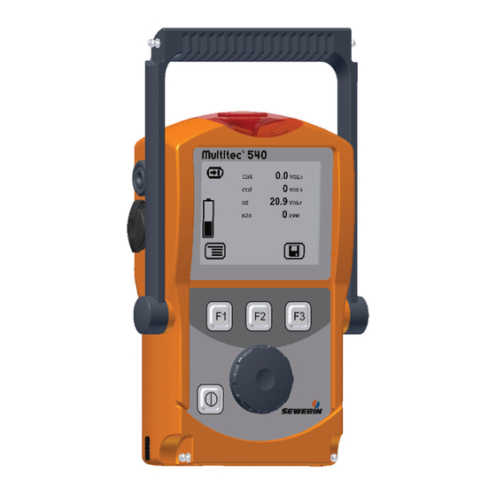
- Page 3 Buzzer Gas input USB port Display Function keys Jog dial ON/OFF key Connection for power supply Connector Fig. 1: Multitec 540 device overview Measured Unit value Gas measuring symbol Capacity of dis- posable battery/ rechargeable battery Current assignment of function keys F1 – F3 Fig.
- Page 4 Display symbols Menu Battery capacity Cancel Perform device inspection (jump to next input field) Save Open stored comment/inspector Information Clear Fault Measure gas...
- Page 5 Operating Instructions Multitec® 540 01.08.2011 – V1.XXX – 105832 – en...
- Page 6 Symbols used CAUTION! Danger of injuries! This symbol refers to important safety instructions. Adhere strictly to these instructions to avoid inju- ries! CAUTION! Danger of damages! This symbol refers to important safety instructions. Adhere strictly to these instructions to avoid mate- rial damages! Note: This symbol refers to information and useful tips which...
-
Page 7: Table Of Contents
Contents Page General ..................1 Warranty ...................1 Purpose ..................2 Intended use ................3 General safety information ............4 Features ...................5 Visual and audible signals ............5 Sensors ..................5 Explosion protection ..............6 Operation .................7 General information on operation ..........7 3.1.1 Keys and jog dial ..............7 3.1.2 Selecting / exiting menus and menu items ......8 3.1.3... - Page 8 Contents Page 4.2.2 Rechargeable battery servicing ..........22 Battery alarm ................22 Replacing disposable/rechargeable batteries ......23 Maintenance ................24 Device inspection ..............24 5.1.1 General information on the device inspection ......24 5.1.1.1 Scope ................24 5.1.1.2 Frequency .................24 5.1.1.3 Documentation ..............24 5.1.1.4 Integrated device inspection ..........25 5.1.1.5 Sequence ................26 5.1.2...
- Page 9 Contents Page Memory capacity ..............40 Sensors ...................41 7.4.1 Infra red sensors (IR) ............41 7.4.1.1 Methane CH ..............41 7.4.1.2 Carbon dioxide CO ............41 7.4.2 Electrochemical sensors (EC) ..........42 7.4.2.1 Oxygen O ................42 7.4.2.2 Hydrogen sulphide H S .............42 Technical information ..............43 7.5.1 Identification sticker (back of device) ........43 7.5.2...
-
Page 10: General
Hermann Sewerin GmbH cannot be held responsible for any dam- ages resulting from non-compliance with these instructions. The warranty and liability provisions of the terms of sale and delivery of Hermann Sewerin GmbH are not affected by the information given below. -
Page 11: Purpose
1 General Purpose The Multitec 540 is a gas measuring device for monitoring gas mixtures that are formed in biological processes (biogas, landfill gas). It measures the concentration of several gases in the gas mixture simultaneously. The device is ideal for use in waste dis- posal sites, sewage plants and biogas plants. -
Page 12: Intended Use
1 General Intended use This device is intended for professional residential and commercial use including small firms and commercial operations. The appro- priate specialist knowledge is required to operate the device. The device may be used to measure the following gases (depend- ing on the sensors fitted). -
Page 13: General Safety Information
1 General General safety information z The Multitec 540 is a gas measuring device as opposed to a gas warning instrument. It does not, therefore, warn of danger- ous toxic and explosive gas concentrations or lack of oxygen. If you suspect dangerous gas concentrations, always take along a gas warning instrument too. -
Page 14: Features
2 Features Features Visual and audible signals The device features two alarms: z Signal light on top of device (visual signal) z Buzzer on side of device (audible signal) The signals indicate faults (see Section 6). The device also emits signals when it is switched on and off. -
Page 15: Explosion Protection
2 Features Explosion protection The device features the following explosion protection: Explosion-proof For the following at- When using group mospheres II2G Ex d e ib IIB T4 Gb – Methane CH Device with- – Propane C out TG8 car- – Butane C rying bag –... -
Page 16: Operation
3 Operation Operation General information on operation 3.1.1 Keys and jog dial The ON/OFF key is the only control on the device that does not change its function. When switched on, the device is operated using the jog dial and function keys to navigate the display. -
Page 17: Selecting / Exiting Menus And Menu Items
3 Operation 3.1.2 Selecting / exiting menus and menu items Functions and settings etc. are selected via the main menu (for short: menu). This menu has submenus and menu items. Refer to Section 3.2.1 for information on accessing the main menu. Selecting submenus / menu items Submenus and menu items are selected and opened using the jog dial and/or the function keys (see Section 3.1.1). - Page 18 3 Operation Display: – Device type: Multitec 540 – User: Frank Smith City council – Firmware version: V1.000 – Date and time Fig. 3: Start screen An overview of the gases that can be detected will then appear briefly. Display: –...
-
Page 19: Differences Between Measuring Mode And Settings Mode
3 Operation 3.1.4 Differences between measuring mode and settings mode The device is operated in two modes: z Measuring mode (see Section 3.2) Measurements are taken in measuring mode. All functions needed to take readings can be accessed from one menu. z Settings (see Section 3.3) The device settings can be changed in settings mode. -
Page 20: Measuring Mode
3 Operation Measuring mode When switched on (see Section 3.1.3), the device is in measuring mode. In measuring mode, the current measurements are always displayed (see Fig. 5). 3.2.1 Accessing the menu (measuring mode menu structure) In measuring mode the menu can be accessed with F1. Zero point Gas measuring Settings... -
Page 21: Gas Measuring
Saving a measurement The current measurement values are saved using Save measu- rement. Measurement files can be displayed on a computer using a readout program. The program is available at www.sewerin.com. z Press Menu. z Select Save measurement from the menu. Note: If the current measurement values are stable, the Save symbol will appear. -
Page 22: Protocols
3 Operation z If necessary, enter a comment on the measurement. − Select the characters required using the jog dial. Confirm each character using the jog dial. − Press Open saved comment. A list of the saved comments will appear. Select the desired comment. Open the comment with OK. -
Page 23: Device Inspection
3 Operation 3.2.7 Device inspection Device inspection only appears in the menu when the integrated device inspection is switched on. The device inspection can be used to check the general status and the indication accuracies. Note: The integrated device inspection is switched off in the factory settings. -
Page 24: Settings
3 Operation Settings The following menus and menu items are included under Settings (see Sections 3.3.3 to 3.3.6): z Adjustment z System z Date/time z Memory You can find information on selecting and exiting menus and menu items in Section 3.1.2. 3.3.1 Opening Settings z Press Menu. -
Page 25: Settings Menu Structure
Device inspection Reset Language Exit Date/time Memory Clear Interval Memory mode Exit Exit Measuring mode Multitec 540 Settings menu structure Fig. 8: Note: The number and names of available menu items depend on the device model and optional additional equipment. -
Page 26: Adjustment
3 Operation 3.3.3 Adjustment The Adjustment menu is used to set the sensors. WARNING! The device must only be adjusted by specialist technicians in well ventilated rooms or in the open air. Incorrect adjustment can lead to incorrect meas- urement results. More detailed information about adjustment can be found in Sec- tion 5.2. -
Page 27: System
If the PIN code is set to 0000, you will not be asked to enter the PIN code. The settings can then be ac- cessed by anyone. If you lose the PIN code, you must contact SEWERIN Service. Service interval Specify the regular inspections/maintenance required for the de- vice. -
Page 28: Date/Time
3 Operation Device inspection Switches the integrated device inspection on and off. Reset Use to reset the device settings to the factory settings. Language Sets the language. 3.3.5 Date/time Used to set the time, day, month, and year. There are two formats available for the date. -
Page 29: Power Supply
/6/, only the following disposable/recharge- able batteries may be used: – Batteries supplied by SEWERIN – Others offered by SEWERIN, provided observ- ance as per /3/ is guaranteed. The battery types used in one battery compartment must always be identical in terms of sort (disposable/ rechargeable), capacity and manufacturer. -
Page 30: Operation With Rechargeable Batteries
4 Power supply Rechargeable battery requirements z NiMH rechargeable batteries z Battery size: AA, Type: HR6 as per /5/ z The creepage distance and air gap between the poles must not be less than 0.5 mm in accordance with /3/. z The rechargeable batteries must be fast charging (I >... -
Page 31: Rechargeable Battery Servicing
4 Power supply z Short operating times and long periods out of use can reduce the available battery capacity (memory effect). 4.2.2 Rechargeable battery servicing If the device is not used for a long period of time, it is recommend- ed to fully discharge the battery before recharging it again. -
Page 32: Replacing Disposable/Rechargeable Batteries
4 Power supply Replacing disposable/rechargeable batteries WARNING! Disposable/rechargeable batteries must always be replaced outside of the explosive area. A 2.5 mm Allen key (supplied) is required to open the battery compartment on the back of the device. z Loosen the two screws securing the battery compartment. Remove the screws by repeatedly turning each one a short distance in alternation;... -
Page 33: Maintenance
5 Maintenance Maintenance In accordance with the legal regulations, device maintenance comprises the following elements: z Device inspection including test of indication accuracy z Adjustment z Servicing All inspections must be documented. The documentation must be retained for at least one year. Device inspection 5.1.1 General information on the device inspection... -
Page 34: Integrated Device Inspection
5 Maintenance Only the integrated device inspection is described in these op- erating instructions. Note: The device inspection must be documented on pa- per if the integrated device inspection is switched off. 5.1.1.4 Integrated device inspection Note: The integrated device inspection is switched off in the factory settings. -
Page 35: Sequence
5 Maintenance 5.1.1.5 Sequence You can carry out the tests that make up the device inspection in any order you wish. You can repeat the tests as often as you wish provided you have not yet concluded the device inspection. 5.1.2 Performing the device inspection 5.1.2.1 Accessing the device inspection... -
Page 36: Concluding The Device Inspection
5 Maintenance z Carry out the test. For detailed information, refer to the following sections: − General Status Section 5.1.3 − Fresh air Section 5.1.4 − Test gas … Section 5.1.5 5.1.2.2 Concluding the device inspection After all the tests have been carried out as described in Sec- tions 5.1.3 to 5.1.5, the Save symbol will appear in the display. - Page 37 5 Maintenance Note: If you do not need to enter an inspector or a pass- word, these input fields can be skipped by press- ing Esc. The device inspection is still saved as a protocol. The device inspection protocols can be opened at any time (see Section 3.2.6).
-
Page 38: Testing The General Status
5 Maintenance 5.1.3 Testing the general status The general status test is part of the device inspection (see Sec- tion 5.1.1.1). It is based on estimations by the user. The following must be tested: z Housing z Signals z Probe z Filter z Pump The battery charge status and the working condition of the com-... -
Page 39: Filter
This indicates that the pump is working correctly. If the error message does not appear, the pump may be faulty. The device must be tested by SEWERIN Service. z Release the gas input again. After approximately seconds, the error message should disap-... -
Page 40: Testing Indication Accuracy With Supply Of Fresh Air
5 Maintenance 5.1.4 Testing indication accuracy with supply of fresh air The indication accuracy with supply of fresh air test is part of the device inspection (see Section 5.1.1.1). Ensure that the fresh air used for testing is sufficiently pure. z Select Fresh air from the Device inspection menu. - Page 41 5 Maintenance Cause Corrective action Connections leaking Repeat check, checking for the seal on the connections Measurement values outside Adjustment required the specified limit values (see Section 5.2) (see Section 7.2) Note: The Test gas OK message only appears when all the test gases specified in the device inspection have been successfully tested.
-
Page 42: Adjustment
5 Maintenance Adjustment WARNING! The device must only be adjusted by specialist technicians in well ventilated rooms or in the open air. Incorrect adjustment can lead to incorrect meas- urement results. 5.2.1 Scope The following are adjusted: z Zero point z Measuring range sensitivity CAUTION! Always adjust the zero point first, followed by the... -
Page 43: Adjusting The Zero Point
5 Maintenance You can access detailed information on the adjust- ment of the various gases (for example, test gas, installation date of the sensor, or date of the last ad- justment) under Information. This symbol appears after the respective Adjust- ment …... -
Page 44: Carrying Out Oxygen Adjustment
5 Maintenance z Connect the device to the test set. To do so, follow the steps indicated in the test set operating instructions. z Select the desired adjustment from the Adjustment menu (for example, CH4 adjustment). z Select the menu item that specifies the sensitivity to be tested (for example, 100 % VOL CH4). -
Page 45: Adjusting The Sensitivity For Oxygen
5 Maintenance z Press OK to confirm. The device is adjusted. The reading shows zero (0.0 % vol.). z Let go of the release button on the test set. 5.2.4.2 Adjusting the sensitivity for oxygen The sensitivity of oxygen is adjusted with fresh air. z Select Adjustment O2 from the Adjustment menu. -
Page 46: Servicing
5 Maintenance Servicing The device must only be serviced and repaired by SEWERIN Service. z Send the device to SEWERIN for repairs and for annual main- tenance. Note: If there is a service agreement in place, the device can be serviced by the mobile maintenance serv- ice. -
Page 47: Faults
IR sensor adjustment required (see Section 5.2) Adjustment failed Check test gas Test gas XFLASH Error can only be corrected by SEWERIN Service SEWERIN Service Error unknown Error can only be corrected by SEWERIN Service SEWERIN Service IR sensor Error can only be corrected by... -
Page 48: Appendix
7 Appendix Appendix Specifications and permitted operating conditions Dimensions Approx. 148 × 57 × 205 mm (W × D × H): Approx. 148 × 57 × 253 mm with supporting bracket Weight Approx. 1000 g, depending on equipment Operating position: Protection rating IP54 Power supply:... -
Page 49: Limit Values For The Device Inspection
7 Appendix Limit values for the device inspection Zero point Sensitivity Specification Deviation Specification Deviation 0.00 % vol. ±2 % vol. 100 % vol. ±5 % vol. 0 % vol. ±2 % vol. 100 % vol. ±5 % vol. 0 % vol. ±0.5 % vol. -
Page 50: Sensors
7 Appendix Sensors Note: Probes increase the stated response times. 7.4.1 Infra red sensors (IR) 7.4.1.1 Methane CH Type: Infrared sensor Measuring range: 0 – 100 % vol. Measuring error CH ±1.5 % vol. Response times: < 9 s < 17 s Temperature range: -20 ºC –... -
Page 51: Electrochemical Sensors (Ec)
7 Appendix 7.4.2 Electrochemical sensors (EC) 7.4.2.1 Oxygen O Type: Electrochemical sensor Measuring range: 0 – 25 % vol. Resolution: 0.1 % vol. Measuring error: ±3 % or ±0.3. % vol. (±3 digits) Response time: < 15 s Drift: < 2 % within 3 months Temperature range: -20 ºC –... -
Page 52: Technical Information
7 Appendix Technical information 7.5.1 Identification sticker (back of device) The symbols on the sticker mean the following: Always open battery compartment outside the explosive area. Read the operating instructions. 7.5.2 Cleaning The device must only be cleaned with a damp cloth. CAUTION! Do not use solvents, petrol or cockpit spray con- taining silicone or similar substances to clean the... -
Page 53: Accessories
7 Appendix Accessories: Docking station TG8 Art. no.: LP11-10001 z For charging, operating and holding one device z Includes locking mechanism to prevent unit falling out z AC/DC adapter or vehicle ca- ble required for charging and operation AC/DC adapter M4 Art. - Page 54 7 Appendix Vehicle cable M4 Art. no.: ZL09-10000 z 24 V= mounting, includes volt- age converter and female spade converters z permanently connects unit to the vehicle electrical system Carrying system "Vario" Art. no.: 3209-0012 z Two adjustable carrying straps with quick release buttons and padded straps z Can be worn around the neck...
- Page 55 Art. no.: ZD29-10000 z With built-in compartments z Allows for charging from the outside z Holds: – Multitec 540 – Docking station TG8 – AC/DC adapter M4 – Probe hose 1 m, 2 m or 6 m – Flexible handheld probe –...
- Page 56 7 Appendix Flexible handheld probe Art. no.: ZS32-10000 z 360 mm long z Flexible tip with handle for leak detection in two-handed operation z Probe hose 1 m required Probe hose Art. no.: ZS25-10000 (example) z With hydrophobic filter and quick connects z Various lengths available Gas sample connection...
- Page 57 % vol. range and for test- ing the pump capacity z Includes connection for all SEWERIN test gas cans z Manometer (0 – 16 bar) for displaying the test gas can p r e s s u r e a n d f l o w m e t e r (0 –...
- Page 58 7 Appendix Rechargeable NiMH battery Art. no.: 1354-0009 z AA, HR6, 1.2 V 2700 mAh Disposable alkaline battery Art. no.: 1353-0001 z AA, LR6, 1.5 V Other accessories are available for the device. Please contact our sales department for further information.
-
Page 59: Declaration Of Conformity
When the carrying bag for the accessories is used, the following explosion-proof group applies: − II2G Ex d e ib IIC T4 Gb EC type-examination certificate: − TÜV 07 ATEX 553353 X Gütersloh, 2011-08-01 Dr. S. Sewerin (CEO) The complete declaration of conformity can be found online. -
Page 60: Inspection Protocol
7 Appendix Inspection protocol INSPECTION PROTOCOL Multitec® 540 Fab. no. (e.g.: 066 11 0501) 01.07.2009 1.0 General Status 1.1 - Housing correct (e.g.: Y / N) 1.2 - Fine dust filter correct (e.g.: Y / N) 1.3 - Battery capacity (e.g.: ¼) 2.0 Pump check 2.1 - Pump error F100 in seal 3.0 Methane CH... -
Page 61: Advice On Disposal
Test gas can 16 05 05 Disposable battery, 16 06 05 rechargeable battery End-of-life equipment Used equipment can be returned to Hermann Sewerin GmbH. We will arrange for the equipment to be disposed of appropriately by certified specialist contractors free of charge. -
Page 62: Terminology And Abbreviations
7 Appendix 7.10 Terminology and abbreviations CENELEC z European Committee for Electrotechnical Standardisation z Electrochemical sensor Gas type z Hydrocarbon C which can be meas- ured with the IR z Infrared sensor NiMH z Nickel metal hydride z Parts per million Ring memory z Type of data storage in the device z If the available storage space is full, the... -
Page 63: Referenced Documents
7 Appendix 7.11 Referenced documents The following standards, guidelines and regulations are referred to in these operating instructions: Bundesverband der landwirtschaftlichen Berufsgenossenschaften e. V. (Federal Association of Institutions for Statutory Accident Insur- ance and Prevention in the Agricultural Sector): Safety regulations for agricultural biogas plants (Procedure Document 69) For reference consult regional agricultural employer's liability insur- ance association... -
Page 64: Index
8 Index Index Display contrast 18 Display illumination 18 Accessories: 44 Disposal 52 Adjustment 17, 33 C02 17 CH4 17 Of oxygen 35 Electrostatic charge 43 Performing 33 Error message 38 Preparation 33 Explosion protection 6 Scope 33 Sensitivity 34 Zero point 34 Factory settings 19 Adjustment menu 17... - Page 65 8 Index Infrared~ 5, 41 Installation date 14 Main menu see Menu Service interval 18 Maintenance 24 Servicing 37 Measurement Settings 10, 12, 15 Save 12 Menu structure 16 Starting 12 Opening 15 Stopping 12 Signals 29 Measuring mode 10, 11 Audible 5 Menu structure 11 Visual 5...
- Page 66 Hermann Sewerin GmbH Robert-Bosch-Straße 3 · 33334 Gütersloh · Germany Telefon +49 5241 934-0 · Telefax +49 5241 934-444 www.sewerin.com · info@sewerin.com...
Need help?
Do you have a question about the Multitec 540 and is the answer not in the manual?
Questions and answers