Table of Contents
Advertisement
Quick Links
Advertisement
Table of Contents

Subscribe to Our Youtube Channel
Related Manuals for sewerin EX-TEC PM 4


Summary of Contents for sewerin EX-TEC PM 4
- Page 1 Operating Instructions...
- Page 2 Measurable success by Sewerin equipment Congratulations. You have chosen a quality instrument manufactured by Hermann Sewerin GmbH. Our equipment will provide you with the highest standards of perfor- mance, safety and efficiency. They correspond with the national and international guide-lines.
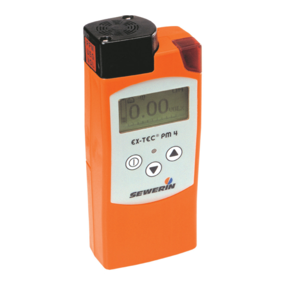
- Page 3 Illustration EX-TEC PM 4 Overview of device Sensor head Suspension fitting Alarm light Buzzer LCD matrix Keypad Battery charge contacts Liquid Crystal Display Gas type Alarm threshold Case / operating activation mode Gas concentration Unit of measure Battery status Trend bar...
- Page 4 Overview Control keys Device On/Off (press and hold for approx. 3 seconds) Used to enter / confirm selection (press briefly) Used to switch between applications / menu item selections Press and hold one key for 2 seconds: accesses user menu Press and hold both keys for 2 seconds: accesses advanced settings Symbols on LCD...
- Page 5 Operating Instructions EX-TEC PM 4 ® 20.04.2016 – V2.XXX – 105806 – en...
- Page 6 Symbols used CAUTION! Danger of injuries! This symbol refers to important safety instructions. Adhere strictly to these instructions to avoid inju- ries! CAUTION! Danger of damages! This symbol refers to important safety instructions. Adhere strictly to these instructions to avoid mate- rial damages! Note: This symbol refers to information and useful tips which...
-
Page 7: Table Of Contents
Contents Page General ..................1 Warranty ..................1 Purpose ..................2 Intended use ................2 General safety information ............3 Features ...................5 Visual signals and audible signals ..........5 Measurement principles ............6 Explosion protection ..............7 Operation .................9 General information on operation ..........9 3.1.1 Operator guidance ..............9 3.1.2 Operating modes ..............10 Measuring mode .............. - Page 8 Contents Page Charging and battery operation ...........43 General information on charging and battery operation ..43 4.1.1 Suitable types of rechargeable and disposable batteries ..43 4.1.1.1 Devices with serial numbers 060 0X and 061 0X....43 4.1.1.2 Devices with serial numbers 060 1X and 061 1X....44 4.1.2 Setting the rechargeable / disposable battery type ....45 Battery alarm ................45...
- Page 9 Contents Page Available models and accessories ........69 Available models ..............69 Accessories ................70 Appendix ....................75 Gas types ....................75 Setting ranges for test gases ..............79 Test certificates ..................80 EU declaration of Conformity..............81 Entering a user name ................84 List of abbreviations................86 Index ......................87...
-
Page 10: General
Hermann Sewerin GmbH cannot be held responsible for any dam- ages resulting from non-compliance with these instructions. The warranty and liability provisions of the terms of sale and delivery of Hermann Sewerin GmbH are not affected by the information given below. -
Page 11: Purpose
1 General Purpose The EX-TEC PM 4 is an electronic handheld device for the de- tection and measurement of gas concentrations. Equipped with three sensors, it can be used for the ppm range, the % vol. range and the LEL range. -
Page 12: General Safety Information
1 General General safety information z The EX-TEC PM 4 has been tested to ensure that it is explosion- proof in accordance with European standards (CENELEC). z The functional safety of the EX-TEC PM 4 has been tested in the LEL range, Warning (%LEL) application, for gas types... - Page 13 1 General WARNING! Follow the advice regarding explosion protection (see Section 2.3). z When the Warning %LEL application is in use, a brief audi- ble signal emitted every 5 seconds indicates that the device is working properly. If no operating signal sounds, there is no guarantee that the gas concentration is being monitored.
-
Page 14: Features
2 Features Features The EX-TEC PM 4 is available in two models (see Section 8.1): z Diffusion device: basic device without a pump z Pump device: basic device with an integrated pump (designation on back of device: P) The EX-TEC PM 4 is suitable for the following applications: –... -
Page 15: Measurement Principles
2 Features Measurement principles The device features three sensors: Semiconductor sensor Measuring range 0 to 10,000 ppm Application House Enclosed spaces Catalytic combustion sensor Measuring range 0 to 100 % LEL Application Warning %LEL Thermal conductivity sensor Measuring range 0 to 100 % vol. Application Measuring vol% House... -
Page 16: Explosion Protection
2 Features Explosion protection The EX-TEC PM 4 features the following explosion-protection classifications: II2G Ex d e ib IIB T4 Gb Basic device without leather bag for: – Methane CH – Propane C – Butane C – Hexane C – Nonane C –... - Page 17 2 Features WARNING! It is essential to observe the following points to en- sure that the device is explosion-proof: – Always open the battery compartment outside the potentially explosive area. – Always recharge the batteries outside the poten- tially explosive area. –...
-
Page 18: Operation
Operation General information on operation 3.1.1 Operator guidance There are two ways to operate the EX-TEC PM 4: – Operator guidance by application – Operator guidance by sensor These operating instructions are based on operator guidance by application in accordance with DVGW Note G 465-4: –... -
Page 19: Operating Modes
3 Operation 3.1.2 Operating modes The device is operated in two modes: z Measuring mode (Section 3.2) Measurements are taken in measuring mode. The zero point can be set, the application can be changed and the gas type can be selected via the user menu. z Advanced settings (Section 3.3) The advanced settings allow you to change specifications for the measurements as well as other device settings (e.g. -
Page 20: Measuring Mode
3 Operation Measuring mode The device is switched off. Note: Always switch the device on in fresh air. z Press the key for approximately 3 seconds. The device switches on. At this point, the two signalling mecha- nisms are always tested. WARNING! Do not use the device if you do not see the visual signal and hear the audible signal briefly when... - Page 21 3 Operation The device accesses the preset application. Two additional screens are displayed automatically. Note: The start-up application can be changed in the ad- vanced settings (see Section 3.3.4.3). The factory default setting for the device is the Warning %LEL application.
- Page 22 3 Operation z Warning %LEL Measuring range Name of application with specifi- cation of measurement unit Measurement data Measurement data display z Measuring VOL% Measuring range Name of application with specifi- cation of measurement unit Measurement data Measurement data display You cannot input any information until the device has stopped cycling through the displays.
-
Page 23: User Menu
3 Operation 3.2.1 User menu Measuring mode comprises the following functional scope: – Zero point correction – Application selection – Confirmation of function control – Gas type (optional) The functions in the user menu are described in Sections 3.2.2 to 3.2.8. To select functions, you must first access the user menu: z Press the key or the... -
Page 24: Setting The Zero Point
3 Operation 3.2.2 Setting the zero point In general, the device sets the zero point automatically. However, in certain cases, values other than zero may be displayed when the device is switched on. This indicates a deviating zero point, meaning that the device must be adjusted manually to environ- mental conditions. -
Page 25: House Application
3 Operation 3.2.3 House application The House application is used to measure minute gas concentra- tions in buildings and to locate the origin of the gas. Measurement unit: ppm (parts per million) % vol. Measuring range: Semiconductor 0 to 10,000 ppm Thermal conductivity 1 to 100 % vol. - Page 26 3 Operation Procedure: z Press the key or the key for approximately 2 seconds to access the user menu. z Use the key to select the House menu item. z Confirm your selection with the key. Following confirmation, the start screen for the House application is displayed initially.
-
Page 27: Enclosed Spaces Application
3 Operation 3.2.4 Enclosed spaces application The Enclosed spaces application is used to measure gas con- centrations in enclosed spaces where there is increased potential of gas dispersal. Measurement unit: ppm (parts per million) % vol. Measuring range: Semiconductor 0 to 10,000 ppm Thermal conductivity 0.1 to 100 % vol. - Page 28 3 Operation Procedure: z Press the key or the key for approximately 2 seconds to access the user menu. z Use the key to select the Enclosed spaces menu item. z Confirm your selection with the key. Following confirmation, the start screen for the Enclosed spaces application is displayed initially.
-
Page 29: Warning %Lel Application
3 Operation 3.2.5 Warning %LEL application The Warning %LEL application is used to test working environ- ments where explosion is possible, e.g. working on gas pipes or gas systems. Measurement unit: % LEL Measuring range: Catalytic combustion 1 % LEL to 100 % LEL In the Warning %LEL application, a brief audible signal emitted every 5 seconds indicates that the device is working properly. - Page 30 0.00 % vol. As a trend bar divided into 10 parts ranging from 0 % LEL to 100 % LEL in increments of 10 %. For the Warning %LEL application, the EX-TEC PM 4 features three alarm thresholds. Alarm thresholds z Alarm threshold 1 (AL1 –...
- Page 31 3 Operation z Alarm threshold 3 (AL3 – continuous alarm and end of meas- uring range): – When this alarm threshold is exceeded, a continuous audible alarm and a continuous visual alarm are triggered and AL3 flashes on the display. –...
-
Page 32: Measuring Vol% Application
3 Operation 3.2.6 Measuring VOL% application The Measuring VOL% application is used to demonstrate gas purity or the absence of gas in gas pipes. WARNING! The Measuring VOL% application is not suitable for use in hazardous areas. It does not comprise an alarm mechanism. - Page 33 3 Operation Following confirmation, the start screen for the Measuring VOL% application is displayed initially. Measuring range Then the device returns to measuring mode. The measured val- ues are displayed. Measurement data In number format: e.g. 0 % vol. As a trend bar divided into 10 parts from 0 % vol. to 100 % vol. in increments of 10 %.
-
Page 34: Function Control
3 Operation 3.2.7 Function control Before starting work and when resuming work after an interruption, you must carry out a function control. The scope of the function control is described in Section 5.1. Confirm the successful completion of the control on the device as follows: z Press the key or the... -
Page 35: Changing Gas Types
3 Operation 3.2.8 Changing gas types Note: Always change the gas type in fresh air. Only calibrated gas types can be selected in the user menu. The factory default setting for the device is methane CH (or a special gas you have ordered). z Press the key or the key for approximately 2 seconds. -
Page 36: Advanced Settings
3 Operation Advanced settings Settings for the following areas of the device can be made in the advanced settings: z Adjustment z System z Hardware z Memory You cannot perform measurements in the advanced settings. 3.3.1 Access There are two ways to access the Advanced settings area: The device is switched off: z Simultaneously press the keys for approximately... - Page 37 If you cannot access the Advanced settings area, for example, if you have lost the PIN code, you must contact SEWERIN Service. Enter the PIN code from left to right. The active digit is always displayed with a black background: z Use the key to select the first digit.
-
Page 38: Menu Structure
3 Operation 3.3.2 Menu structure Menu level 1 Menu level 2 Measuring mode Info V2.000 PIN code adjustment 0 PPM 10000 PPM 0 %LEL 50 %LEL 100 VOL% inspection ok exit system date / time date format INS interval INS block PPM signal PIN code AL1 alarm... -
Page 39: Procedure
3 Operation 3.3.3 Procedure The advanced settings are divided into three menu levels. z The first two menu levels are used to organise and subdivide the settings options. z A concrete selection or entry is made in the third menu level. The name of the current menu (e.g. - Page 40 3 Operation Menu level 3 Menu level 3 is used to select settings or enter values: z Selecting settings Use the keys to navigate within a selection. Press the key to confirm the selected setting. When you have confirmed your selection, the display reverts to the previous menu.
-
Page 41: Info Menu
3 Operation 3.3.4 Info menu The Info menu is located at the top of the Advanced settings: adjustment system hardware memory exit Note: When you select Exit from the Info menu, the de- vice returns to measuring mode. 3.3.4.1 Adjustment menu The Adjustment menu is used to set the sensors. -
Page 42: 3.3.4.2 System Menu
3 Operation 3.3.4.2 System menu General information and specifications for operation, inspection and alarms are set on the System menu. system date/time date format INS interval INS block PPM signal PIN code AL1 alarm AL2 alarm AL4 alarm AL5 alarm test gas PPM test gas %LEL unit %LEL... - Page 43 3 Operation INS block When the inspection block is enabled, an inspection must be performed on the next due date. The device cannot be used in measuring mode until the inspec- tion has been carried out and confirmed. PPM signal acoustic /LED acoustic Used to switch visual/audible...
- Page 44 3 Operation AL5 alarm VOL% 100 Permanently assigned alarm threshold for the Measur- ing VOL% application. Indicates the end of the measur- ing range. 1.00 Vol% Test gas PPM 2.20 Vol% Used to set the test gas con- centration for the ppm range based on the gas type.
- Page 45 3 Operation Unit VOL% VOL% %VOL Used to set individual measured variables for the VOL range %GAZ (Measuring VOL% application). %OBJ tf.% User name City Council Frank Smith Used to enter the user name. This is important for document- Leakage Delivery ing the measurements.
- Page 46 3 Operation For operator guidance by sensor, the user menu looks like this: zero point 0..10000 PPM 0..100 %LEL 0..100 VOL% automatic inspection ok type of gas Language Deutsch English The device can be operated in 13 different languages. Français Italiano Dansk Cesky...
-
Page 47: 3.3.4.3 Hardware Menu
3 Operation 3.3.4.3 Hardware menu The Hardware menu comprises settings pertaining to device management. hardware battery Accu capacity back light contrast sensors type of gas autostart level PPM pump LCD test reset exit Battery Accu Ni-MH Used to set the battery type in Alcaline use. - Page 48 Contrast settings to facilitate reading of the LCD (in approxi- mately 30 increments). Sensors CAUTION! Settings in the Sensors menu item may only be configured by SEWERIN Service! Gas type C3H8 Used to permanently change the measuring medium. C4H10 C6H14...
- Page 49 3 Operation Autostart House Enclosed spaces Use to set the test type that is activated when the device is Warning %LEL switched on. Measuring vol% For operator guidance by sen- sor, the autostart menu looks like this: 0..10000 PPM 0..100 %LEL 0..100 VOL% automatic PPM 001...
-
Page 50: 3.3.4.4 Memory Menu
3 Operation 3.3.4.4 Memory menu The Memory menu enables you to delete the recorded measure- ments, function controls and alarms. All other settings remain unchanged. memory clear interval exit Clear Used to clear the contents of the memory. Interval 30 Sec The frequency with which read- ings are to be saved can be set according to the table below. -
Page 51: Connecting Accessory Devices
3 Operation Connecting accessory devices The following accessory devices can be fitted to the sensor head: z Probes For detection and measurement in hard-to-reach places. Probes are fitted using two knurled thumb screws. z Test head For adjusting the device using a test set. Note: Certain probe types can only be used with devices having an integrated pump. -
Page 52: Charging And Battery Operation
4 Charging and battery operation Charging and battery operation General information on charging and battery operation WARNING! The device must not be used with leaking dispos- able / rechargeable batteries. Replace disposable / re- chargeable batteries in a timely manner. Clean the bat- tery compartment (and, if necessary, the device) before inserting the new disposable / rechargeable batteries. -
Page 53: 4.1.1.2 Devices With Serial Numbers 060 1X And 061 1X
/ rechargeable batteries may be used: – Batteries supplied by SEWERIN – Batteries other than those supplied by SEWERIN, provided they comply with standard EN 60079-7:2003 (in particular Section 5.7.2.1.17; explanation below) The battery types used in a battery compartment must always be identical in terms of sort (dispos- able / rechargeable), capacity and manufacturer. -
Page 54: Setting The Rechargeable / Disposable Battery Type
4 Charging and battery operation 4.1.2 Setting the rechargeable / disposable battery type To ensure that the charging time and remaining battery life are properly displayed, you must specify the following in the advanced settings: z Rechargeable battery type (Info menu – Hardware – Battery) z Capacity of rechargeable types in use (Info menu –... -
Page 55: Operation With Nickel Metal Hydride Rechargeable Batteries (Nimh)
4 Charging and battery operation Operation with nickel metal hydride rechargeable batteries (NiMH) The docking station HG4 is required for charging. The docking station can be used in the workshop or in the service vehicle. CAUTION! Compliance with the following guidelines is essential to ensure trouble-free operation: z The docking station must not be directly connected to a 24-V on-board power supply in the vehicle. - Page 56 4 Charging and battery operation Charging: z Place the device (switched off) into the docking station. The time required for complete charging is displayed. Once the rechargeable batteries have been fully charged, the device automatically switches to charge maintenance mode. It can remain in the docking station until the next time it is used.
-
Page 57: Operation With Alkaline Non-Rechargeable Batteries
When equipped with new disposable alkaline batteries, the EX-TEC PM 4 has an available operating time of at least 12 hours (depending on the capacity of the accumulator used). Follow the steps below to change the batteries: z Using the supplied screwdriver, unscrew the bottom two screws on the back of the device. -
Page 58: Maintenance
5 Maintenance Maintenance In accordance with legal regulations, device maintenance com- prises the following elements: z Function control z Indication accuracy test z Adjustment z Servicing Note: As specified in EN 60079-29-2 / BGI T 023, port- able gas warning devices must be tested by the user immediately prior to each use. -
Page 59: Testing Indication Accuracy With Test Gas
5 Maintenance The frequency of the test depends on the application. For the Warning %LEL application, it must be carried out before com- mencing each work session! When the function control is complete, it can be stored in the user menu (see Section 3.2.7). - Page 60 (C) indicates the pressure inside the test gas canister. z Switch on the EX-TEC PM 4. z Wait until the EX-TEC PM 4 has finished warming up. z Press release button (D) to release the test gas. Keep the but- ton depressed.
-
Page 61: Adjustment
5 Maintenance Adjustment Both the zero point and the indication accuracy must be adjusted for each of the three sensors. WARNING! The device be adjusted by specialist technicians only. Incorrect adjustment can result in incorrect analysis of the measurement results. The Adjustment menu is shown in Section 3.3.4.1. -
Page 62: Ppm Range
5 Maintenance 5.3.1 ppm range CAUTION! Atmospheric humidity can cause interference in the semiconductor sensor. Therefore, never adjust the device without using conditioner fitted between the device and the test set! Tools: z Test head HG 4 z Test set with integrated conditioner (e.g. -
Page 63: Lel Range And % Vol. Range
5 Maintenance z Press and hold the release button on the test set until the con- centration displayed on the device has reached a stable value. z Press the On/Off key to confirm. 5.3.2 LEL range and % vol. range Tools: z Test head HG 4 z Test set (see Accessories) -
Page 64: Confirming Adjustment
The device must only be serviced and repaired by SEWERIN Service or a qualified service technician/company authorised by SEWERIN. z Send the device to SEWERIN for repairs and for annual main- tenance. Note: If there is a service agreement in place, the device can be serviced by the mobile maintenance service. -
Page 65: Pump
If the pump is functioning pro- perly, a corresponding error message will be displayed. Press any key to acknowledge the error message. If the error message does not appear, the pump may be faulty. Have the device tested by SEWERIN Service. -
Page 66: Changing The Pump Filter
5 Maintenance 5.5.2 Changing the pump filter CAUTION! Always switch off the device before changing the filter. z Unscrew and remove the sensor cap. z Take the sensor out of its holder. z Remove the pump filter (white disk, 4 mm in diameter). z Insert a new pump filter. -
Page 67: Faults
Measuring range Adjust LEL range RANGE violation in LEL range 51-54 ERROR Component error Switch device off and back UNKNOWN on or consult SEWERIN- Service VOLTAGE Voltage outside Error can only be corrected SUPPLY permissible range by SEWERIN Service ERROR... -
Page 68: Technical Data
7 Technical data Technical data Features z Gas types – Standard: Methane (CH – Optional: Propane (C Butane (C Hexane (C Nonane (C Kerosene (JFUEL) Hydrogen (H Acetylene (C z Liquid Crystal Display Graphic display, 65 × 132 pixels z Membrane keypad 3 keys z Buzzer Frequency 2.4 kHz... -
Page 69: Alarm Thresholds
7 Technical data Alarm thresholds 7.2.1 Alarm thresholds for gas type methane CH CAUTION! AL1 must always be set to a lower value than AL2. z House application Alarm Gas concentration Signal Setting range Factory Audible Visual setting 10 – 4,400 ppm Concentration- Concentration- dependent... - Page 70 7 Technical data z Warning application (Warning %LEL) Alarm Gas concentration Signal Setting range Factory Audible Visual setting 0 – 10 % LEL – – 10 – 50 % LEL 10 % LEL Pre-alarm 2 Hz Pre-alarm 2 Hz 10 – 60 % LEL 50 % LEL Main alarm Main alarm...
-
Page 71: Setting Ranges Of Alarm Thresholds For Different Gas Types
7 Technical data 7.2.2 Setting ranges of alarm thresholds for different gas types The factory settings are shown in bold. Gas type All (%LEL) Threshold 10 % LEL 50 % LEL Threshold 0.45 % vol. 2.20 % vol. Methane (CH Setting range 0.45 –... -
Page 72: Response Times
0.5 % vol. Automatic 100 % vol. Measuring Gas measuring Response times z Response times of EX-TEC PM 4 (pump devices) – ppm range: < 7 s for methane (CH < 7 s for propane (C < 7 s for butane (C <... -
Page 73: Sensors
7 Technical data z Response times of EX-TEC PM 4 (diffusion device without probe) – LEL range: < 8 s for methane (CH < 17 s for propane (C < 36 s for methane (CH < 74 s for propane (C <... -
Page 74: Ranges Of Use
7 Technical data Ranges of use z Operating temperature: -20 °C to +40 °C z Storage temperature: -25 °C to +55 °C z Humidity: 5 % r.h. to 90 % r.h. (non-condensing) z Pressure: 800 hPa to 1,200 hPa Pump capacity z Vacuum: >... -
Page 75: Technical Information
7 Technical data Technical information Identification sticker The pictogramme on the identification sticker (back of device) signifies that the battery must only be opened outside the poten- tially explosive area! Gas application / inerting Gas application (increasing concentration to 100 % vol.) and in- erting (decreasing concentration to 0 % vol.) must be carried out in the Measuring VOL% application. - Page 76 7 Technical data Cleaning The device must only be cleaned with a damp cloth. CAUTION! Do not use solvents, petrol or cockpit spray con- taining silicone or similar substances to clean the device! Static charging Electrostatic charging must generally be avoided. Electrostati- cally unearthed objects (e.g.
-
Page 77: Advice On Disposal
16 05 05 Disposable battery, 16 06 05 rechargeable battery End-of-life equipment End-of-life equipment can be returned to Hermann Sewerin GmbH. We will arrange for the equipment to be disposed of ap- propriately by certified specialist contractors free of charge. -
Page 78: Available Models And Accessories
8 Available models and accessories Available models and accessories Available models EX-TEC PM 4 – W Art. no.: PM04-20001 z Diffusion device for Warning application z Includes catalytic combustion sensor EX-TEC PM 4 – W/H/H/M Art. no.: PM04-20201 z Pump device for Warning,... -
Page 79: Accessories
8 Available models and accessories Accessories Docking station HG 4 Art. no.: LP10-10001 Docking station HG 4 with interface Art. no.: LP10-10101 AC/DC adapter M4 Art. no.: LD10-10001 Vehicle cable 12 V= mounting Art. no.: ZL07-10000 z For connecting docking station HG 4 to 12 V= vehicle electri- cal system z Includes built-in fuse and fe-... - Page 80 8 Available models and accessories Vehicle cable 24 V= mounting Art. no.: ZL09-10000 z For connecting docking station HG 4 to 24 V= vehicle electri- cal system z Includes voltage converter and female spade connectors for permanent connection Carrying bag HG 4 Art.
- Page 81 These probes are suitable for gas types methane CH propane C hydrogen H and acetylene C Probes for other gas types are available upon request. For Flex handheld probe HG4 and Flex probe HG4, use only SEWERIN-approved filters with acti- vated carbon.
- Page 82 For mobile use, including use in vehicles z I n c l u d e s c o n n e c t i o n f o r SEWERIN test gas cans, flow regulation, release button and connecting hose in conjunc-...
- Page 83 8 Available models and accessories Pressurised gas canisters z For testing and adjustment of indication accuracy z Various test can concentra- tions in 0.4- / 2.0- / 10.0-litre steel canisters pressurised to 100 – 150 bar Case HG4 Art. no.: ZD18-10000 z Holds: –...
-
Page 84: Appendix
Appendix Appendix Gas types LEL values are specified in accordance with IEC 60079-20. Methane CH (100 % LEL = 4.40 % vol.) Area of Test gas Tolerances / fresh Tolerances / test application air zero point gas indication accuracy 1.0 % vol. CH ppm range 0 ppm 0.8 to 1.4 % vol. - Page 85 Appendix Butane C (100 % LEL = 1.40 % vol.) Area of Test gas Tolerances / fresh Tolerances / test application air zero point gas indication accuracy ppm range Replacement test 0 ppm 0.8 to 1.4 % vol. gas 1.0 % vol. C in synth.
- Page 86 Appendix Kerosene JFUEL (100 % LEL = 0.70 % vol.) Area of Test gas Tolerances / fresh Tolerances / test application air zero point gas indication accuracy ppm range Replacement test 0 ppm 0.3 to 0.4 % vol. 0.30 % vol. C in synth.
- Page 87 Appendix Determining replacement test gas concentration using hexane adjustment as an example: z Replacement test gas (specified): 1.0 % vol. propane According to the table above, the display setpoint is 0.72 % vol. The test gas concentration must be set to 0.72 % vol. z Replacement test gas (alternative): 0.85 % vol.
-
Page 88: Setting Ranges For Test Gases
Appendix Setting ranges for test gases Gas type Test gas ppm Test gas% LEL 1.00 % vol. or 1.75 to 3.50 % vol Setting range 2.20 % vol. (40 to 80 % LEL) Methane (CH 0.05 % vol. Increment – (1 % LEL) 0.34 to 1.36 % vol Setting range... -
Page 89: Test Certificates
Appendix Test certificates Passive explosion protection The EX-TEC PM 4 has been tested to ensure that it is explosion- proof in accordance with European standards (CENELEC): EC type-examination certificate: TÜV 09 ATEX 555077 X Designation 1: II2G Ex d e ib IIB T4 Gb... -
Page 90: Eu Declaration Of Conformity
Appendix EU declaration of conformity Hermann Sewerin GmbH hereby declares that the EX-TEC PM 4 ® fulfils the requirements of the following guidelines: z 2014/34/EU z 2014/30/EU Gütersloh, 2016-04-20 Dr. S. Sewerin (General Manager) The complete declaration of conformity can be found online. - Page 91 Appendix ® EX-TEC PM 4 (methane CH Inspection protocol Sensor PPM — — VOL Serial no. (e.g. 060 10 0001) 16.07.2007 1.0 Device status 1.1 - status correct (e.g.: Y / N) 1.2 - remaining operating hours (e.g.: 5 h) 2.0 Pump test 2.1 - fault F100 when sealing 2.2 - pump filter changed (e.g.: Y / N)
- Page 92 Appendix ® EX-TEC PM 4 (propane C Inspection protocol Sensor PPM — — VOL Serial no. (e.g. 060 10 0001) 16.07.2007 1.0 Device status 1.1 - status correct (e.g.: Y / N) 1.2 - remaining operating hours (e.g.: 5 h) 2.0 Pump test 2.1 - fault F100 when sealing 2.2 - pump filter changed (e.g.: Y / N)
-
Page 93: Entering A User Name
Appendix Entering a user name The user name is stored in the advanced settings (System menu). The advanced settings are explained in Section 3.3. The procedure for accessing the advanced settings is provided in Section 3.3.1. Use the and the key to enter the characters. - Page 94 Appendix Case 2: An existing character is overwritten. When you move the cursor to this position, the existing character is highlighted with a black block. Press the key to display a space, then select the letters A – Z in ascending order. After the letter Z, the selection starts over with A.
-
Page 95: List Of Abbreviations
Appendix List of abbreviations CENELEC European Committee for Electrotechnical Stand- ardization DVGW Deutsche Vereinigung des Gas- und Wasserfaches e. V. (German Technical and Scientific Association for Gas and Water) Liquid Crystal Display NiMH Nickel metal hydride Parts per million TRGI Technical regulations for gas installations Lower Explosion Level Volume... -
Page 96: Index
Appendix Index Device charging 46 Accessories 70 features 5 Accessory devices 42 maintenance 49 Accu capacity 38, 45 on/off see Cover Adjustment 52 operation 9 confirming 55 Disposal 68 indication accuracy 53, 54 Docking station 46 zero point 53, 54 Adjustment menu 32 Advanced settings 27 AL1 alarm 34... - Page 97 Appendix Light 38 Tester 50 Test gas %LEL 35 Test gas PPM 35 Maintenance 49 Test head 42 Measurement principles 6 Thermal conductivity sensor 6 Measuring mode 11 Measuring VOL% application 23 Memory menu 41 Menu structure 29 Unit %LEL 35 Unit VOL% 36 User menu 14 User name 36...
- Page 98 Hermann Sewerin GmbH Robert-Bosch-Straße 3 · 33334 Gütersloh · Germany Telefon +49 5241 934-0 · Telefax +49 5241 934-444 www.sewerin.com · info@sewerin.com...
Need help?
Do you have a question about the EX-TEC PM 4 and is the answer not in the manual?
Questions and answers