Table of Contents
Advertisement
Quick Links
Advertisement
Table of Contents

Related Manuals for sewerin VARIOTEC 480 EX


Summary of Contents for sewerin VARIOTEC 480 EX
- Page 1 VARIOTEC 480/460/450/400 EX ® Operating instructions...
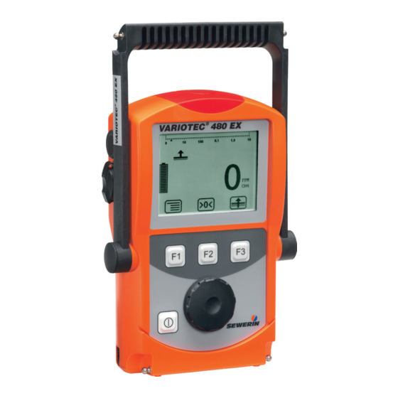
- Page 2 Supporting bracket Signal light Buzzer Gas input USB port Display Function keys Jog dial ON/OFF key Connection for Connector power supply VARIOTEC 480 EX device overview Fig. 1: Bar display Selected Measurement value application Alarm 0.90 Capacity Unit disposable battery/ VOL%...
- Page 3 Display symbols General Menu Fault Carry out device inspection Cancel (jump to next input field) Buzzer off Set zero point Take sample Purge Save Stop measurement Clear Information Capacity disposable Open stored comment battery/rechargeable Open stored inspector battery Applications Inspection above ground Gas measuring Measuring in bar holes Warning %LEL...
- Page 4 Information about this document The warnings and notes in the document mean the following: DANGER! Risk of personal injury. Results include serious injury or death. WARNING! Risk of personal injury. Can result in serious injury or death. CAUTION! Risk of personal injury. Can result in injury or a risk to health.
-
Page 5: Table Of Contents
Contents Page General ..................1 Warranty ...................1 Purpose ..................2 Intended use ................3 General safety information ............4 Allocation of tasks to applications ..........5 Features ...................6 Visual and audible signals ............6 Sensors ..................8 Explosion protection ..............9 2.3.1 Passive explosion protection ..........9 2.3.2 Active explosion protection ..........10 Operation ................ - Page 6 Contents Page 3.2.14 Device inspection ..............38 3.2.15 Gas type CxHy ..............38 3.2.16 Device information ...............39 Settings ...................39 3.3.1 Opening Settings ..............39 3.3.2 Settings menu structure ............41 3.3.3 Adjustment ................42 3.3.4 System .................44 3.3.5 Alarms ..................46 3.3.6 Date/time ................46 3.3.7 Memory ................46 Power supply .................48 Suitable disposable/rechargeable battery types .....48 Operation with rechargeable batteries ........49...
- Page 7 Contents Page Adjustment ................65 5.2.1 Scope ...................65 5.2.2 Test gases for the adjustment ..........66 5.2.3 Special features of adjustment with gas mixture ....67 5.2.4 Preparation ................68 5.2.5 Performing the adjustment ...........68 5.2.5.1 Adjusting the zero point.............68 5.2.5.2 Adjusting the sensitivity .............69 5.2.6 Carrying out an oxygen adjustment ........70 5.2.6.1...
- Page 8 Contents Page Inspection protocol ..............88 7.10 Advice on disposal ..............90 7.11 Terminology and abbreviations ..........91 7.12 Referenced documents ............92 Index ..................93...
-
Page 9: General
● Repairs and maintenance must only be carried out by special- ist technicians or other suitably trained personnel. Only spare parts approved by Hermann Sewerin GmbH may be used when performing repairs. ● Use only suitable battery types, otherwise the device will not be explosion-proof. -
Page 10: Purpose
1 General Purpose The VARIOTEC 480 EX and the models 460 EX, 450 EX and 400 EX are hand-held measuring devices which can be used for all gas pipeline testing applications. The devices are designed for professional industrial use and require the necessary specialist knowledge for working in gas pipelines. -
Page 11: Intended Use
1 General Intended use This device is intended for professional residential and commercial use, in small firms and commercial operations and in industry. The appropriate specialist knowledge is required to operate the device. The device may only be used to measure the following gases (depending on the device model and additional equipment): ●... -
Page 12: General Safety Information
1 General General safety information ● The device has been tested to ensure that it is explosion-proof in accordance with European standards (CENELEC). ● The device must only be switched on with fresh air. ● Do not use this device in oxygen-enriched atmospheres, oth- erwise it will not be explosion-proof. -
Page 13: Allocation Of Tasks To Applications
1 General Allocation of tasks to applications Refer to the table below to help you select the appropriate appli- cation for a given activity (according to /3/). -
Page 14: Features
2 Features Features The device comes in four models: VARIOTEC 480 EX VARIOTEC 460 EX VARIOTEC 450 EX VARIOTEC 400 EX The models are suitable for the following applications: Application 480 EX 460 EX 450 EX 400 EX Inspection above ground ×... - Page 15 2 Features If this symbol appears on the display, the audible signal can be switched off. When an audible signal has been switched off it cannot be switched back on while the concentration level re- mains above the alarm threshold. This symbol appears at the top left of the display as soon as the audible signal has been switched off.
-
Page 16: Sensors
2 Features Sensors The device features four types of sensor: ● Gas-sensitive semiconductor (SC) ● Catalytic combustion sensor (CC) ● Thermal conductivity sensor (TC) ● Electrochemical sensor (EC) Application Measuring range Sensors Inspection above 1 ppm – 10 % vol. SC, TC ground Measuring in bar... -
Page 17: Explosion Protection
2 Features Explosion protection 2.3.1 Passive explosion protection The device is assigned to the following explosion-proof groups: Explosion-proof For the following atmos- When us- group pheres II2G Ex d e ib IIB T4 Gb – Methane CH Device without – Propane C –... -
Page 18: Active Explosion Protection
2 Features 2.3.2 Active explosion protection The functional safety test applies to: Applications: Warning %LEL Warning ExTox Gas types: Measuring range: – Methane CH 0 – 100 % LEL – Propane C 0 – 100 % LEL Gases: Measuring range: As per: –... -
Page 19: Operation
3 Operation Operation General information on operation 3.1.1 Keys and jog dial The ON/OFF key is the only control on the device that does not change its function. When switched on, the device is operated using the jog dial and function keys to navigate the display. -
Page 20: Selecting/Exiting Menus And Menu Items
3 Operation 3.1.2 Selecting/exiting menus and menu items Functions, applications and settings etc. are selected via the main menu (for short: Menu). This menu has submenus and menu items. Refer to Section 3.2.1 for information on accessing the menu. Selecting submenus/menu items Submenus and menu items are selected and opened using the jog dial and/or function keys. - Page 21 3 Operation The start screen appears on the display. Display: – Device type: VARIOTEC 480 EX – User: ® VARIOTEC 4 80 EX Frank Smith City Council Frank Smith City Council Leakage Delivery Leakage Delivery – Firmware version: V1.200 13:02 V1.200...
-
Page 22: Selecting/Switching Application
3 Operation Display: – Current reading: zero when device is switched on with fresh Fig. 5: Inspection above ground measuring mode WARNING! Danger of death due to incorrectly ad- justed or faulty devices Gas warning instruments must be inspected before use at regular intervals. -
Page 23: Differences Between Measuring Mode And Settings Mode
3 Operation under System (see Section 3.3.4) are used to specify which ap- plication is first activated when you switch the device on. ● Press Menu. Select the menu item for the application you want to use. a) Press function key F3. The device switches to the next ap- plication. -
Page 24: Measuring Mode
3 Operation Measuring mode When switched on, the device is in measuring mode. The current measurement values are always shown in measurement mode (Fig. 5). Depending on the application, measurements will have to be saved or started and then stopped (see Section 3.2.12). WARNING! Danger of death due to operating signal failure When the device is used as a gas warning device (Warn-... -
Page 25: Accessing The Menu (Measuring Mode Menu Structure)
3 Operation 3.2.1 Accessing the menu (measuring mode menu structure) In measuring mode F1 can be used to access the menu. Zero point Inspection above ground Measuring in bar holes Ethane analysis Enclosed spaces House Gas measuring Warning %LEL Warning ExTox Settings Start measurement Protocol... -
Page 26: Zero Point
3 Operation 3.2.2 Zero point The zero point can be set manually in the Zero point menu item. This is only necessary if the displayed fresh air measurement is not zero after the end of the warm-up period. Content in fresh air Correct zero point on device 0 % vol. -
Page 27: Inspection Above Ground
3 Operation 3.2.3 Inspection above ground This menu item allows you to change the measuring mode to Inspection above ground . Range of use – Measuring minimal gas concentrations above the ground, the gas pipe or possible leakage points Symbol Unit –... -
Page 28: Measuring In Bar Holes
3 Operation 3.2.4 Measuring in bar holes This menu item allows you to change the measuring mode to Measuring in bar holes. Range of use – Measuring gas dispersal in the ground – Locating the possible leakage point and classifying the leak Symbol Unit –... -
Page 29: Ethane Analysis
3 Operation 3.2.5 Ethane analysis Selecting Ethane analysis from the menu opens an overview of the detectable gases. The device automatically returns to measuring mode. Note: The ethane analysis cannot be started with the Ethane analysis menu item. Information about carrying out the ethane analysis can be found in Section 3.2.5.3. -
Page 30: General Information On Ethane Analysis
3 Operation Measurement data display – Digit, e.g. 20.9 % vol. O 9.0 % vol. C – Bar display with quasilogarith- mic scale (for C Fig. 9: Ethane analysis measuring mode 3.2.5.1 General information on ethane analysis Ethane analysis is used to demonstrate the presence of natural gas and to distinguish between natural gas and swamp gas. - Page 31 3 Operation Requirement The ethane analysis only works if the gas sample exhibits a spe- cific concentration. The device checks the concentration at the start of the analysis and prevents the analysis being carried out if the concentration is too low. Gas sample Analysis Device response...
-
Page 32: Purging The Detector
3 Operation 3.2.5.2 Purging the detector The detector for ethane analysis must be kept clean at all times to prevent distortion of measurement results. When the device is in use, however, higher hydrocarbons (e.g. propane, butane) can accumulate in the detector and contaminate it. The detector is automatically purged after every ethane analysis. -
Page 33: Carrying Out An Ethane Analysis
3 Operation 3.2.5.3 Carrying out an ethane analysis The device is in measuring mode. 1. Make sure the device is drawing in fresh air. 2. Change to the Ethane analysis application. 3. The ethane analysis is generally performed on a bar hole. Use the localisation probe and a probe hose. -
Page 34: Evaluating An Ethane Analysis
3 Operation Analysis C2H6 C2H6 C3H8 C3H8 250 s 088 Seconds Fig. 10: Graph of an analysis in progress When the analysis is complete, the Save symbol appears. 7. Press Save. 8. If necessary enter a Comment on the analysis. a) Select the characters required using the jog dial. - Page 35 3 Operation A protocol contains the following Analysis information about the gas sample: C2H6 ???? – Analysis of the gas compo- C3H8 ---- nents: ???? 250 s – – – – 15.09.2008 11:21 12/47 – Curve; peaks of the gas com- Fig.
- Page 36 3 Operation Criteria for determining good analysis quality ● Methane is definitely present. ● Methane concentration is 1 % vol. ● Peaks of the gas components present are clearly recognisable. Criteria for determining the presence of natural gas ● Good analysis quality (see above) ●...
-
Page 37: Enclosed Spaces
3 Operation 3.2.6 Enclosed spaces This menu item allows you to change the measuring mode to Enclosed spaces. Range of use – Measuring gas concentrations in enclosed spaces where there is increased potential of gas dispersal Symbol Unit – ppm (parts per million) –... -
Page 38: House
3 Operation 3.2.7 House This menu item allows you to change the measuring mode to House. Range of use – Measuring minimal gas concentrations in buildings – Locating the source of gas Symbol Unit – ppm (parts per million) – % vol. Measuring range Gas-sensitive semiconductor 0 to 10,000 ppm... -
Page 39: Gas Measuring
3 Operation 3.2.8 Gas measuring This menu item allows you to change the measuring mode to Gas measuring. WARNING! Danger of death due to lack of alarm signal In gas measuring, the device does not issue alarms. ● Before switching to this application, you must check that the there are no ignition sources nearby. -
Page 40: Warning %Lel
3 Operation 3.2.9 Warning %LEL This menu item allows you to change the measuring mode to Warning %LEL. WARNING! Danger of death due to operating signal failure If the operating signal fails, the device is not safe to use. ● Stop using the device immediately. ●... -
Page 41: Warning Extox
3 Operation 3.2.10 Warning ExTox This menu item allows you to change the measuring mode to Warning ExTox. WARNING! Danger of death due to operating signal failure If the operating signal fails, the device is not safe to use. ● Stop using the device immediately. ●... - Page 42 3 Operation CAUTION! Health risk due to late alarm If you switch from Warning ExTox to another application, data which may have triggered an STEL or LTEL alarm is reset. ● Only switch from Warning ExTox to another application once you have left the work area being monitored.
-
Page 43: Settings
3 Operation 3.2.11 Settings Settings in the menu allows you to change the device settings and view information about the device (see Section 3.3). 3.2.12 Start/stop/save a measurement Depending on the application, measurements will have to be saved or started and then stopped. The ethane analysis is an exception (see Section 3.2.5.3). - Page 44 Once the first comment has been entered, the Open stored comments function will become available. The stored measurements can be displayed on a computer using a readout program. The program is available at www.sewerin. com. Starting a measurement 1. Press Menu.
-
Page 45: Protocols
3 Operation Saving a measurement 1. Press Menu. 2. Select Save measurement from the menu. 3. Enter a comment for the measurement. a) Select the characters required using the jog dial. Confirm each character using the jog dial. − Press Open stored comments. A list of the stored com- ments will appear. -
Page 46: Device Inspection
3 Operation 3.2.14 Device inspection The device inspection can be used to check the general status and the indication accuracies. Device inspection only appears in the menu when the integrated device inspection is switched on. Note: The integrated device inspection is switched off in the factory settings. -
Page 47: Device Information
3 Operation 3.2.16 Device information The following device information is shown under Device infor- mation in the menu: ● Installed electrochemical sensors: gas, installation date, war- ranted/expected lifetime ● Firmware: version, date ● Service: date of the last service, date of the next service Settings The following menus and menu items are included under Settings: ●... - Page 48 Note: You can change the PIN code at any time. SEWERIN recommends setting a different PIN code after initial start-up, so only authorised personnel have access to the settings. 3. Enter the PIN code from left to right. The active digit is always displayed with a black background.
-
Page 49: Settings Menu Structure
Date/time Memory Clear Interval Memory mode Exit Exit Measuring mode Fig. 19: Settings menu structure for VARIOTEC 480 EX (gas type: methane) Note: The number and names of available menu items depend on the device model and optional additional equipment. -
Page 50: Adjustment
3 Operation 3.3.3 Adjustment The Adjustment menu is used to set the sensors. WARNING! Danger of death due to incorrect adjust- ment Incorrect adjustment can lead to incorrect measurement results. This means that the user may not be warned about dangerous gas concentrations in time. - Page 51 3 Operation Adjustment O2 Used to adjust the electrochemical sensor for oxygen O in the % vol. range. Applications: – Measuring in bar holes – Ethane analysis – Warning ExTox Adjustment CO Used to adjust the electrochemical sensor for carbon monox- ide CO in the ppm range.
-
Page 52: System
Used to change or reset the PIN code. Note: If you lose the PIN code, you must contact SEWERIN Service. If the PIN code is set to 0000, you will not be asked to enter it. The settings can then be accessed by anyone. - Page 53 3 Operation Autostart Sets the application that is automatically activated when the de- vice is switched on. Gas type CxHy Sets the gas type (methane CH , propane C , butane C which is automatically used when the device is switched on. Unit %LEL Used to set the unit of measurement.
-
Page 54: Alarms
3 Operation 3.3.5 Alarms Sets the alarm thresholds for the gas types and gases. Alarm AL3 cannot be set. It always occurs at the end of the measuring range. There is detailed information on alarms in Section 7.2. AL1 alarm Used to set the pre-alarm. - Page 55 3 Operation Clear Used to clear protocols. The different protocol types must each be cleared separately. All protocols in one protocol type are cleared at once. You can find information on clearing individual protocols in Sec- tion 3.2.13. Interval Sets the interval at which measurement data is automatically saved.
-
Page 56: Power Supply
● Only use batteries supplied by SEWERIN. Other dis- posable/rechargeable batteries, which have not been supplied by SEWERIN, may only be used if they meet the specifications in /8/. ● In each battery compartment use only batteries that are identical with respect to type (disposable or recharge- able), capacity and manufacturer. -
Page 57: Operation With Rechargeable Batteries
4 Power supply Disposable battery requirements ● Alkaline disposable batteries ● Size: AA, type: LR6 as per /11/ ● The creepage distance and air gap between the poles must not be less than 0.5 mm in accordance with/8/. Rechargeable battery requirements ●... -
Page 58: Rechargeable Battery Maintenance
4 Power supply DANGER! Risk of explosion due to sparks High charging current occurs when batteries are being charged. The power supply is not explosion-proof. ● Only charge the device outside of explosive areas. For charging you will need either: ●... -
Page 59: Battery Alarm
4 Power supply The rechargeable batteries will be fully discharged. Once the device has been discharged, it will automatically switch to charging mode. Battery alarm As soon as the remaining capacity of the batteries gets low, a battery alarm will go off: Level 1: Battery almost empty –... - Page 60 4 Power supply 4. Replace the battery compartment so it fits neatly into place and secure firmly with the screws. 5. When you switch the device back on again, you will be asked which battery type is in use. Enter the correct battery type. If it takes longer than 120 seconds to replace the batteries, the date and time will have to be reset the next time you switch the device on.
-
Page 61: Maintenance
5 Maintenance Maintenance In accordance with the legal regulations, device maintenance comprises the following elements: ● Device inspection including test of indication accuracy ● Adjustment ● Maintenance All inspections must be documented. The documentation must be retained for at least one year. WARNING! Danger of death due to incorrectly ad- justed or faulty devices If the device is used as a gas warning instrument (Warn-... -
Page 62: Frequency
5 Maintenance 5.1.1.2 Frequency The frequency of the device inspection depends on the appli- cation. Application When to test Legal basis Inspection above Before starting work and if ground out of use for long periods Measuring in bar Weekly to every six months /3/ holes Enclosed spaces House... -
Page 63: Documentation
(see Section 3.2.13). They can also be displayed on a computer using a readout program. The program is available at www.sewerin.com. The Carry out device inspection symbol appears when a device inspection is due. It is visible in the display until the complete integrated device inspection has been car- ried out successfully for the selected application. -
Page 64: Order
5 Maintenance Switching on the integrated device inspection 1. Press Menu. 2. Select Settings. 3. Enter your PIN code. 4. Select System. 5. Select Device inspection. 6. Select Yes. 7. Accept the setting with OK. 8. Exit the settings with Exit. 5.1.1.5 Order You can carry out the device inspections and the associated tests for the applications (groups) that are due to be inspected... - Page 65 Note: Use of test gases not provided by SEWERIN can cause inter- ference. The concentration of the test gas used must match the specified...
-
Page 66: Carrying Out The Device Inspection
5 Maintenance Changing the test gas concentration If there is no test gas with the specified concentrations available for the inspection, the values can be adjusted to the test gas used in the adjustment menu under Test gas (see Section 3.3.3). 5.1.2 Carrying out the device inspection 5.1.2.1 Accessing the device inspection... -
Page 67: Concluding The Device Inspection
5 Maintenance 4. Carry out the test. For detailed information, refer to the following sections: − General status Section 5.1.3 − Fresh air Section 5.1.4 − Test gas … Section 5.1.5 5.1.2.2 Concluding the device inspection After all the tests have been carried out as described in Sec- tion 5.1.3 to 5.1.5, the Save symbol will appear in the display. -
Page 68: Testing The General Status
5 Maintenance 3. Enter a password. a) Select the characters required using the jog dial. Confirm each character using the jog dial. b) Then confirm your entry with OK. Press Esc if you do not wish to enter a password for the device inspection. -
Page 69: Housing
5 Maintenance The device inspection has been opened. 1. Select General status from the Dev. Test ... menu. 2. Test all associated subitems as described in Section 5.1.3.1 to 5.1.3.5. 3. Confirm the prompt General status OK? by pressing Yes if all subitems show no faults during testing. -
Page 70: Filter
This indicates that the pump is working correctly. If the error message does not appear, the pump may be faulty. The device must be tested by SEWERIN Service. 2. Release the gas input again. After approximately 5 seconds, the error message should disappear again. -
Page 71: Testing Indication Accuracy With Supply Of Test Gas
5 Maintenance If the Status: OK message does not appear within a reasonable amount of time, the air inflow does not correspond to the limit values stored in the device (see Section 7.3). Move the device to another location and repeat the test. If the Status: OK message still does not appear when the test is repeated, the device must be re-adjusted (see Section 5.2). - Page 72 5 Maintenance Note: When testing the indication accuracy for Inspection above ground using test gas 10 ppm in 10 seconds it is not possible to check the test gas. Instead, a message will appear explaining what steps need to be carried out. 3.
-
Page 73: Adjustment
5 Maintenance Adjustment WARNING! Danger of death due to incorrect adjust- ment Incorrect adjustment can lead to incorrect measurement results. This means that the user may not be warned about dangerous gas concentrations in time. ● Only specialist technicians may perform adjustments ●... -
Page 74: Test Gases For The Adjustment
5 Maintenance 5.2.2 Test gases for the adjustment The following test gases can be used for adjustment: Suitable test gases for Zero point Sensitivity ● Fresh air ● Gas mixture ● 10 ppm CH ● 100 ppm CH ● 1000 ppm CH ●... -
Page 75: Special Features Of Adjustment With Gas Mixture
5.2.3 Special features of adjustment with gas mixture If you are using a SEWERIN gas mixture as the test gas, the fol- lowing gases can be adjusted in a single step via Adjustment gas mixture: ● Methane CH ●... -
Page 76: Preparation
Note: When adjusting the gas-sensitive semiconductor (Inspection above ground and House/Spaces groups) a conditioner must be applied. ● SEWERIN recommends applying separate conditioners for methane CH on the one hand and propane C / butane C on the other. -
Page 77: Adjusting The Sensitivity
5 Maintenance 4. Select the desired adjustment (e.g. Adjustment CH4, Adjust- ment gas mixture). 5. Wait at least 1 minute. The displayed reading must be stable. Note: For Adjustment gas mixture, all values must be stable. The time required for this can vary depending on the specific gas. 6. -
Page 78: Carrying Out An Oxygen Adjustment
5 Maintenance 4. Select the desired adjustment (e.g. Adjustment CH4, Adjust- ment gas mixture). 5. Select the menu item that specifies the sensitivity to be tested. − e.g. for Adjustment CH4: 2.20 % VOL. CH4 − e.g. for Adjustment gas mixture: Gas mixture Do not confirm with OK yet. - Page 79 5 Maintenance The following resources are needed for adjusting the zero point of oxygen: ● Test gas Information on test gases for adjustment can be found in Sec- tion 5.2.2. ● Test set for the supply of test gas (e.g. SPE VOL) Note: Details of how to use the test set can be found in the accompa- nying operating instructions.
-
Page 80: Adjusting The Sensitivity For Oxygen
20.9 % vol. Servicing The device must only be serviced and repaired by SEWERIN Service. ● Send the device to SEWERIN for repairs and for annual main- tenance. Note: If there is a service agreement in place, the device can be ser- viced by the mobile maintenance service. -
Page 81: Faults
Check test gas Test gas Zero point Adjustment required Adjustment required XFLASH Error can only be corrected by SEWERIN Service SEWERIN Service Error unknown Error can only be corrected by SEWERIN Service SEWERIN Service PX sensor Error can only be corrected by... -
Page 82: Appendix
7 Appendix Appendix Specifications and permitted operating conditions Dimensions (W×D×H): Approx. 148 × 57 × 205 mm Approx. 148 × 57 × 253 mm with supporting bracket Weight: Approx. 1000 g, depending on equipment Operating position: Protection rating: IP54 Power supply: 4 cells, either: –... -
Page 83: Alarms
7 Appendix Pressure at gas input: 100 mbar, maximum Operation: – ON/OFF key – Jog dial – 3 function keys Alarms WARNING! Danger of death due to hazardous gas concentrations The alarms AL1, AL2 and AL3 always indicate danger. Alarm AL4 indicates the possibility of danger. ●... - Page 84 7 Appendix Type: Main alarm Adjustable: Latching: Trigger: Alarm threshold AL2 exceeded Indicator: – Audible signal – Visual signal – AL2 message on display Acknowledge- – Possible for audible signal when alarm threshold ment: AL2 is exceeded – Possible overall after level falls below alarm thresh- old AL2 Reset: –...
- Page 85 7 Appendix Type: Warning of gas concentration in ppm range Adjustable: Latching: Trigger: Alarm threshold AL4 exceeded Indicator: – Audible signal – Visual signal – AL4 notification on display Acknowledge- – Possible for audible signal when alarm threshold ment: AL4 is exceeded Reset: –...
-
Page 86: Occupational Exposure Limits (Oels) And Excess Factors (Stel And Ltel)
7 Appendix 7.2.2 Occupational exposure limits (OELs) and excess factors (STEL and LTEL) The short-time exposure limit (STEL) is calculated by multiplying the OEL value by the excess factor over an averaging time of 15 minutes, as per /15/. The long-time exposure limit (LTEL) is obtained from the OEL over an averaging time of 8 hours, as per /15/. -
Page 87: Setting Ranges For Gas Types
7 Appendix 7.2.4 Setting ranges for gas types LEL values are specified as per/12/ and /14/. The setting for AL1 must not exceed the setting for AL2. Gas type All C Threshold 10 % LEL 50 % LEL % LEL 0.45 % vol. -
Page 88: Memory Capacity
7 Appendix Memory capacity The total memory capacity of the device is divided up as follows: Protocol type Maximum number of storable protocols Ethane analysis Device inspection Measurement There is a choice of two memory modes (see Section 3.3.7). The selected memory mode applies for all protocol types. -
Page 89: Sensors
7 Appendix Sensors Note: Probes increase the stated response times. 7.5.1 Gas-sensitive semiconductor (SC) Methane CH , propane C Type: Gas-sensitive semiconductor Measuring range: 0 – 1 % vol. Resolution: 1 ppm / 2 ppm / 20 ppm / 200 ppm Measuring error: ±30 % Alarm thresholds... -
Page 90: Catalytic Combustion Sensor (Cc)
7 Appendix 7.5.2 Catalytic combustion sensor (CC) Methane CH , propane C , butane C Type: Catalytic combustion sensor Measuring range: 0 – 100 % LEL Measuring error: As per /9/ – CH ±1 % LEL (short-term stability) ±4 % LEL (long-term stability) ±1 % LEL (short-term stability) –... -
Page 91: Electrochemical Sensors (Ec)
7 Appendix 7.5.4 Electrochemical sensors (EC) 7.5.4.1 Oxygen O Type: Electrochemical sensor Measuring range: 0 – 25 % vol. Resolution: 0.1 % vol. Measuring error: ±3 % / ±0.3 % vol. (±3 digits) Response time: < 15 s Drift: < 2 % within 3 months Temperature range: -20 ºC –... -
Page 92: Technical Information
7 Appendix Technical information 7.6.1 Sensitivity of the catalytic combustion sensor Oxygen-deficient atmospheres can reduce the sensitivity of the catalytic combustion sensor (sensor suffocation). Gaseous constituents of silicones, oils and phosphate esters, for example, have a damaging effect on the sensor. They permanently reduce the sensitivity. -
Page 93: Electrostatic Charge
7 Appendix 7.6.4 Electrostatic charge Avoid electrostatically charging the device. Electrostatically un- earthed objects (e.g. including metallic housing without an earth connection) are not protected against applied charges (e.g. through dust or dispersed flows). DANGER! Risk of explosion due to sparks When working with hydrogen, electrostatic charging can occur. -
Page 94: Accessories And Consumables
1 l, pressure approx. 12 bar Test gas 10 ppm CH in synthetic air, ZT24-10000 test gas can 1 l, pressure approx. 12 bar Other accessories and consumables are available for the prod- uct. Please contact our SEWERIN sales department for further information. -
Page 95: Eu Declaration Of Conformity
7 Appendix EU declaration of conformity Hermann Sewerin GmbH hereby declares that the VARIOTEC ® 480/460/450/400 EX fulfils the requirements of the following guidelines: ● 2014/34/EU ● 2014/30/EU Gütersloh, 2016-04-20 Dr. S. Sewerin (CEO) The complete declaration of conformity can be found online. -
Page 96: Inspection Protocol
7 Appendix Inspection protocol Sample inspection protocol for inspection with gas mixture. ® Variotec 480 EX TEST PROTOCOL Gas mixture Serial no. (e.g.: 065 01 00480) 09.09.2009 1.0 General status 1.1 – Perfect condition (e.g.: Y / N) 1.2 – Fine dust filter correct (e.g.: Y / N) 1.3 –... - Page 97 7 Appendix 7.0 Measuring in bar holes / Gas measuring 7.1 Zero point CH – Display -1.0 – +1.0 % vol. 7.2 Test gas 100 % vol. CH – Display 98 – 102 % vol. 8.0 Ethane analysis 8.1 Test gas 100 ppm C , 1 % vol.
-
Page 98: Advice On Disposal
16 05 05 Disposable battery, rechargea- 16 06 05 ble battery End-of-life equipment Used equipment can be returned to Hermann Sewerin GmbH. We will arrange for the equipment to be disposed of appropriately by certified specialist contractors free of charge. -
Page 99: Terminology And Abbreviations
7 Appendix 7.11 Terminology and abbreviations % vol. ● Percent concentration of a gas in a gas mixture with respect to the volume ● Alarm ● Catalytic combustion sensor CENELEC ● European Committee for Electrotechnical Standardization ● Electrochemical sensor Gas type ●... -
Page 100: Referenced Documents
7 Appendix 7.12 Referenced documents The following standards, guidelines and regulations are referred to in these operating instructions: BGI T 021 Berufsgenossenschaft Chemie (Chemical Employers' Liability Insur- ance Association); Code of Practice T 021: Gaswarneinrichtungen für toxische Gase/Dämpfe und Sauerstoff – Einsatz und Betrieb (Gas Warning Devices for Toxic Gases/Vapours and Oxygen –... -
Page 101: Index
8 Index Index Device inspection 38, 45, 53 Accessing 58 Accessories 86 Concluding 59 Adjustment 42, 65 Documentation 55 Carrying out 68 Frequency 54 CO 43 Integrated 55 CxHy 42 Limits 79 CxHy ppm 42 Order 56 Gas mixture 43 Performing 58 O2 43 Scope 53... - Page 102 8 Index House 30 Occupational exposure limit 78 Housing 61 OEL 78 Operating signal 7 Operation 11 Oxygen 70 Identification plate 84 Indication accuracy With fresh air 62 With test gas 63 PIN code 39, 44 Inspection above ground 19 Power supply 48 Inspection OK 43 PPM multiplicator 45...
- Page 103 8 Index Test gas 43 Changing 58 For adjustment 66 For the device inspection 56 Time 46 Unit of measurement Setting 45 Intended 3 Warning ExTox 33 Warning %LEL 32 Zero point 18 Adjusting 68, 70...
- Page 104 Hermann Sewerin GmbH Robert-Bosch-Straße 3 33334 Gütersloh, Germany Tel.: +49 5241 934-0 Fax: +49 5241 934-444 www.sewerin.com info@sewerin.com SEWERIN SARL Sewerin Ltd 17, rue Ampère - BP 211 Hertfordshire 67727 Hoerdt Cedex, France Tél. : +33 3 88 68 15 15...
Need help?
Do you have a question about the VARIOTEC 480 EX and is the answer not in the manual?
Questions and answers