Table of Contents
Advertisement
Quick Links
Advertisement
Table of Contents

Subscribe to Our Youtube Channel
Related Manuals for sewerin EX-Tec HS 680


Summary of Contents for sewerin EX-Tec HS 680
- Page 1 EX-TEC HS 680/660/650/610 ® Operating Instructions...
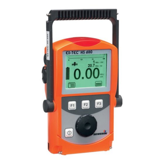
- Page 2 Supporting bracket Signal light Buzzer Gas input USB port Display Function keys Jog dial ON/OFF key Connection for Connector power supply EX-TEC HS 680 device overview Fig. 1: Bar display Selected Measurement value application Alarm Capacity 0.90 disposable battery/ Unit VOL%...
- Page 3 Display symbols General Menu Fault Carry out device inspection Tab (jump to next input Cancel field) Buzzer off Set zero point Take sample Purge Save Stop measurement Delete Information Capacity disposable bat- Open stored comment tery/rechargeable battery Open stored inspector Applications Inspection above ground Structure...
- Page 4 Information about this document The warnings and notes in this document mean the following: DANGER! Risk of personal injury. Will result in serious injury or death. WARNING! Risk of personal injury. Can result in serious injury or death. CAUTION! Risk of personal injury. Can result in injury or a risk to health.
-
Page 5: Table Of Contents
Contents Page General ..................1 Warranty ..................1 Purpose ..................2 Intended use ................3 General safety information ............4 Allocation of tasks to applications ..........5 Features ...................6 Visual and audible signals ............7 Sensors ..................8 Explosion protection ..............9 2.3.1 Passive explosion protection ..........9 2.3.2 Active explosion protection ..........10 Operation ................ - Page 6 Contents Page 3.2.14 Device inspection ..............36 3.2.15 Gas type CxHy ..............36 3.2.16 Device information ...............37 Settings ...................37 3.3.1 Opening settings ..............37 3.3.2 Settings menu structure ............39 3.3.3 Adjustment ................40 3.3.4 System .................42 3.3.5 Alarms ..................44 3.3.6 Date/time ................44 3.3.7 Memory ................44 Power supply .................46 Suitable disposable/rechargeable battery types .....46 Operation with rechargeable batteries ........47...
- Page 7 Contents Page Adjustment ................62 5.2.1 Scope ...................62 5.2.2 Test gases for the adjustment ..........63 5.2.3 Special features of adjustment with gas mixture ....64 5.2.4 Preparation ................65 5.2.5 Performing the adjustment ...........65 5.2.5.1 Adjusting the zero point.............66 5.2.5.2 Adjusting the sensitivity .............66 5.2.6 Carrying out an oxygen adjustment ........68 5.2.6.1...
- Page 8 Contents Page 7.6.3 Electrostatic charge ..............84 Accessories and consumables ..........85 Declaration of conformity ............86 Inspection protocols ..............87 7.9.1 Test with individual gases .............87 7.9.2 Test with gas mixture ............89 7.10 Advice on disposal ..............91 7.11 Terminology and abbreviations ..........92 7.12 Referenced documents ............93 Index ..................94...
-
Page 9: General
● Repairs and maintenance must only be carried out by special- ist technicians or other suitably trained personnel. Only spare parts approved by Hermann Sewerin GmbH may be used when performing repairs. ● Use only suitable battery types, otherwise the device will not be explosion-proof. -
Page 10: Purpose
1 General Purpose The EX-TEC HS 680 and the models 660, 650 and 610 are hand- held measuring devices which can be used for all gas pipeline testing applications. The devices are designed for professional industrial use and require the necessary specialist knowledge for working in gas pipelines. -
Page 11: Intended Use
1 General Intended use This device is intended for professional residential and commer- cial use including small firms and commercial operations. The appropriate specialist knowledge is required to operate the device. The device may only be used to measure the following gases (depending on the device model and additional equipment): ●... -
Page 12: General Safety Information
1 General General safety information ● The device has been tested to ensure that it is explosion-proof in accordance with European standards (CENELEC). ● The device must only be switched on with fresh air. ● Do not use this device in oxygen-enriched atmospheres, oth- erwise it will not be explosion-proof. -
Page 13: Allocation Of Tasks To Applications
1 General Allocation of tasks to applications The table is designed to help you decide which application to choose for which activity (in accordance with /3/). -
Page 14: Features
2 Features Features The device comes in four models: EX-TEC HS 680 EX-TEC HS 660 EX-TEC HS 650 EX-TEC HS 610 The models are suitable for the following applications: Application HS 680 HS 660 HS 650 HS 610 Inspection above ground ×... -
Page 15: Visual And Audible Signals
2 Features Visual and audible signals The device features two alarms: ● Signal light on top of device (visual signal) ● Buzzer on side of device (audible signal) The signals indicate alarms and faults. The device also emits signals when it is switched on and off. If this symbol appears on the display, the audible signal can be switched off. -
Page 16: Sensors
2 Features Sensors The device features three types of sensor: ● Gas-sensitive semiconductor (SC) ● Infrared sensor (IR) ● Electrochemical sensor (EC) Application Measuring range Sensors Inspection above 1 ppm – 10 % vol. SC, IR ground Plants 1 ppm – 100 % vol. SC, IR Measuring in bar 0.0 –... -
Page 17: Explosion Protection
2 Features Explosion protection 2.3.1 Passive explosion protection The device is assigned to the following explosion-proof groups: Explosion-proof For the following When group atmospheres using II2G Ex d e ib IIB T4 Gb – Methane CH Device without – Propane C –... -
Page 18: Active Explosion Protection
2 Features 2.3.2 Active explosion protection The functional safety test applies to: Applications: Warning %LEL Warning ExTox Gas types: Measuring range: – Methane CH 0 – 100% LEL – Propane C 0 – 100% LEL Gases: Measuring range: As per: –... -
Page 19: Operation
3 Operation Operation General information on operation 3.1.1 Keys and jog dial The ON/OFF key is the only control on the device that does not change its function. When switched on, the device is operated using the jog dial and function keys to navigate the display. -
Page 20: Selecting/Exiting Menus And Menu Items
3 Operation 3.1.2 Selecting/exiting menus and menu items Functions, applications and settings etc. are selected via the main menu (for short: Menu). This menu has submenus and menu items. Refer to section 3.2.1 for information on accessing the menu. Selecting submenus/menu items Submenus and menu items are selected and opened using the jog dial and/or the function keys. - Page 21 3 Operation The start screen appears on the display. Display: – Device type: EX-TEC HS 680 – User: ® EX-TEC HS 680 Frank Smith City Council Frank Smith City Council Leakage Delivery Leakage Delivery – Firmware version: V2.000 13:02 V2.000 17.09.2018...
-
Page 22: Selecting/Changing The Application
3 Operation Display: – Current reading: zero when device is switched on with fresh Fig. 5: Inspection above ground measuring mode WARNING! Risk to life from using miscalibrated or faulty devices Gas warning devices must be regularly checked before use. ●... -
Page 23: Differences Between Measuring Mode And Settings Mode
3 Operation which application is activated first when the device is switched on in the Settings under System (see section 3.3.4). ● Press Menu. Select the menu item for the application you want to use. a) Press function key F3. The device switches to the next ap- plication. -
Page 24: Accessing The Menu (Measuring Mode Menu Structure)
3 Operation Depending on the application, the measurement will have to be saved or started and then stopped (see section 3.2.12). WARNING! Risk to life from operating signal failure When the device is used as a gas warning device (Warn- ing %LEL and Warning ExTox applications), an operat- ing signal must always sound in measuring mode. -
Page 25: Zero Point
3 Operation Once you have started a measurement Start measurement in the menu becomes Stop measurement. In some applications this menu item is called Save measurement. You can find detailed information on starting, stopping and saving measurements in section 3.2.12. Protocol does not appear in the menu until you save a protocol for the first time. -
Page 26: Inspection Above Ground
3 Operation The Setting zero point function can also be accessed using the relevant symbol in the Inspection above ground, Plants and Structure applications. 3.2.3 Inspection above ground The measuring mode can be changed for the Inspection above ground application via this menu item. Area of use –... -
Page 27: Plants
3 Operation 3.2.4 Plants The measuring mode can be changed for the Plants application via this menu item. Area of use – Measuring minimal gas concentrations in freely accessible gas pipes and systems (e.g. gas pipes on bridges, above- ground inverted siphons, biogas plants) –... -
Page 28: Measuring In Bar Holes
3 Operation 3.2.5 Measuring in bar holes The measuring mode can be changed for the Measuring in bar holes application via this menu item. Area of use – Measuring gas dispersal in the ground – Locating the possible leakage point and classifying the leak Symbol Unit –... -
Page 29: Ethane Analysis
3 Operation 3.2.6 Ethane analysis Selecting Ethane analysis from the menu opens an overview of the gases that can be detected. The device automatically returns to measuring mode. Note: The ethane analysis cannot be started with the Ethane analysis menu item. Information about carrying out the ethane analysis can be found in section 3.2.6.3. -
Page 30: General Information On Ethane Analysis
3 Operation Measurement data display – Digit, for example, 0 % vol. CO 20.9 % vol. O VOL% CO2 20.9 VOL% O2 9.0 % vol. C – Bar display with quasi-logarith- VOL% mic scale (for C CxHy Fig. 10: Ethane analysis measuring mode 3.2.6.1 General information on ethane analysis Ethane analysis is used to demonstrate the presence of natural gas and to distinguish between natural gas and swamp gas. - Page 31 3 Operation The device checks the concentration at the start of the analysis and prevents the analysis being carried out if the concentration is too low. Gas sample Analysis Device response concentration is … > 1 % vol. Definitely Analysis can be carried out possible 1 % vol.
-
Page 32: Purging The Detector
3 Operation 3.2.6.2 Purging the detector The detector for ethane analysis must be kept clean at all times to prevent distortion of measurement results. When the device is in use, however, higher hydrocarbons (e.g. propane, butane) can accumulate in the detector and contaminate it. The detector is automatically purged after every ethane analysis. -
Page 33: Carrying Out An Ethane Analysis
3 Operation 3.2.6.3 Carrying out an ethane analysis The device is in measuring mode. 1. Make sure the device is drawing in fresh air. 2. Change to the Ethane analysis application. 3. The ethane analysis is generally performed on a bar hole. Use the localisation probe and a probe hose. -
Page 34: Evaluating An Ethane Analysis
3 Operation Analysis C2H6 C2H6 C3H8 C3H8 250 s 088 Seconds Fig. 11: Mode of curve of an analysis in progress When the analysis is complete, the Save symbol appears. 7. Press Save. 8. If necessary enter a Comment on the analysis. a) Select the characters required using the jog dial. - Page 35 3 Operation A protocol contains the following Analysis information about the gas sample: C2H6 ???? – Analysis of the gas components: C3H8 ---- ???? – – – – 250 s – Curve; peaks of the gas compo- 17.09.2018 11:21 12/47 nents definitely present in the...
- Page 36 3 Operation Criteria for determining good analysis quality ● Methane is definitely present. ● Methane concentration is 1 % vol. ● Peaks of the gas components present are clearly recognisable. Criteria for determining the presence of natural gas ● Good analysis quality (see above) ●...
-
Page 37: Structure
3 Operation 3.2.7 Structure The measuring mode can be changed for the Structure applica- tion via this menu item. Area of use – Measuring minimal gas concentrations in structures. – Locating the source of gas Symbol Unit – ppm (parts per million) –... -
Page 38: Gas Measuring
3 Operation 3.2.8 Gas measuring The measuring mode can be changed for the Gas measuring application via this menu item. WARNING! Risk to life due to absence of alarm The device does not sound an alarm in the gas measur- ing application. -
Page 39: Warning %Lel
3 Operation 3.2.9 Warning %LEL The measuring mode can be changed for the Warning %LEL application via this menu item. WARNING! Risk to life from operating signal failure If the operating signal does not sound, the device is not safe to operate. ●... -
Page 40: Warning Extox
3 Operation 3.2.10 Warning ExTox The measuring mode can be changed for the Warning ExTox application via this menu item. WARNING! Risk to life from operating signal failure If the operating signal does not sound, the device is not safe to operate. ●... -
Page 41: Settings
3 Operation CAUTION! Health risk due to late alarm If you change the device from the Warning ExTox appli- cation to another application, data that could initiate an STEL or LTEL alarm is reset to zero. ● Only switch from Warning ExTox to another application once you have left the work area being monitored. - Page 42 Once the first comment has been entered, the Open stored comments function will become available. The stored measurements can be displayed on a computer using a readout program. The program is available at www.sewerin. com. Starting a measurement 1. Press Menu.
-
Page 43: Protocols
3 Operation b) Then confirm your entry/selection with OK. Press Esc if you do not wish to enter a comment for the measurement. The measurement is saved as a protocol. The protocol name is formed from the date, time and comment. Saving a measurement 1. -
Page 44: Device Inspection
3 Operation You can find information on how to clear all protocols of one pro- tocol type in section 3.3.7. 3.2.14 Device inspection The device inspection can be used to check the general status and the indication accuracies. Device inspection only appears in the menu when the integrated device inspection is switched on. -
Page 45: Device Information
3 Operation 3.2.16 Device information The following device information is shown under Device infor- mation in the menu: ● Installed electrochemical sensors: gas, installation date, war- ranted/expected lifetime ● Firmware: version, date ● Service: date of the last service, date of the next service Settings The following menus and menu items are included under Settings: ●... - Page 46 3 Operation Note: You can change the PIN code at any time. SEWERIN recommends setting a different PIN code after initial start-up so that only authorised personnel have access to the settings. 3. Enter the PIN code from left to right. The active digit is always displayed with a black background.
-
Page 47: Settings Menu Structure
Memory Clear Interval Memory mode Exit Exit Measuring mode Fig. 19: Settings menu structure for EX-TEC HS 680 (gas type: meth- ane) Note: The number and names of available menu items depend on the device model and optional additional equipment. -
Page 48: Adjustment
3 Operation 3.3.3 Adjustment The Adjustment menu is used to set the sensors. WARNING! Danger of death due to incorrect adjust- ment Incorrect adjustment can lead to incorrect measurement results. This means that the user may not be warned about dangerous gas concentrations in time. - Page 49 3 Operation Adjustment CO2 Used to adjust the infrared sensor for carbon dioxide CO in the % vol. range. Applications: – Measuring in bar holes – Ethane analysis – Warning ExTox Adjustment O2 Used to adjust the electrochemical sensor for oxygen O in the % vol.
-
Page 50: System
Used to change or reset the PIN code. Note: If you lose the PIN code, you must contact SEWERIN Service. If the PIN code is set to 0000, you will not be asked to enter it. The settings can then be accessed by anyone. - Page 51 3 Operation Battery Used to set the type of disposable/rechargeable battery used. NOTICE! Damage possible due to device overheating If the battery type is not correctly set, the device can overheat. ● Always enter the correct battery type. Autostart Sets the application that is automatically activated when the de- vice is switched on.
-
Page 52: Alarms
3 Operation 3.3.5 Alarms Sets the alarm thresholds for the gas types and gases. Alarm AL3 cannot be set. It always occurs at the end of the measuring range. There is detailed information on alarms in section 7.2. AL1 alarm Used to set the pre-alarm. - Page 53 3 Operation Clear Used to clear protocols. The different protocol types must each be cleared separately. All protocols in one protocol type are cleared at once. You can find information on clearing individual protocols in sec- tion 3.2.13. Interval Sets the interval at which measurement data is automatically saved.
-
Page 54: Power Supply
● Only use batteries supplied by SEWERIN. Other dis- posable/rechargeable batteries, which have not been supplied by SEWERIN, may only be used if they meet the requirements of /8/. ● In each battery compartment use only batteries that are identical with respect to type (disposable or recharge- able), capacity and manufacturer. -
Page 55: Operation With Rechargeable Batteries
4 Power supply Disposable battery requirements ● Disposable alkaline batteries ● Size: AA, type: LR6 as per /11/ ● The creepage distance and air gap between the poles must not be less than 0.5 mm in accordance with /8/. Rechargeable battery requirements ●... -
Page 56: Charging
4 Power supply 4.2.1 Charging The device can be charged via: ● Connection for power supply ● Docking station TG8 DANGER! Risk of explosion from sparks High charging amperage occurs when charging batteries in explosive areas. The mains adapter is not explosion proof. ●... -
Page 57: Rechargeable Battery Maintenance
4 Power supply 4.2.2 Rechargeable battery maintenance If the device is not used for a long period of time, it is advisable to fully discharge the battery before recharging it again. A full discharging and recharging process takes approx. 11 hours (8 hours to discharge + 3 hours to recharge). -
Page 58: Replacing Disposable/Rechargeable Batteries
4 Power supply Replacing disposable/rechargeable batteries DANGER! Risk of explosion from sparks The device is not explosion proof when the housing is open. ● Only ever open the battery compartment outside of explosive areas. A 2.5 mm Allen key (supplied) is required to open the battery compartment on the back of the device. -
Page 59: Maintenance
5 Maintenance Maintenance In accordance with the legal regulations, device maintenance comprises the following elements: ● Device inspection including test of indication accuracy ● Adjustment ● Servicing All inspections must be documented. The documentation must be retained for at least one year. WARNING! Risk to life from using miscalibrated or faulty devices If the device is used as a gas warning instrument (Warn-... -
Page 60: Frequency
5 Maintenance 5.1.1.2 Frequency The frequency of the device inspection depends on the appli- cation. Application When to test Legal basis Inspection above Before starting work and ground if out of use for long pe- riods Plants Weekly to every six months Measuring in bar holes... -
Page 61: Documentation
The device inspection protocols can be opened at any time (see section 3.2.13). They can also be displayed on a computer using a readout program. The program is available at www.sewerin.com. The Perform device inspection symbol appears when a device inspection is due. It is visible in the display until the complete integrated device inspection has been car- ried out successfully for the selected application. -
Page 62: Order
5 Maintenance 3. Enter your PIN code. 4. Select System. 5. Select Device inspection. 6. Select Yes. 7. Apply the setting with OK. 8. Exit the settings with Back. 5.1.1.5 Order You can carry out the device inspections and the associated tests for the applications (groups) that are due to be inspected in any order you wish. -
Page 63: Application Test
Note: Use of test gases not provided by SEWERIN can cause inter- ference. The concentration of the test gas used must match the specified... -
Page 64: Performing The Device Inspection
5 Maintenance Changing the test gas concentration If no test gas with the specified concentrations is available for the test, the values can be changed according to the test gas used under Test gas in the adjustment menu (see section 3.3.3). 5.1.2 Performing the device inspection 5.1.2.1 Accessing the device inspection... -
Page 65: Concluding The Device Inspection
5 Maintenance 5.1.2.2 Concluding the device inspection After all the tests have been carried out as described in sec- tion 5.1.3 to 5.1.5, the Save symbol will appear in the display. An integrated device inspection is concluded by saving it. Up to 40 device inspections can be saved. -
Page 66: Testing The General Status
5 Maintenance The device inspection is saved as a protocol. An overview with the device inspection results is displayed. This overview includes a list of all gas types for which the de- vice is configured. Gas types for which the indication accuracy was successfully tested in the device inspection are flagged with OK. -
Page 67: Signals
After a maximum of 10 seconds an error message should ap- pear. This indicates that the pump is working correctly. If the error message does not appear, the pump may be faulty. The device must be tested by SEWERIN Service. -
Page 68: Testing Indication Accuracy With Supply Of Fresh Air
5 Maintenance 2. Release the gas input again. After approximately 5 seconds, the error message should disappear again. Otherwise there is a fault (see section 6). 5.1.4 Testing indication accuracy with supply of fresh air The indication accuracy with supply of fresh air test is part of the device inspection (see section 5.1.1.1). - Page 69 5 Maintenance Note: Details of how to use the test set can be found in the accompa- nying operating instructions. The procedure for testing with a gas mixture and individual gas is the same. The device inspection has been opened. 1.
-
Page 70: Adjustment
5 Maintenance Test gas test unsuccessful If a Test gas … test was not carried out successfully, the mes- sage Test gas not OK appears. A test may be unsuccessful for the following reasons: Cause Corrective action Connections leaking Repeat check, checking the seal on the connections Measurement values outside Adjustment required... -
Page 71: Test Gases For The Adjustment
5 Maintenance 5.2.2 Test gases for the adjustment The following test gases can be used for adjustment: Suitable test gases for Zero point Sensitivity ● Fresh air ● Gas mixture ● 10 ppm CH ● 100 ppm CH ● 1000 ppm CH ●... -
Page 72: Special Features Of Adjustment With Gas Mixture
5.2.3 Special features of adjustment with gas mixture If a SEWERIN gas mixture is used as a test gas, several gases can be adjusted in a single step. SEWERIN recommends a gas mixture comprising the test gas ExTox IR (2.2 % vol. -
Page 73: Preparation
Note: When adjusting the gas-sensitive semiconductor (Inspection above ground and Structure/Plants groups), you must apply a conditioner. ● SEWERIN recommends applying separate conditioners for methane CH on the one hand and propane C / butane C on the other. -
Page 74: Adjusting The Zero Point
5 Maintenance 5.2.5.1 Adjusting the zero point For all gases except oxygen O , the zero point is adjusted follow- ing the same procedure. Note: When adjusting the zero point of carbon dioxide CO , a carbon dioxide filter must be used. This applies to both the zero point adjustment for Adjustment CO2 in the menu and Adjustment gas mixture warning. - Page 75 5 Maintenance The following resources are needed for adjusting the sensitivity: ● Test gas Information on test gases for adjustment can be found in Sec- tion 5.2.2. ● Test set for the supply of test gas (e.g. SPE VOL) Note: Details of how to use the test set can be found in the accompa- nying operating instructions.
-
Page 76: Carrying Out An Oxygen Adjustment
5 Maintenance 8. Press OK to confirm. The device is adjusted. The reading shows the specified value (for example, 2.20 % vol. CH 9. Let go of the release button on the test set. 5.2.6 Carrying out an oxygen adjustment As oxygen is a component of fresh air, the procedure for adjusting oxygen is different from the procedure for all other gases. -
Page 77: Adjusting The Sensitivity For Oxygen
20.9 % vol. Servicing The device must only be serviced and repaired by SEWERIN Service. ● Send the device to SEWERIN for repairs and for annual main- tenance. Note: If there is a service agreement in place, the device can be ser- viced by the mobile maintenance service. -
Page 78: Faults
Check test gas concentration Test gas Zero point Adjustment required Adjustment required XFLASH Error can only be corrected by SEWERIN Service SEWERIN Service Error unknown Error can only be corrected by SEWERIN Service SEWERIN Service IR sensor Error can only be corrected by... -
Page 79: Appendix
7 Appendix Appendix Specifications and permitted operating conditions Dimensions (W×D×H): Approx. 148 × 57 × 205 mm Approx. 148 × 57 × 253 mm with supporting bracket Weight: Approx. 1000 g, depending on equipment Operating position: Protection rating: IP54 Power supply: 4 cells, either: –... -
Page 80: Alarms
7 Appendix Pressure at gas input: 100 mbar, maximum Operation: – ON/OFF key – Jog dial – 3 function keys Alarms WARNING! Risk to life from dangerous gas concen- trations An alarm always indicates danger. ● Take all necessary measures for your own safety and the safety of others immediately. - Page 81 7 Appendix Type: Main alarm Adjustable: Latching: Trigger: AL2 alarm threshold exceeded Indicator: – Audible signal – Visual signal – AL2 notification on display Acknowledge- – Possible for audible signal when alarm threshold ment: AL2 is exceeded – Possible overall after level falls below alarm thresh- old AL2 Reset: –...
- Page 82 7 Appendix Type: Warning of gas concentration in ppm range Adjustable: Latching: Trigger: Alarm threshold AL4 exceeded Indicator: – Audible signal – Visual signal – AL4 notification on display Acknowledge- – Possible for audible signal when alarm threshold ment: AL4 is exceeded Reset: –...
-
Page 83: Occupational Exposure Limits (Oel) And Excess Factors (Stel And Ltel)
7 Appendix 7.2.2 Occupational exposure limits (OEL) and excess factors (STEL and LTEL) The short-time exposure limit (STEL) is calculated by multiplying the OEL by the excess factor over an averaging time of 15 min- utes, as per /15/. The long-time exposure limit (LTEL) is obtained from the OEL over an averaging period of 8 hours, as per /15/. -
Page 84: Setting Ranges For Gas Types
7 Appendix 7.2.4 Setting ranges for gas types LEL values are specified as per /12/ and /14/. The setting for AL1 must not exceed the setting for AL2. Gas type All C Threshold 10 % LEL 50 % LEL % LEL 0.45 % vol. -
Page 85: Limit Values For The Device Inspection
7 Appendix Limit values for the device inspection Zero point Sensitivity Specification Deviation Specification Deviation 0.00 % vol. ±0.15 % vol. 2.20 % vol. ±0.20 % vol. 0.00 % vol. ±0.12 % vol. 1.00 % vol. ±0.16 % vol. 0.00 % vol. ±0.12 % vol. -
Page 86: Memory Capacity
7 Appendix Memory capacity The total memory capacity of the device is divided up as follows: Protocol type Maximum number of storable protocols Ethane analysis Device inspection Measurement There is a choice of two memory modes (see section 3.3.7). The selected memory mode applies for all protocol types. -
Page 87: Sensors
7 Appendix Sensors Note: Probes increase the stated response times. 7.5.1 Infrared sensors (IR) 7.5.1.1 Methane CH , propane C , butane C Warning %LEL and Warning ExTox Type: Infrared sensor Measuring range: 0 – 100 % LEL Measuring error: As per /9/ –... -
Page 88: Propane C 3 H
7 Appendix 7.5.1.2 Methane CH , propane C for gas measuring Type: Infrared sensor Measuring range: 0 – 100 % vol. Measuring error CH ±3 % vol. Response times: – CH < 9 s < 17 s – C < 11 s <... -
Page 89: Carbon Dioxide Co For Measuring In Bar Holes
7 Appendix 7.5.1.4 Carbon dioxide CO for measuring in bar holes Type: Infrared sensor Measuring range: 0 – 30 % vol. Measuring error: ±1.04 % vol. Response time: < 20 s Temperature range: -20 ºC – +40 ºC Interference: None Lifetime: –... -
Page 90: Carbon Monoxide Co
7 Appendix 7.5.2.2 Carbon monoxide CO Type: Electrochemical sensor Measuring range: 0 – 500 ppm – Lower limit 4 ppm Resolution: 1 ppm Measuring error: ±3 % / ±3 ppm (±3 digits) ±5 ppm (long-term stability) as per /4/ Zero point deviation: 7 ppm Response time: <... -
Page 91: Hydrogen Sulphide H S
7 Appendix 7.5.2.3 Hydrogen sulphide H Type: Electrochemical sensor Measuring range: 0 – 100 ppm – Lower limit 1 ppm Resolution: 1 ppm Measuring error: ±3 % / ±3 ppm (±3 digits) ±2 ppm (long-term stability) as per /4/ Zero point deviation: 1 ppm Response time: <... -
Page 92: Technical Information
7 Appendix Technical information 7.6.1 Identification sticker (back of device) The symbols on the sticker mean the following: Only ever open the battery compartment outside of explosive areas. Read the operating instructions. 7.6.2 Cleaning The device must only be cleaned with a damp cloth. NOTICE! Possible damage to property from unsuita- ble cleaning agents Unsuitable cleaning agents can chemically corrode the... -
Page 93: Accessories And Consumables
12 bar Test gas 10 ppm CH in synthetic air, test gas ZT24-10000 can 1 l, pressure approx. 12 bar Other accessories and consumables are available for the prod- uct. Please contact our SEWERIN sales department for further information. -
Page 94: Declaration Of Conformity
7 Appendix Declaration of conformity Hermann Sewerin GmbH hereby declares that the EX-TEC ® HS 680/660/650/610 system fulfils the requirements of the fol- lowing guidelines: ● 2014/34/EU ● 2014/30/EU Gütersloh, 2016-04-20 Dr S. Sewerin (CEO) The complete declaration of conformity can be found online. -
Page 95: Inspection Protocols
7 Appendix Inspection protocols 7.9.1 Test with individual gases INSPECTION PROTOCOL EX-TEC® HS 680 Manuf. no. (e.g.: 064 01 0501) 09.04.2019 1.0 General status 1.1 – Perfect condition (e.g.: Y / N) 1.2 – Fine dust filter correct (e.g.: Y / N) 1.3 –... - Page 96 7 Appendix 8.0 Gas measuring (absence of gas) 8.1 Zero point – Display -0.3 – +0.3 % vol. 8.2 Test gas 100 % vol. CH – Display 98 – 102 % vol. 9.0 Measuring in bar holes 9.1 Zero point –...
-
Page 97: Test With Gas Mixture
7 Appendix 7.9.2 Test with gas mixture INSPECTION PROTOCOL ExTox IR EX-TEC® HS 680 Manuf. no. (e.g.: 064 01 0501) 09.04.2019 1.0 General Status 1.1 - Perfect condition (e.g.: Y / N) 1.2 - Fine dust filter correct (e.g.: Y / N) 1.3 - Disposable/rechargeable battery capacity (e.g.: ¼) 2.0 Pump check 2.1 - Pump error F100 in seal... - Page 98 7 Appendix 6.0 Warning %LEL / Warning ExTox (test gas ExTox IR) 6.1 CH (2.20 % vol.) – Display 45 – 55 % LEL – Display 2.00 – 2.40 % vol. 6.2 CO (2.00 % vol.) – Display 1.80 – 2.20 % vol. 6.3 O (0 % vol.) –...
-
Page 99: Advice On Disposal
16 05 05 Disposable battery, re- 16 06 05 chargeable battery End-of-life equipment Used equipment can be returned to Hermann Sewerin GmbH. We will arrange for the equipment to be disposed of appropriately by certified specialist contractors free of charge. -
Page 100: Terminology And Abbreviations
7 Appendix 7.11 Terminology and abbreviations ● Alarm CENELEC ● European Committee for Electrotechnical Standardization ● Electrochemical sensor Gas type ● Hydrocarbon C , which can be meas- ured with the IR ● One of the available gas types must al- ways be set at a given time, as it is not possible to measure more than one gas type at the same time. -
Page 101: Referenced Documents
7 Appendix 7.12 Referenced documents The following standards, guidelines and regulations are referred to in these operating instructions: BG RCI (German Social Accident Insurance Institution for the raw materials and chemical industry) Leaflet T 021 (DGUV Information 213-056) Gas Warning Devices for Toxic Gases/Vapours and Oxygen – Use and Operation. -
Page 102: Index
8 Index Index Device information 37 Device inspection 36, 43, 51 Accessories 85 accessing 56 Adjustment 40, 62 concluding 57 CO 41 documentation 53 CO2 41 frequency 52 CxHy 40 integrated 53 CxHy ppm 40 limits 77 gas mixture measuring 41 order 54 gas mixture warning 41 performing 56... - Page 103 8 Index Menu 12, 16 accessing 16 Gas measuring 30 exiting 12 Gas mixture 64 selecting 12 Gas-sensitive semiconductor see Sen- Menu item exiting 12 Gas type CXHY 43 selecting 12 General status 58 Menu structure 16, 39 Housing 58 Occupational exposure limit 75 OEL 75 Operating signal 7...
- Page 104 8 Index Settings 15, 33, 37 menu structure 39 opening 37 Signal 59 audible 7 visual 7 Stack memory 45 STEL 75 Structure 29 System 42 Test gas adjustment 63 for the device inspection 54 Test gas concentration 42 changing 56 Time 44 Unit setting 43...
- Page 105 Hermann Sewerin GmbH SEWERIN SARL Robert-Bosch-Straße 3 17, rue Ampère – BP 211 33334 Gütersloh, Germany 67727 Hoerdt Cedex, France Tel.: +49 5241 934-0 Tél. : +33 3 88 68 15 15 Fax: +49 5241 934-444 Fax : +33 3 88 68 11 77 www.sewerin.com...
Need help?
Do you have a question about the EX-Tec HS 680 and is the answer not in the manual?
Questions and answers