Advertisement
Quick Links
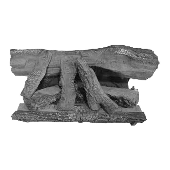
Log Set Assembly:
Models: CFL-24NG/LP
CFL-24NG/LP-B
CFL-24NG/LP-C
CAUTION: Carefully remove the logs from the
packaging. Logs are fragile!
NOTICE: To simplify the installation process,
positively identify each individual log before
beginning installation.
NOTICE: Burner styles may vary.
Follow the instructions for log placement using figures
and instructions below. Use the "flat areas" indicated in
the photos to guide you through the process. Use the
log numbers to identify the logs. Check to make sure
the tabs on the side of burner legs are bent outward. Set
log grate by resting it down and sliding it toward burner.
Make sure right and left grate bars slide on outside of
burner legs between tabs.
BURNER STYLE MAY VARY
1 1
LOG #1 & #2: (SRV481-766)
Set logs #1 and 2 in front of the burner. Rest the bottom
two notches over the extended material of the burner legs.
Slide it towards the burner until it comes in contact with
the burner.
FLAT AREA (Use to place log #6)
LOG #5: (SRV481-701)
This log sits toward the back on top of the brackets located
on the right and the left. The two notches on the bottom of
the log should rest over these brackets. The back of this
log should line up with the back end of the brackets.
2 2
5 5
Heat & Glo • CFL-24NG/LP, CFL-24NG/LP-B, CFL-24NG/LP-C • 481-926 Rev. E • 9/21
1 1
3 3
5 5
2 2
4 4
3 3
LOG #3 & #4: (SRV481-755)
Set logs #3 and #4 between the grate and logs #1 and 2
with the bark detail toward the outside. Logs #3 and #4
should be even with logs #1 and #2 from one side to the
other. Slide grate to hold log in place.
6 6
LOG #6: (SRV481-705)
Set log #6 on the top of log #1 and the burner toward the
left by following the flat area mark (on log #1). Make sure
that the log will clear the ports on the top of the burner.
LOG PLACEMENT
INSTRUCTIONS
6 6
7 7
8 8
9 9
BRACKETS
(Use to place log #5)
4 4
FLAT AREA (For log #7)
10
10
1
Advertisement

Related Manuals for Heatilator CFL-24NG


Summary of Contents for Heatilator CFL-24NG
- Page 1 The back of this that the log will clear the ports on the top of the burner. log should line up with the back end of the brackets. Heat & Glo • CFL-24NG/LP, CFL-24NG/LP-B, CFL-24NG/LP-C • 481-926 Rev. E • 9/21...
- Page 2 #5. Rest the (pointed end) onto the flat area of the corner of log #8. front end of the log on the top flat area of log #6. Heat & Glo • CFL-24NG/LP, CFL-24NG/LP-B, CFL-24NG/LP-C • 481-926 Rev. E • 9/21...
- Page 3 Place the dime-size ember pieces near the port holes in the burner top. Failure to follow this procedure will likely cause lighting and sooting problems. Place Vermiculite Heat & Glo • CFL-24NG/LP, CFL-24NG/LP-B, CFL-24NG/LP-C • 481-926 Rev. E • 9/21...
Need help?
Do you have a question about the CFL-24NG and is the answer not in the manual?
Questions and answers