Table of Contents
Advertisement
Quick Links
Advertisement
Table of Contents

Subscribe to Our Youtube Channel
Related Manuals for Evco EVF815


Summary of Contents for Evco EVF815
- Page 1 Evco S.p.A. EVF815 | Installer manual ver. 1.1 | Code 144F815E114 EVF815 Split execution controller for temperature-controlled blast chillers (with capacitive touch-key user interface, which can be integrated into the unit) ENGLISH INSTALLER MANUAL ver. 1.1 CODE 144F815E114 page 1 of 58...
- Page 2 Evco S.p.A. EVF815 | Installer manual ver. 1.1 | Code 144F815E114 Important Important Read this document thoroughly before installation and before use of the device and follow all recommendations; keep this document with the device for future consultation. The following symbols support reading of the document:...
-
Page 3: Table Of Contents
Evco S.p.A. EVF815 | Installer manual ver. 1.1 | Code 144F815E114 Index INTRODUCTION ..........................2 Introduction............................2 Summary table of the main features and the models available ..............2 DESCRIPTION ............................ 2 Description of the user interface......................2 Description of the control module ......................2 DIMENSIONS AND INSTALLATION ...................... - Page 4 Evco S.p.A. EVF815 | Installer manual ver. 1.1 | Code 144F815E114 Restoring the factory settings ......................2 List of configuration parameters ......................2 SIGNALS AND INDICATIONS........................ 2 10.1 Signals ............................2 10.2 Indications ............................ 2 ALARMS ............................2 11.1 Alarms ............................2 ERRORS ............................
-
Page 5: Introduction
Evco S.p.A. EVF815 | Installer manual ver. 1.1 | Code 144F815E114 INTRODUCTION Introduction EVF815 is a digital controller studied to manage temperature-controlled blast chillers, which can be mechanically and aesthetically integrated into the unit. The controller is fitted with: clock... -
Page 6: Summary Table Of The Main Features And The Models Available
Evco S.p.A. EVF815 | Installer manual ver. 1.1 | Code 144F815E114 Summary table of the main features and the models available The following table illustrates the main features of the device and the models available. “ / “ indicates the feature can be set via a configuration parameter. - Page 7 Evco S.p.A. EVF815 | Installer manual ver. 1.1 | Code 144F815E114 evaporator fan door heating elements/condenser fan 16 A cabinet light/needle probe heating/UV light Communication port EVF815 serial port with MODBUS communication protocol • Other features EVF815 protection rating of the user interface...
- Page 8 Evco S.p.A. EVF815 | Installer manual ver. 1.1 | Code 144F815E114 Codes EVF815 codes EVF815P9 For further information, see chapter 14 "TECHNICAL DATA"; for other models contact the Evco sales network. page 8 of 58...
-
Page 9: Description
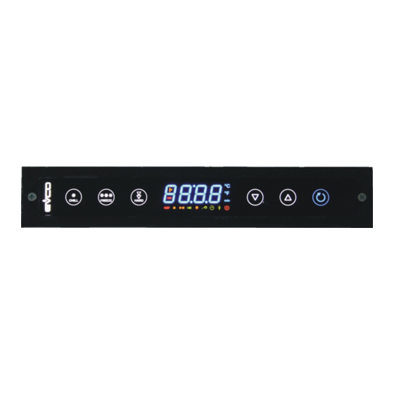
Evco S.p.A. EVF815 | Installer manual ver. 1.1 | Code 144F815E114 DESCRIPTION Description of the user interface The following drawing illustrates the aspect of the EVF815 user interface. The following table illustrates the meaning of EVF815 user interface parts. Part Meaning... -
Page 10: Description Of The Control Module
Evco S.p.A. EVF815 | Installer manual ver. 1.1 | Code 144F815E114 Description of the control module The following drawing illustrates the aspect of the EVF815 control module. The following table illustrates the meaning of EVF815 control module parts. Part Meaning... -
Page 11: Dimensions And Installation
EVF815 | Installer manual ver. 1.1 | Code 144F815E114 DIMENSIONS AND INSTALLATION User interface dimensions The following drawing illustrates the EVF815 user interface dimensions; these are expressed in mm (in). Control module dimensions The following drawing illustrates the EVF815 control module dimensions; these are expressed in mm (in). -
Page 12: User Interface Installation
Evco S.p.A. EVF815 | Installer manual ver. 1.1 | Code 144F815E114 User interface installation Rear of panel, with biadhesive tape. Control module installation On flat surface, with spacers. Installation warnings make sure that the device work conditions (temperature of use, humidity, etc.) lie within the limits indicated;... -
Page 13: Electric Connection
Evco S.p.A. EVF815 | Installer manual ver. 1.1 | Code 144F815E114 ELECTRIC CONNECTION Electric connection The following drawing illustrates the EVF815 electric connection. The utility managed by the K4 output, depends on parameter u1, as follows: door heating elements (u1 = 0, pre-defined setting) condenser fan (u1 = 1). -
Page 14: Connection Of The Terminating Resistors
14 "TECHNICAL DATA" disconnect the device power supply before proceeding with any type of maintenance do not use this device as a safety device for repairs and information regarding the device, contact the EVCO sales network. page 14 of 58... -
Page 15: User Interface
Evco S.p.A. EVF815 | Installer manual ver. 1.1 | Code 144F815E114 USER INTERFACE Foreword The following operating status exist: the “off” status (the device is not powered) the “stand-by” status (the device is powered and is off) the “on” status (the device is powered, is on and is in stand-by for the start-up of an operating cycle) the “run”... -
Page 16: Display Of The Temperature Detected By The Needle Probe
Evco S.p.A. EVF815 | Installer manual ver. 1.1 | Code 144F815E114 Display of the temperature detected by the needle probe Operate as follows: Make sure that the keyboard is not locked and that no procedure is in progress. Hold the DOWN key down for 1 s: the display will show the first label available. -
Page 17: Locking/Unlocking The Keyboard
Evco S.p.A. EVF815 | Installer manual ver. 1.1 | Code 144F815E114 Locking/unlocking the keyboard Operate as follows to lock the keyboard: Make sure no procedures are in progress Hold the DOWN key and the START/STOP key down for 1 s: the display will show “Loc” for 1 s. -
Page 18: Operation
Evco S.p.A. EVF815 | Installer manual ver. 1.1 | Code 144F815E114 OPERATION Foreword The devices can manage the following operating cycles: blast chilling and storage hard blast chilling and storage deep freezing and storage soft deep freezing and storage. For further information, see the next paragraphs Every operating cycle can be preceded by pre-cooling;... -
Page 19: Hard Blast Chilling And Storage
Evco S.p.A. EVF815 | Installer manual ver. 1.1 | Code 144F815E114 parameter r7 establishes the work set-point during blast chilling. Operate as indicated to stop the cycle: Hold the START/STOP key down. During blast chilling, the display shows the temperature detected by the needle probe and the LED is on. - Page 20 Evco S.p.A. EVF815 | Installer manual ver. 1.1 | Code 144F815E114 During the hard blast chilling phase, the display shows the residual time of the blast chilling duration and LED is on. To modify the residual time, operate as indicated: 6.2.1...
-
Page 21: Deep Freezing And Storage
Evco S.p.A. EVF815 | Installer manual ver. 1.1 | Code 144F815E114 Deep freezing and storage The temperature-controlled deep freezing and storage cycle is divided into the following two phases: deep freezing storage On conclusion of a phase, the device passes automatically to the next. -
Page 22: Soft Deep Freezing And Storage
Evco S.p.A. EVF815 | Installer manual ver. 1.1 | Code 144F815E114 To display the cabinet temperature, press and release the DEEP FREEZING key; to restore the normal display, press and release the DEEP FREEZING key again or do not operate for 15 s. -
Page 23: Pre-Cooling Start-Up
Evco S.p.A. EVF815 | Installer manual ver. 1.1 | Code 144F815E114 To display the cabinet temperature, press and release the BLAST CHILLING, DEEP FREEZING or the HARD/SOFT key; to restore the normal display, press and release the same key again or do not operate for 15 s. -
Page 24: Switching On Uv Light For Sterilisation Cycle
Evco S.p.A. EVF815 | Installer manual ver. 1.1 | Code 144F815E114 The second phase is completed successfully if the "temperature detected by the needle probe - cabinet temperature" difference is 1°C/1°F higher with respect to the previous control in at least 6 controls out of 8 (the controls are performed at time intervals corresponding to 1/8 of the time established with parameter r18;... -
Page 25: Haccp" Function
Evco S.p.A. EVF815 | Installer manual ver. 1.1 | Code 144F815E114 “HACCP” FUNCTION Foreword Using the “HACCP” function, it is possible to memorise up to 9 events for each of the 3 HACCP alarms, after which the most recent event overwrites the oldest. -
Page 26: Deleting The Information Relative To The Haccp Alarms
Evco S.p.A. EVF815 | Installer manual ver. 1.1 | Code 144F815E114 Inf. Meaning the critical value is 8.0 °C/8 °F the display is about to show the date and time the alarm occurred the alarm occurred in 2011 (continue...) the alarm occurred in the month of March (continue...) the alarm occurred on 26 March 2011 the alarm occurred at 16:00 (continue...) -
Page 27: Compressor Operating Hours Count
Evco S.p.A. EVF815 | Installer manual ver. 1.1 | Code 144F815E114 COMPRESSOR OPERATING HOURS COUNT Display of compressor operating hours Operate as follows: Make sure that the keyboard is not locked and that no procedure is in progress. Hold the DOWN key down for 1 s: the display will show the first label available. -
Page 28: Configuration
Evco S.p.A. EVF815 | Installer manual ver. 1.1 | Code 144F815E114 CONFIGURATION Setting the real date and time Operate as follows: Make sure that the keyboard is not locked and that no procedure is in progress. Hold the DOWN key down for 1 s: the display will show the first label available. - Page 29 Evco S.p.A. EVF815 | Installer manual ver. 1.1 | Code 144F815E114 Press and release the BLAST CHILLING key or do not operate for 15 s: the display will show the parameter label again. Operate as follows to exit the procedure: Hold the UP and DOWN key for 4 s or do not operate for 60 s The display will show the magnitude indicated in paragraph 5.3 "The display".
- Page 30 Evco S.p.A. EVF815 | Installer manual ver. 1.1 | Code 144F815E114 probe type - - - - = PTC = NTC °C decimal point - - - - = yes temperature unit of measurement (2) - - - - = °C = °F...
- Page 31 Evco S.p.A. EVF815 | Installer manual ver. 1.1 | Code 144F815E114 maximum duration of temperature-controlled blast chilling; see parameter r3 also maximum duration temperature-controlled deep freezing; see parameter r4 also work set-point during blast chilling; also work set-point -99.0 99.0 °C/°F (1)
- Page 32 Evco S.p.A. EVF815 | Installer manual ver. 1.1 | Code 144F815E114 "temperature detected by the needle probe - cabinet temperature" minimum difference such to consider the first phase of the test to verify correct insertion of the needle 99.0 °C/°F (1)
- Page 33 Evco S.p.A. EVF815 | Installer manual ver. 1.1 | Code 144F815E114 duration of compressor switch-on during the cabinet probe error (“Pr1” code) that occurs during post blast chilling storage; see also parameter C4 duration of compressor switch-on during the cabinet probe error (“Pr1”...
- Page 34 Evco S.p.A. EVF815 | Installer manual ver. 1.1 | Code 144F815E114 defrosting delay on start-up of storing = defrosting will be started on expiry of the time established with parameter d0 dripping duration (the compressor and the evaporator fan remain off during dripping and the defrosting output will be...
- Page 35 Evco S.p.A. EVF815 | Installer manual ver. 1.1 | Code 144F815E114 duration of a power cut such to cause the power cut alarm to be memorised ( “PF” code)when the power is supplied = the alarm will not be signalled...
- Page 36 Evco S.p.A. EVF815 | Installer manual ver. 1.1 | Code 144F815E114 condenser fan switch-off delay from compressor switch-off (11) evaporator fan delay from door closure, i.e. from the deactivation of the door micro switch input evaporator temperature above which the evaporator fan is -99.0...
- Page 37 Evco S.p.A. EVF815 | Installer manual ver. 1.1 | Code 144F815E114 effect caused by the activation of the high pressure input = no effect = the compressor and the evaporator fan will be off - - - - and the condenser fan will be on. On expiry of the time established with parameter i7, the display will show the flashing “HP”...
- Page 38 Evco S.p.A. EVF815 | Installer manual ver. 1.1 | Code 144F815E114 utility managed by the output K5 (14) = cabinet light (in this case, the DEEP FREEZING key and parameters i0 and u2 will assume significance) = needle probe heating (in this case, the DEEP...
- Page 39 Evco S.p.A. EVF815 | Installer manual ver. 1.1 | Code 144F815E114 (13) if the door is opened during defrosting or evaporator fan standstill, opening has no effect on the compressor (14) modify the parameter during the "stand-by" status to prevent damage to the utility...
- Page 40 Evco S.p.A. EVF815 | Installer manual ver. 1.1 | Code 144F815E114 SIGNALS AND INDICATIONS 10.1 Signals The following table illustrates the meaning of the signalling LEDS. Meaning Blast chilling LED. If it is on: blast chilling in progress. If flashing: a blast chilling and storage cycle will have been selected.
- Page 41 Evco S.p.A. EVF815 | Installer manual ver. 1.1 | Code 144F815E114 Defrosting LED. If it is on: defrosting will be in progress. Pre-cooling LED. If it is on: pre-cooling will be in progress and the cabinet temperature will have reached that established using parameter r12.
- Page 42 Evco S.p.A. EVF815 | Installer manual ver. 1.1 | Code 144F815E114 10.2 Indications The following table illustrates the meaning of the indication codes. Code Meaning The keyboard is locked, see paragraph 5.10 "Lock/unlock the keyboard". The keyboard has been locked, see paragraph 5.10 "Lock/unlock the keyboard".
- Page 43 Evco S.p.A. EVF815 | Installer manual ver. 1.1 | Code 144F815E114 ALARMS 11.1 Alarms The following table illustrates the meaning of the alarm codes. Code Meaning Temperature-controlled blast chilling or deep freezing not concluded within maximum duration alarm (HACCP alarm).
- Page 44 Evco S.p.A. EVF815 | Installer manual ver. 1.1 | Code 144F815E114 Configuration parameters download not completed successfully alarm. Solutions: press and release a key to restore normal display download the configuration parameters again. Main consequences: the device will continue to operate normally.
- Page 45 Evco S.p.A. EVF815 | Installer manual ver. 1.1 | Code 144F815E114 ERRORS 12.1 Errors The following table illustrates the meaning of the error codes. Code Meaning Cabinet probe error. Solutions: check the value of the parameter P0 check the integrity of the probe check the device-probe connection check the temperature of the cabinet.
- Page 46 Evco S.p.A. EVF815 | Installer manual ver. 1.1 | Code 144F815E114 Clock error. Solutions: set the real date and time again. Main consequences: the device does not memorise the date or time at which the HACCP alarm occurred or its duration.
- Page 47 Evco S.p.A. EVF815 | Installer manual ver. 1.1 | Code 144F815E114 ACCESSORIES 13.1 EVKEY programming key 13.1.1 Introduction EVKEY is a programming key. The key can be used to upload and download the configuration parameters. The key can be used on condition that the device is powered.
- Page 48 Evco S.p.A. EVF815 | Installer manual ver. 1.1 | Code 144F815E114 13.1.3 Dimensions The following drawing illustrates the EVKEY dimensions; these are expressed in mm (in). 13.1.4 Uploading the configuration parameters Operate as follows: Cut the device power supply off.
- Page 49 Evco S.p.A. EVF815 | Installer manual ver. 1.1 | Code 144F815E114 Press and release a key to restore normal display. Disconnect the EVKEY Micromatch connector into the device communication port. Operate as follows to abandon the procedure: Do not operate for 60 s.
- Page 50 Evco S.p.A. EVF815 | Installer manual ver. 1.1 | Code 144F815E114 For further information, consult the documentation relative to RICS and EVUSBREC01. 13.3 EVPROG01 connection kit 13.3.1 Introduction EVPROG01 is a connection kit. The kit can be used to connect the device to the Parameters Manager set-up software system.
- Page 51 Evco S.p.A. EVF815 | Installer manual ver. 1.1 | Code 144F815E114 The following table illustrates the meaning of EVIF20TRX parts. Part Meaning RS-232 port TTL door on moveable support TTL door on rigid support reserved non-optoisolated RS-232/TTL serial interface EVIF20TRX...
- Page 52 Evco S.p.A. EVF815 | Installer manual ver. 1.1 | Code 144F815E114 13.3.4 Connection to the device Operate as follows: Insert the EVIF20TRX TTL port inside the device communication port (use the port on the support that seems easiest to use).
- Page 53 Evco S.p.A. EVF815 | Installer manual ver. 1.1 | Code 144F815E114 TECHNICAL DATA 14.1 Technical data Purpose of the device: blast chiller controller. user interface control module Execution: board without cover behind a board without cover. Plexiglas sheet. user interface...
- Page 54 Evco S.p.A. EVF815 | Installer manual ver. 1.1 | Code 144F815E114 supplied from control 115... (±15%), module. 50/60 Hz (±3 Hz), 10 VA max. Overvoltage category: III. incorporated (with condenser). Battery autonomy in the event of a power-cut: 24 h with battery Clock: fully charged.
- Page 55 Evco S.p.A. EVF815 | Installer manual ver. 1.1 | Code 144F815E114 5 outputs (electromechanical relays): 1 SPST (K1) 30 A res. output @ 250 VAC for compressor management 2 x 16 A res. outputs @ 250 VAC of which one SPDT (K2)
- Page 56 Evco S.p.A. EVF815 | Installer manual ver. 1.1 | Code 144F815E114 Notes ______________________________________________________________________________________________ ______________________________________________________________________________________________ ______________________________________________________________________________________________ ______________________________________________________________________________________________ ______________________________________________________________________________________________ ______________________________________________________________________________________________ ______________________________________________________________________________________________ ______________________________________________________________________________________________ ______________________________________________________________________________________________ ______________________________________________________________________________________________ ______________________________________________________________________________________________ ______________________________________________________________________________________________ ______________________________________________________________________________________________ ______________________________________________________________________________________________ ______________________________________________________________________________________________ ______________________________________________________________________________________________ ______________________________________________________________________________________________ ______________________________________________________________________________________________ ______________________________________________________________________________________________ ______________________________________________________________________________________________ ______________________________________________________________________________________________ ______________________________________________________________________________________________ ______________________________________________________________________________________________ page 56 of 58...
- Page 57 This document is exclusive property of Evco; reproduction and disclosure are prohibited without express authorisation from Evco. Evco is not liable for any features, technical data and possible errors stated in this document or deriving from use of the same.
- Page 58 Evco S.p.A. EVF815 | Installer manual ver. 1.1 | Code 144F815E114 EVCO S.p.A. Via Mezzaterra 6, 32036 Sedico Belluno ITALY Phone +39 / 0437 / 85.24.68 Fax +39 / 0437 / 83.648 info@evco.it www.evco.it page 58 of 58...
Need help?
Do you have a question about the EVF815 and is the answer not in the manual?
Questions and answers