Table of Contents

Related Manuals for Integrated Visual Data Technology Inc. ED3-AT SkidWeigh Plus Series


Summary of Contents for Integrated Visual Data Technology Inc. ED3-AT SkidWeigh Plus Series
- Page 1 Installation & Calibration Manual ED3/ED4-AT SkidWeigh Plus Series Lift Truck Onboard Check Weighing ED3/ED4-AT V1.30 Integrated Visual Data Technology Inc. 3439 Whilabout Terrace, Oakville, Ontario, Canada L6L 0A7 www.skidweigh.com...
-
Page 2: Electromagnetic Compatibility
General Installation Guide This ED3/ED4-AT SkidWeigh Plus V1.30 Series guide describes how to install, calibrate, test and use your material handling vehicle onboard check weighing system. Following the instructions in the ADMINISTRATIVE MENU guide will enable you to get the weighing scale calibrated and the system up and running. In the event that you require additional assistance, please contact customer support via e-mail at support@skidweigh.com , visit... -
Page 3: Operation
Operation The ED3/ED4-AT SkidWeigh Plus operation is based on the hydraulic pressure transducer mounted in the vehicle lifting circuit Pressure transducer installation The pressure transducer must be installed in the lifting hydraulic line between the lift control valve and lift cylinder(s). Mount a T-piece in lifting hydraulic line. -
Page 4: Electrical Connections
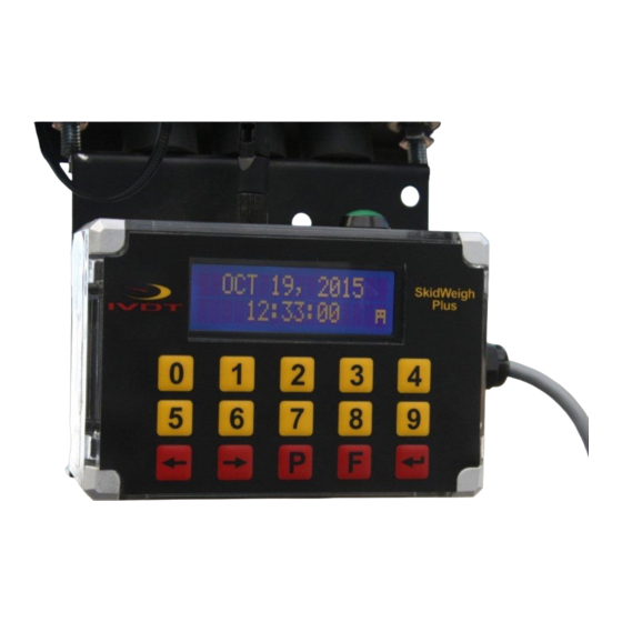
Electrical connections All SkidWeigh Plus systems operate from 12 to 55 VDC. - Orange Wire (+) Ignition switch - Brown Wire (-) Battery negative - Red Wire, connect to RED wire of the pressure transducer cable - Black Wire, connect to BLACK wire of the pressure transducer cable - White Wire, connect to WHITE wire of the pressure transducer cable Power short circuit protection All SkidWeigh systems are internally short circuit protected with resettable fuse. - Page 5 LCD Display Impact Monitoring Special Functions Button Bluetooth Icon Mounting Bracket With Anti Vibration Mounts Keypad Toggle Arrows Keys in set up menu “Enter key” ↵ Print key FUNCTION MODE KEY ADMINISTRATIVE MENU (Password protected) OPERATOR MENU (Bluetooth pairing, Tare input, Parts Count, etc. if applicable) Integrated Visual Data Technology Inc.
-
Page 6: Administrative Menu
Administrative Menu installation technician to calibrate system weighing function (Set The administration menu allows the Calibration 1), set the overload if applicable and for the end user to manage data, set vehicle ID#, input proper time and date, modify utilization factor, impacts set up menu and saving data to memory stick. Note: Data collected will depend on the hardware / software configuration. - Page 7 LCD Display MENU Password = ___ LCD Display <> KEY to SCROLL F KEY TO EXIT Date / Time Set Up LCD Display SET CLOCK ENTER TO SELECT LCD Display SET CLOCK AUTO _ Use left ◀ and right ▶ arrow key (bottom left side of the keypad) to change from AUTO to MANUAL date/ time set up.
- Page 8 LCD Display Aug 28, 2010 12:20:23 “Enter key” ↵ Press to confirm the setting. The cursor will automatically move to the next item to be changed ( Month, Day, Year, Hours, Minutes, Seconds). On the last correction, seconds item press “Enter key” ↵ to confirm new date / time set up.
- Page 9 Saving recorded data to USB memory stick The UTX SkidWeigh Plus system will allow you to download all recorded data onto a USB drive. Follow instructions shown on the LCD display This function is located in Administrative Menu. LCD Display <>...
- Page 10 Weighing scale function calibration Make sure that forks are on the ground and LCD display is showing time and date. LCD Display Aug 28, 2010 12:20:23 To enter into the Administration Menu, press F key and than press 9 key. Input password 521. LCD Display MENU Password = ___...
- Page 11 Pick up a known load weight and lower the loaded forks to the ground. Input into the system the known load weight (Our example is 2000) and press “Enter key” ↵ . The LCD display will show LCD Display CALIBRATION 1 LIFT LOAD Activate lift control valve and lift loaded forks just above the ground.
-
Page 12: Default Factory Set Up
Default Factory Set Up (Optional Function) - Low impact 6 G , visual and audio - Audio alarm set to 5 seconds - High Impact 12 G , visual and audio - Audio alarm set to 5 seconds - Optional audio alarm in continuous mode until reseted by supervisor - Utilization factor, default value set to 30 (End use programable) - Safety checklist start time 7:00 AM (End use programable) - Safety checklist time period 8 hours (End use programable, 8 or 12 hours) - Page 13 Lift Truck Operator Weighing Guide Loaded forks must be lowered to the ground LCD display must show date / time Lift the load approximately 2” off the ground. Do not use tilt, side shift or move vehicle during the weighing cycle Within few seconds LCD display will show the load weigh Integrated Visual Data Technology Inc.
Need help?
Do you have a question about the ED3-AT SkidWeigh Plus Series and is the answer not in the manual?
Questions and answers