
Related Manuals for Siemens SIPROTEC 6MU805


Summary of Contents for Siemens SIPROTEC 6MU805
- Page 1 Preface Contents Introduction SIPROTEC Functions Merging Unit Mounting and Commissioning 6MU805 Technical Data V4.03 Appendix Literature Manual Glossary Index C53000-G1140-C380-5...
- Page 2 , SICAM , and DIGSI are registered tions; nor does it change these. All obligations of Siemens AG are trademarks of Siemens AG. Other designations in this manual stated in the relevant contractual agreements. might be trademarks whose use by third parties for their own pur- Siemens AG reserves the right to revise this document from time to poses would infringe the rights of the owner.
- Page 3 Scope This manual applies to: Merging Unit 6MU805; firmware version V4.03. Siemens recommends installing DIGSI in Windows 7. The version of DIGSI is 4.90 SP1 or higher. Indication of Conformity...
- Page 4 Preface Additional Support For question about the system, please contact your Siemens sales partner. Support Our Customer Support Center provides a 24-hour service. Phone: +49 (180) 524-7000 Fax: +49 (180) 524-2471 E-mail: support.energy@siemens.com Training Courses Inquiries regarding individual training courses should be addressed to our Training Center:...
- Page 5 The equipment (device, module) may be used only for such applications as set out in the catalogs and the tech- nical description, and only in combination with third-party equipment recommended and approved by Siemens. Problem-free and safe operation of the product depends on the following: •...
- Page 6 Preface Typographic and Symbol Conventions The following text formats are used when literal information from the device or to the device appear in the text flow: Parameter Names Designators of configuration or function parameters which may appear word-for-word in the display of the device or on the screen of a personal computer (with operation software DIGSI), are marked in bold letters in monospace type style.
- Page 7 License Conditions provide for it you can order the source code of the Open Source Software from your Siemens sales contact - against payment of the shipping and handling charges - for a period of at least 3 years since purchase of the Product. We are liable for the Product including the Open Source Software contained in it pursuant to the license conditions applicable to the Product.
- Page 8 Open Source Software SIPROTEC, 6MU805, Manual C53000-G1140-C380-5, Release date 06.2018...
-
Page 9: Table Of Contents
Contents Introduction................9 Overall Operation. - Page 10 Contents Additional Functions ............. . . 40 2.3.1 Message Processing .
- Page 11 Contents Commissioning ..............94 3.3.1 Merging Unit Functionality .
- Page 12 Contents Settins ............... . . 141 Information List .
-
Page 13: Introduction
Introduction This chapter introduces the SIPROTEC Merging Unit (MU) 6MU805 and gives an overview of the device ap- plication, properties and functions. Overall Operation Application Scope Characteristics SIPROTEC, 6MU805, Manual C53000-G1140-C380-5, Release date 06.2018... -
Page 14: Overall Operation
1.1 Overall Operation Overall Operation The SIEMENS device 6MU805 is a stand-alone merging unit with KEMA-certified to the standard IEC 61850- 9-2 process bus. 6MU805 digitizes the output of conventional instrument transformers synchronous to a time- synchronization signal and then converts them to sampled value telegrams according to IEC 61850-9-2 stan- dard. - Page 15 Introduction 1.1 Overall Operation Microcomputer System Apart from processing the measured values, the microcomputer system (C) also executes the control func- tions. They especially include: • Filtering and preparation of the measured quantities • Continuous monitoring of the measured quantities •...
-
Page 16: Application Scope
Commissioning operational usage is similar to the other SIPROTEC4/DIGSI4 products. To ensure a continu- ously stable operation of Merging Unit, Siemens recommends disconnecting the DIGSI via switching it to off- line mode or exiting the DIGSI program after the 6MU805 device is configured. Additonally, a supervision of time signals is supported. -
Page 17: Characteristics
Introduction 1.3 Characteristics Characteristics General Properties • Powerful 32-bit microprocessor system • Complete digital processing and control of measured value, from the sampling and digitalization of the mea- sured quantities to close and trip decisions for the switchgear component • Complete galvanic and interference-free isolation of the internal processing circuits of the measurement, control and supply circuits of the system using instrument transformers, binary input and output modules, and DC and AC voltage converters •... - Page 18 Introduction 1.3 Characteristics SIPROTEC, 6MU805, Manual C53000-G1140-C380-5, Release date 06.2018...
-
Page 19: Functions
Functions This chapter describes the function available on the SIPROTEC device Merging Unit 6MU805. It shows the setting possibilities for the function. Information with regard to the determination of setting values as well as formulas, if required, are also provided. General Merging Unit Additional Functions... -
Page 20: General
Web Monitor. The procedure is set out in the SIPROTEC System Description. Caution! To ensure a continuously stable operation of Merging Unit, Siemens recommends disconnecting the DIGSI via switching it to offline mode or exiting the DIGSI program after the 6MU805 device is configured. - Page 21 Functions 2.1 General Note At delivery all passwords are set by default to 000000. More detailed information about the password, refer to the system manual. Note Settings and screenshots in following chapters are based on the choosed English Language in DIGSI. With differrent PC device languages, settings and information data are various.
-
Page 22: Settings
Functions 2.1 General Special Features Most settings are self-explanatory. The special cases are described as follows: At address 0369 VT Con Type, you can specify the connection type of the voltage inputs. If you are using normal voltage transformers, select CONVENTIONAL. With 0459 Syscon MU Configuration, you can define whether the communication parameter configured with System configurator or not. - Page 23 Functions 2.1 General Information Type of In- Comments formation HWTestMod IntSP Hardware Test Mode SynchClock IntSP_Ev Clock Synchronization >Time Synch SP_Ev >Synchronize Internal Real Time Clock >Reset LED >Reset LED >Test mode >Test mode >DataStop >Stop data transmission Device OK Device is Operational and Protecting Reset Device Reset Device...
-
Page 24: Power System Data 1
Functions 2.1 General 2.1.2 Power System Data 1 2.1.2.1 Description The device requires certain data regarding the network and substation so that it can adapt its functions to this data depending on the application. This may be, for instance, nominal data of the substation and measuring transformers, polarity and connection of the measured quantities, breaker properties (where applicable), etc. - Page 25 Functions 2.1 General Figure 2-1 Connection Principle for a Capacitive Voltage Measurement In addition to the bushing capacitances, the line and stray capacitances also affect the measured voltage fed to the protection device. These capacitances are primarily determined by the type and length of the connection line.
- Page 26 Functions 2.1 General with Primary voltage of phase x prim, Lx Voltage at the voltage input of the protection device sec, Lx Bushing capacitance of phase x D,Lx Line and stray capacitance of phase x S,Lx System frequency (50 Hz or 60 Hz) The following figure represents the above equation graphically.
- Page 27 Functions 2.1 General Internal Normalization of the Measured Voltages The capacitance values for the three voltage inputs are usually not identical. Then, voltages identical on the primary side are mapped differently at the voltage inputs. The measured voltages are normalized by the device so that the three phase-to-ground voltages can be correctly used in calculation (e.g.
-
Page 28: Settings
Functions 2.1 General Current Clipping Limit Ratio Address 0480 ClipC informs the ratio of the clipping limit of the instantaneous current to the rated primary voltage multiplied with a square root of two. For example “clip=20” applied with rated primary current of =500A means clipping will occur at ±14140A Primary currents with magnitude above the clipping... - Page 29 Functions 2.1 General Table 3: Settings for 3-phase Ratio Addr. Parameter Setting Options Default Setting Comments 0480 ClipC 1 .. 57 Clip Current Limit 0481 ClipV 1 .. 11 Clip Voltage Limit 0482 CurAccuClass 0.2/1 P 0.2/1 P Current Accuracy Class 0.2 S/1 P 0.5/1 P 0.5 S/1 P...
- Page 30 Functions 2.1 General Table 4: Settings for 1-phase Ratio Addr. Parameter Setting Options Default Setting Comments 0481 ClipV 1 .. 11 Clip Voltage Limit 0482 CurAccuClass 0.2/1 P 0.2/1 P Current Accuracy Class 0.2 S/1 P 0.5/1 P 0.5 S/1 P 1/1 P 0.2/5 P 0.2 S/5 P...
- Page 31 Functions 2.1 General Table 4: Settings for 1-phase Ratio Addr. Parameter Setting Options Default Setting Comments 0576 Ch4RatedPrimVol 0.10 .. 800.00 kV 20.00 kV Channel4 Rated Primary Voltage 0577 Ch4RatedSecVol 34.. 400 V 100 V Channel4 Rated Second Voltage For other settings belonging to Power System Data 1 and special for Merging Unit, please refer to chapter 2.2.2.
-
Page 32: Oscillographic Fault Records
Functions 2.1 General 2.1.3 Oscillographic Fault Records (Waveform Capture) The Merging Unit 6MU805 features a fault record memory. It is used for commissioning. It can be triggered by indications from GOOSE message, CFC and binary input. The instantaneous values for and v are sampled at intervals of 1.0 ms (at 50 Hz) and stored in a circular buffer (20 samples per cycle). -
Page 33: Setting Notes
Functions 2.1 General 2.1.3.2 Setting Notes Configuration Fault recording (waveform capture) will only take place if address 0104 OSC. FAULT REC. is set to Enabled. Other settings pertaining to fault recording (waveform capture) are found in the OSC. FAULT REC. submenu of the SETTINGS menu. -
Page 34: Setting Notes
Functions 2.1 General If the primary reference voltage and the primary reference current of the protected object are specified, the device can calculate and issue the percentage operational measured values. 2.1.4.2 Setting Notes Definition of Nominal Rated Values At addresses 1101 FullScaleVolt. and 1102 FullScaleCurr., the primary reference voltage (phase-to-phase) and reference current (phase) of the protected equipment is entered (e.g. -
Page 35: En100-Module
Functions 2.1 General 2.1.5 EN100-Module 2.1.5.1 Description The EN100-Module enables integration of the 6MU805 in 100-Mbit communication networks in control and au- tomation systems with the protocols according to IEC 61850 standard. This standard permits uniform commu- nication of the devices without gateways and protocol converters. Even when installed in heterogeneous envi- ronments, MU therefore provides for open and interoperable operation. -
Page 36: Merging Unit
Functions 2.2 Merging Unit Merging Unit The MU device 6MU805 fulfils to merge and synchronize currents and voltages in IEC61850-9-2 telegram ac- cording to IEC61869-9 modi (F4000S1I4U4, F4000S2I4U4, F4800S1I4U4, F4800S2I4U4) and distribute tele- grams via 2 optical Ethernet Interfaces. The device supports the following main functions: •... -
Page 37: Functional Description
Functions 2.2 Merging Unit 2.2.1 Functional Description Acquisision and Mergence of Multi-channel Data The MU device 6MU805 supports to digitize sample values of 4 currents (1 A/5 A) and 4 voltages (100 V/ 110 V) with 80 samples per cycle for 50 Hz or 60 Hz power grid systems. The device acquires and merges the sample values from instrument transfomers synchronnously. - Page 38 Functions 2.2 Merging Unit • parameter 0460 PPS Synchro is set to OFF, no matter time sync signal is received at the time sync interface • or the physical time sync signal is never received by 6MU805 Then the distributed IEC61850-9-2 SVs (sample values) are not synchronized to time sync signal and are flagged as not synchronized.
-
Page 39: Setting Notes
Functions 2.2 Merging Unit 2.2.2 Setting Notes The Merging Unit device 6MU805 offers two kinds of configurations of the communication parameters controlled by the parameter 0459 SysCon MU Configuration. If 0459 SysCon MU Configuration is set to Enabled, some of the following parameters are not displayed at device HMI and DIGSI4 and must be configured via the IEC61850 CID-File with the System-configurator (SysCon PC- tool). - Page 40 Functions 2.2 Merging Unit At Address 0455A OptFlds refTime information, it is checked whether the field refresh time is contained in IEC61850-9-2 telegram. At Address 0456A OptFlds sam-syn, it is checked whether the field smpSynch is contained in IEC61850-9-2 telegram At Address 0457A OptFlds samrate, it is checked whether the field smpRate is contained in IEC61850-9-2 tele- gram.
-
Page 41: Settings
Functions 2.2 Merging Unit 2.2.3 Settings Addr. Parameter Setting Options Default Comments Setting 0407 VLAN ID 0...4095 dec 1 dec VLAN ID 0408 VLAN Priority 1...7 dec 4 dec VLAN Priority 0 μs, 0.1s...5000.0 s 0.0 μs 0438 PPS Delay PPS Delay 0460 PPS Synchro... - Page 42 Functions 2.2 Merging Unit Addr. Parameter Setting Options Default Comments Setting 0489 DestMac Addr4 0...255 dec 4 dec DestMACAddr Byte4 0490 DestMac Addr5 0...255 dec 0 dec DestMACAddr Byte5 0491 DestMac Addr6 0...255 dec 0 dec DestMACAddr Byte6 0492 Application ID 16384...32767 16384 dec Application ID...
-
Page 43: Information List
Functions 2.2 Merging Unit 2.2.4 Information List Information Type of Information Comments 31010 >VTMCB aux Cont Indication of voltage fuse failure 31011 SV global sync SV global synchronized 31013 PPS lost PPS lost 31014 SV local sync SV local synchronized 31015 SV not sync SV not synchronized... -
Page 44: Additional Functions
Functions 2.3 Additional Functions Additional Functions The general functions of the device are described in the following sections. 2.3.1 Message Processing After the occurrence of a system fault, information regarding the response of the protective relay and the mea- sured values is important for a detailed analysis. An information processing function in the device takes care of this. -
Page 45: Information Via Display Panel Or Pc
Functions 2.3 Additional Functions 2.3.1.2 Information via Display Panel or PC Events and conditions can be read from the display panel of the Web Monitor. A PC to which the information is then sent can be connected via the USB interface or port F of the device. The device is equipped with several event buffers for operational indications, circuit breaker statistics etc., which are protected against loss of the auxiliary voltage by a buffer battery. -
Page 46: Information List
Functions 2.3 Additional Functions 2.3.2.1 Information List Information Type of Information Comments 1020 Op.Hours= Counter of operating hours 2.3.3 Measurement A series of measured values and values derived from these are constantly available for call-up by the Web Monitor, or for data transfer.The main propose of the measured values in the MU is to support the commissio- ning. - Page 47 Functions 2.3 Additional Functions Measured values Secondary Primary sec. = 3 ·I N sec. (calculated) = measured value N sec. from the I input ph-n sec. A–B B–C ph-ph ph-ph sec. sec.C–A P, Q, S (P and Q No secondary measured values phase-segregated) cos ...
-
Page 48: Transmitting Measured Values
Functions 2.3 Additional Functions same applies to the power factor cos. It is occasionally desired to define the power drawn from the line (e.g. as seen from the consumer) positively. Using parameter 1108 P,Q sign the signs for these components can be inverted. -
Page 49: Commissioning Aids
Functions 2.3 Additional Functions Information Type of Information Comments 2162 SysTemp = System Temperature 2233 Ux = Ux = 2241 LON = GPS Module Position Longitude (deg, dec) 2242 LAT = GPS Module Position Latitude (deg, dec) 2243 ALT = GPS Module Position Altitude (m) 30701 P,L1... - Page 50 Functions 2.3 Additional Functions Fault records that are triggered externally are processed by the device as a normal oscillographic records. For each oscillographic record a fault record is created, with an individual number to ensure that assignment can be made properly. The procedure is described in detail in Chapter "Mounting and Commissioning".
-
Page 51: Command Processing
Functions 2.4 Command Processing Command Processing A control command function is integrated in the 6MU805 device to coordinate the switching operations in the substation. Control commands can originate from four command sources: • Operation using the Web Monitor • Operation using DIGSI •... -
Page 52: Information List
Functions 2.4 Command Processing Operation Using an Interface Switchgear can also be controlled using a connection to the substation control system. For that, the required periphery must exist in the device and in the substation. Furthermore, certain settings for the interface need to be made in the device (see SIPROTEC 4 System Description/1/). -
Page 53: Command Sequence
Functions 2.4 Command Processing 2.4.3 Command Sequence Safety mechanisms in the command sequence ensure that a command can only be released after a thorough check of preset criteria has been successfully concluded. Standard Interlocking checks are provided for each individual control command. Additionally, user-defined interlocking conditions can be programmed separately for each command. -
Page 54: Switchgear Interlocking
Functions 2.4 Command Processing 2.4.4 Switchgear Interlocking System interlocking is executed by the user-defined logic (CFC). 2.4.4.1 Description Interlocking checks in a SICAM / SIPROTEC 4 system are normally divided in the following groups: • System interlocking relies on the system data base in the substation or central control system. •... - Page 55 Functions 2.4 Command Processing The check of interlocking can be programmed separately for all switching devices and tags that were set with a tagging command. Other internal commands such as manual entry or abort are not checked, i.e. carried out independently of the interlocking.
- Page 56 Functions 2.4 Command Processing Figure 2-5 Standard interlockings Note The merging unit 6MU805 additionally features a service interlocking function for blocking switching commands for selected switches. For more details, see the following margin heading ”Service Interlocking”. The following figure shows the configuration of the interlocking conditions using DIGSI. SIPROTEC, 6MU805, Manual C53000-G1140-C380-5, Release date 06.2018...
- Page 57 Functions 2.4 Command Processing Figure 2-6 DIGSI Dialog Box 'Object Properties' for Setting the Interlocking Conditions With the Web Monitor, configured interlocking causes are output on the device display. They are marked by letters explained in the following table. Table 2-2 Command types and corresponding messages Interlocking Commands Abbrev.
- Page 58 Functions 2.4 Command Processing Switching Authority The interlocking condition "Switching authority" serves for determining the switching authority. It enables the user to select the authorized command source. The following switching authority ranges are defined in the fol- lowing priority sequence: •...
- Page 59 Functions 2.4 Command Processing Switching Mode The switching mode serves for activating or deactivating the configured interlocking conditions at the time of the switching operation. The following (local) switching modes are defined: • For local commands (CS = LOCAL) - interlocked (normal) or - unlocked (non-interlocked) With a 6MU805, the switching mode can be changed between "interlocked"...
- Page 60 Functions 2.4 Command Processing condition equals actual condition". If the circuit breaker / switchgear device is in the intermediate position, then this check is not performed. Bypassing Interlocking Bypassing configured interlockings at the time of the switching action happens device-internally via interlocking recognitions in the command job or globally via so-called switching modes.
- Page 61 Functions 2.4 Command Processing Figure 2-7 Service Interlocking, Example of Internal Interlocking, External, and Binary Input You can connect the signals and indications in the routing matrix as desired, for example to the LEDs of the operation panel or for transmitting or receiving data over the system interface. The following figure shows an example for routing the information.
-
Page 62: Command Logging
Functions 2.4 Command Processing Figure 2-8 Service Interlocking, Example for Routing to LEDs The service interlocking indications are logged in the operational log. 2.4.5 Command Logging During the processing of the commands, independent of the further message routing and processing, command and process feedback information are sent to the message processing center. - Page 63 Functions 2.4 Command Processing Acknowledgment of Commands to LOCAL/REMOTE/DIGSI The acknowledgment of indications with source of command LOCAL/REMOTE/DIGSI are sent back to the ini- tiating point independent of the routing (configuration on the interface). The acknowledgment of commands is thus not effected via a response as in the case of a local command but via the normal command and feedback logging.
- Page 64 Functions 2.4 Command Processing Monitoring of Feedback Information The processing of commands monitors the command execution and timing of feedback information for all com- mands. At the same time the command is sent, the monitoring time is started (monitoring of the command ex- ecution).
-
Page 65: Device Operation
Functions 2.5 Device Operation Device Operation The optional operation panel and the Web Monitor allow displaying parameters, indications and measured values of the 6MU805 during operation or commissioning. The Web Monitor is started in a web browser such as Internet Explorer. Apart from general information regarding installation, this manual provides a description of specific functions of the Web Monitor for 6MU805 only. - Page 66 • The Information display field shows device information, connection states and access rights. Via the menu bar, you can select all logs and measured values displayed in the navigation tree. The menu item Options is used for diagnostic purposes and can be activated by Siemens experts only. SIPROTEC, 6MU805, Manual...
- Page 67 Functions 2.5 Device Operation Control and Display Panel The control and display panel is structured into various function and display areas. • 32 LEDs to display operating states or indications • O and C key to activate/deactivate assigned operational equipment LOSE •...
- Page 68 Functions 2.5 Device Operation Displaying of Indications In the Web Monitor, the indications of the 6MU805 are displayed in different logs depending on their type and allocation. • Event Log • Trip Log • Earth Log • Spontaneous Log • Fault Records The list selected in the navigation tree is shown in the display area.
- Page 69 Functions 2.5 Device Operation Figure 2-11 Web Monitor – Operational Indications SIPROTEC, 6MU805, Manual C53000-G1140-C380-5, Release date 06.2018...
- Page 70 Functions 2.5 Device Operation Figure 2-12 Web Monitor – Fault Indication The Fault Records overview shows all active fault records. Click the V key to open the fault record in the SIGRA evaluation program. SIGRA must be installed on your system.
- Page 71 Functions 2.5 Device Operation Figure 2-13 Web Monitor – Fault Record Overview Displaying Measured Values In the Web Monitor, the measured values and count values of the 6MU805 are displayed in various lists. • Primary values Measured values of the primary side •...
- Page 72 Functions 2.5 Device Operation Figure 2-14 Web Monitor – Primary Measured Values Logging The following screenshot is an example of a measurement log saved as text file. The event logs have a similar layout. Figure 2-15 Measurement log example SIPROTEC, 6MU805, Manual C53000-G1140-C380-5, Release date 06.2018...
-
Page 73: Operation Panel Of The Device
Functions 2.5 Device Operation 2.5.2 Operation Panel of the Device The merging unit 6MU805 is available with or without operation panel. The operation panel can be permanently attached to the 6MU805 or it can be detached. All functions described in the previous Web Monitor section can also be executed via the operation panel. The Web Monitor is a complete emulation of the device display. - Page 74 Functions 2.5 Device Operation SIPROTEC, 6MU805, Manual C53000-G1140-C380-5, Release date 06.2018...
-
Page 75: Mounting And Commissioning
Mounting and Commissioning This chapter is intended for experienced commissioning staff. The staff must be familiar with the commissioning of control systems, with power systems management and with the relevant safety rules and guidelines. Under certain circumstances, it may become necessary to adapt parts of the power system hardware. Some of the primary tests require the protected line or equipment to carry load. -
Page 76: Mounting And Connections
The rated device data have been checked as recommended in the SIPROTEC 4 System Description/1/. It has been verified that these data comply with the power system data.Siemens recommends installing DIGSI in Windows 7. The version of DIGSI is 4.90 SP1 or higher. - Page 77 Mounting and Commissioning 3.1 Mounting and Connections dependent on this configuration. The presettings of the device are listed in Appendix A.5. Please also check that the labeling strips on the front panel correspond to the configured message functions. SIPROTEC, 6MU805, Manual C53000-G1140-C380-5, Release date 06.2018...
-
Page 78: Hardware Modifications
Mounting and Commissioning 3.1 Mounting and Connections 3.1.2 Hardware Modifications 3.1.2.1 Disassembly Replacing the Buffer Battery The battery is located in a battery compartment which is accessible from outside. The battery compartment can be found on the side of the device. When replacing the battery, it is not necessary to open the device. In the case of a failure of the auxiliary voltage, the battery ensures operation of the internal clock and storage of all process data for at least half a year. - Page 79 Any service activities exceeding the installation or exchange of com- munication modules must only be carried out by Siemens personnel. For preparing the workplace, a pad suitable for electrostatic sensitive devices (ESD) is required.
- Page 80 Mounting and Commissioning 3.1 Mounting and Connections Unscrew all screws with which the cover is fixed to the device. Remove the protective cap of the GPS antenna, if any. Now carefully remove the housing. Figure 3-2 Housing SIPROTEC, 6MU805, Manual C53000-G1140-C380-5, Release date 06.2018...
- Page 81 Make sure that the defective fuse has not left any obvious damage on the device. If the fuse trips again after reconnection of the device, refrain from any further repairs and send the device to Siemens for repair. The device can now be reassembled again (see Section Reassembly).
-
Page 82: Current Terminal Connections
Mounting and Commissioning 3.1 Mounting and Connections 3.1.2.2 Current Terminal Connections Stop Elements and Cable Cross-Sections Figure 3-4 8-pin current terminal Ring and fork-type lugs can be used for the connection. For complying with the required insulation clearances, insulated lugs have to be used. Otherwise, the crimp zone has to be insulated with corresponding means (e.g. by pulling a shrink-on sleeve over). -
Page 83: Process Terminal Connections
The ordering data is specified in Appendix A1. Solid conductors as well as stranded conductors with or without conductor sleeves can be used as single cables. Siemens recommends using twin cable end sleeves when connecting two single cables. Cable cross-sections: AWG 26-12 (0.2 mm... -
Page 84: Interface Modules
Mounting and Commissioning 3.1 Mounting and Connections 3.1.2.4 Interface Modules General The 6MU805 device is supplied with preconfigured interfaces in accordance with the MLFB. You do not have to make any adaptations to the hardware (e.g. plugging in jumpers) yourself, except for the installation or re- placement of communication modules. -
Page 85: Installation
Mounting and Commissioning 3.1 Mounting and Connections 3.1.3 Installation 3.1.3.1 General To install the 6MU805 device in a rack or cabinet, the two mounting brackets included in the delivery are re- quired. Figure 3-7 Device view SIPROTEC, 6MU805, Manual C53000-G1140-C380-5, Release date 06.2018... - Page 86 Mounting and Commissioning 3.1 Mounting and Connections Housing Assembly • Fix the device to the mounting brackets with 4 screws. • Loosely screw the two mounting brackets into the rack or cabinet with 4 screws each. • Tighten the 8 screws of the mounting brackets in the rack or cabinet. •...
-
Page 87: Hmi (Human-Machine Interface) Optional
Mounting and Commissioning 3.1 Mounting and Connections 3.1.3.2 HMI (Human-Machine Interface) Optional You can operate the 6MU805 device by using the Web Monitor or directly via the optional HMI. The HMI inter- face of 6MU805 resues the HMI interfaces of 7SC80. You can mount the HMI either directly on the 6MU805 or detached and connected via cable. - Page 88 Mounting and Commissioning 3.1 Mounting and Connections Figure 3-9 Panel Cutout for Variant with Attached HMI SIPROTEC, 6MU805, Manual C53000-G1140-C380-5, Release date 06.2018...
- Page 89 Mounting and Commissioning 3.1 Mounting and Connections Figure 3-10 Panel Cutout with Adhesive Sealing Glue the 2 parts of the flat gasket aligned from behind on the panel cut-out. SIPROTEC, 6MU805, Manual C53000-G1140-C380-5, Release date 06.2018...
- Page 90 Mounting and Commissioning 3.1 Mounting and Connections Figure 3-11 Variant with Detached HMI Note You can connect or remove the HMI during device operation (hot pluggable). Note If you connect the HMI to the device via cable, use the USB port of the HMI. SIPROTEC, 6MU805, Manual C53000-G1140-C380-5, Release date 06.2018...
- Page 91 Mounting and Commissioning 3.1 Mounting and Connections Figure 3-12 Panel Cutout for Variant with Detached HMI SIPROTEC, 6MU805, Manual C53000-G1140-C380-5, Release date 06.2018...
- Page 92 Mounting and Commissioning 3.1 Mounting and Connections Figure 3-13 Panel Cutout with Adhesive Sealing SIPROTEC, 6MU805, Manual C53000-G1140-C380-5, Release date 06.2018...
- Page 93 Mounting and Commissioning 3.1 Mounting and Connections Figure 3-14 Panel with Detached HMI Attaching the HMI at the device, at the front side of the frame or at the mounting plate. Screw Length 10 mm (attached HMI) longer screws are permitted only with detached HMI Permissible tightening torque at the screw 0.6 Nm...
-
Page 94: Checking Connections
Mounting and Commissioning 3.2 Checking Connections Checking Connections 3.2.1 Checking the Data Connections of the Interfaces Pin Assignment The following tables show the pin assignment of the various interfaces. The position of the connections can be seen in the following figures. Figure 3-16 9-pin D-sub socket (HMI) Figure 3-17... - Page 95 Mounting and Commissioning 3.2 Checking Connections The optional HMI is connected via the 9-pin D-SUB socket. Table 3-1 Socket Assignment Pin No. Function USB D+ DET_HMI USB D- USB Interface The USB interface can be used to establish a connection between the merging unit and your PC. For the com- munication, the Microsoft Windows USB driver is used which is installed together with DIGSI (as of version V4.90 SP1 or higher).
-
Page 96: Checking The System Connections
Mounting and Commissioning 3.2 Checking Connections Checking the Time Synchronization Interface When connecting the time signal transmitter (GPS and IRIG-B), the specified technical data must be observed (see Chapter 4 Technical Data, 4.1.4). The GPS suplies UTC time and the IRIG-B module supplies time without the time zone and switchover to/from daylight-saving time. - Page 97 Mounting and Commissioning 3.2 Checking Connections Caution! Take care when operating the device without a battery on a battery charger. Non-observance of the following measures can lead to unusually high voltages and consequently, the destruc- tion of the device. Do not operate the device on a battery charger without a connected battery. (For limit values see also Technical Data, Section 4.1).
-
Page 98: Commissioning
Mounting and Commissioning 3.3 Commissioning Commissioning WARNING! Warning of dangerous voltages when operating an electrical device Non-observance of the following measures can result in death, personal injury or substantial property damage. Only qualified people shall work on and around this device. They must be thoroughly familiar with all warnings and safety notices in this instruction manual as well as with the applicable safety steps, safety regulations, and precautionary measures. - Page 99 Mounting and Commissioning 3.3 Commissioning connected via P2P (point to point), HSR (High Speed Redundacy) or PRP (Parallel Redundacy Protocol). Basic configurations of the Ethernet connection is explained in the SIPROTEC 4 System Description /1/. Moreover, further configurations special are for the IEC61850-9-2 SV-telegram such as Destination MAC ad- dress, APPID, VLAN, SV-ID.
-
Page 100: Test Mode And Transmission Block
Mounting and Commissioning 3.3 Commissioning The recommended configuration is Set by MU, if the SV-subscriber supports the corresponding quality bit. If only “False” is offered, the IEC61869 doesn’t support this quality bit. Parameter 0485 IEC61850Ed2Sync determinesthe local-area clock identifier in IEC61850-9-2 Edition 2 SV telegrams when 6MU805 is local synchronized. - Page 101 Mounting and Commissioning 3.3 Commissioning Note After termination of the system interface test the device will reboot. Thereby, all annunciation buffers are erased. If required, these buffers should be extracted with DIGSI prior to the test. The interface test is carried out using DIGSI in the Online operating mode: •...
-
Page 102: Communication Module Configuration
Mounting and Commissioning 3.3 Commissioning Test in Message Direction For all information that is transmitted to the central station, test the options in the list which appears in SET- POINT Status: • Make sure that each checking process is carried out carefully without causing any danger (see above and refer to DANGER!) •... -
Page 103: Checking The Status Of Binary Inputs And Outputs
Mounting and Commissioning 3.3 Commissioning 3.3.5 Checking the Status of Binary Inputs and Outputs Prefacing Remarks The binary inputs, outputs, and LEDs of the 6MU805 can be individually and precisely controlled in DIGSI. This feature is used to verify control wiring from the device to plant equipment (operational checks) during commis- sioning. - Page 104 Mounting and Commissioning 3.3 Commissioning Figure 3-23 Test of the binary inputs/outputs — example Changing the Operating State To change the status of a hardware component, click on the associated button in the Scheduled column. Password No. 6 (if activated during configuration) will be requested before the first hardware modification is allowed.
- Page 105 Mounting and Commissioning 3.3 Commissioning Proceed as follows in order to check the binary inputs: • Activate each of function in the system which causes a binary input to pick up. • Check the reaction in the Status column of the dialog box. To do so, the dialog box must be updated. The options may be found below under the margin heading „Updating the Display“.
-
Page 106: Current, Voltage Testing
Mounting and Commissioning 3.3 Commissioning 3.3.6 Current, Voltage Testing Preliminary Remark Note The voltage and phase rotation test is only relevant for devices with voltage transformers. 10 % of Load Current The connections of the current and voltage transformers are tested using primary quantities. Secondary load current of at least 10 % of the nominal current of the device is necessary. -
Page 107: Switching Test For Configured Equipment
Mounting and Commissioning 3.3 Commissioning 3.3.7 Switching Test for Configured Equipment Switching via Command Input If the configured equipment was not switched sufficiently in the hardware test , configured equipment must be switched on and off from the device via the integrated control element. The feedback information on the circuit breaker position injected via binary inputs is to be read out at the device and compared with the actual breaker position. -
Page 108: Creating A Test Fault Record
Mounting and Commissioning 3.3 Commissioning 3.3.8 Creating A Test Fault Record In order to test the stability of the protection during switch-on procedures also, switch-on trials can also be carried out at the end. Oscillographic records obtain the maximum information about the behavior of the pro- tection. -
Page 109: Final Preparation Of The Device
PC. Caution! To ensure a continuously stable operation of Merging Unit, Siemens recommends disconnecting the DIGSI via switching it to offline mode or exiting the DIGSI program after the 6MU805 device is configured. Check the internal clock of the device. If necessary, set the clock or synchronize the clock if it is not synchro- nized automatically. - Page 110 Mounting and Commissioning 3.4 Final Preparation of the Device SIPROTEC, 6MU805, Manual C53000-G1140-C380-5, Release date 06.2018...
-
Page 111: Technical Data
Technical Data This chapter provides the technical data of the device SIPROTEC 6MU805 and its individual functions, includ- ing the limit values that may not be exceeded under any circumstances. The electrical and functional data for the maximum functional scope are followed by the mechanical specifications with dimensioned drawings. -
Page 112: General Device Data
Technical Data 4.1 General Device Data General Device Data 4.1.1 Analog Inputs Current Inputs Standard: Nominal frequency 50 Hz 60 Hz Frequency operating range GPS MU 49 Hz to 51 Hz 58.5 Hz to 61.5 Hz PPS MU 40 Hz to 70 Hz (independent of the nominal frequency) Nominal current 1 A or 5 A... -
Page 113: Auxiliary Voltage
220 V induced above 220 nF at a recovery time between two switching operations 60 ms For plants where a high EMC load is expected at the binary inputs, Siemens recommends setting the filtering time to 5 ms. SIPROTEC, 6MU805, Manual... -
Page 114: Communication Interfaces
Technical Data 4.1 General Device Data Output Relays Signal/command relay, alarm relay Quantity and data 6MU805 8 BO Switching capability CLOSE 1000 W / 1000 VA 40 W or 30 VA at L/R 40 ms Switching capability TRIP Switching voltage AC and DC 250 V Permissible current per contact (continuous) Permissible current per contact (close and hold) -
Page 115: Electrical Tests
Technical Data 4.1 General Device Data PPS/IRIG-B Connection multimode optical fiber G50 m/125 m, G62.5m/125 m 4.1.5 Electrical Tests Regulations Standards: see also individual tests Merging unit Bay units IEC 60255 IEC 60870 EN 60255/EN 50263 EN 60870 DIN 57435/DIN EN 50263 DIN EN 60870 IEC TS 61000-6-5 IEC TS 61000-6-5... -
Page 116: Mechanical Tests
Technical Data 4.1 General Device Data Irradiation with amplitude-modulated HF field, class 10 V/m; 80 MHz to 2.7 GHz 80 % AM; 1 kHz IEC 60255-22-3, IEC 61000-4-3 Fast transient disturbance variables/burst, class IV 4 kV; 5 ns/50 ns; 5 kHz; burst length = 15 ms; repetition = 50 ;... - Page 117 10 g, duration 16 ms, IEC 60068-2-29 1000 shocks in each direction of the 3 orthogonal axes After long shock stress, Siemens recommends checking the screw fastening and tightening it if necessary. SIPROTEC, 6MU805, Manual C53000-G1140-C380-5, Release date 06.2018...
-
Page 118: Climatic Stress Tests
30 days of the year up to 95 % relative humidity; condensation must be avoided! Siemens recommends installing the devices in a place where they are not exposed to direct sunlight or great temperature variations that could lead to condensation. -
Page 119: Constructive Design
Technical Data 4.1 General Device Data 4.1.9 Constructive Design Dimensions See dimensional drawings, Section 4.4 Device Housing Weight 6MU805 For panel flush mounting and panel surface mounting 3.6 kg 1.4 kg Degree of protection in acc. with IEC 60529 For equipment in surface-mounting housing or flush- IP 40 mounting housing For operator protection... -
Page 120: Additional Functions
Technical Data 4.2 Additional Functions Additional Functions Sampled Measured Values Currents in A (kA) primary and in A secondary or in % I or 3I0 Range 10 % I < I <200 % I Norm Tolerance 0.2 % of measured value or 0.2 % I Voltages (phase-to-ground) in kV primary, in V secondary or in % V Norm... - Page 121 Technical Data 4.2 Additional Functions Operational Measured Values For Commissioning Currents in A (kA) primary and in A secondary or in % I Positive sequence component I Negative sequence component I or 3I0 Range 10 % to 150 % I Tolerance 1.5 % of measured value or 1 % I and from 151 % to 200 % I...
- Page 122 Technical Data 4.2 Additional Functions Fault Recording max. 8 fault records saved by buffer battery also in the event of auxiliary voltage failure Storage period 6 s per fault record, in total up to 18 s at 50 Hz (max. 15 s at 60 Hz) Sampling rate at 50 Hz each 1 instantaneous value per 1.0 ms Sampling rate at 60 Hz...
-
Page 123: User-Defined Functions (Cfc)
Technical Data 4.3 User-defined Functions (CFC) User-defined Functions (CFC) Function Blocks and Their Possible Assignments to Task Levels Function block Explanation Task level PLC1_ PLC_ SFS_ BEARB BEARB BEARB BEARB ABSVALUE Magnitude Calculation — — — Addition ALARM Alarm AND - Gate BLINK Blink block BOOL_TO_CO... - Page 124 Technical Data 4.3 User-defined Functions (CFC) Function block Explanation Task level PLC1_ PLC_ SFS_ BEARB BEARB BEARB BEARB LIVE_ZERO — — — LONG_TIMER Timer (max.1193h) LOOP Feedback Loop — LOWER_SETPOINT Lower Limit — — — MAN_CBOp Circuit breaker trip — Multiplication MVU_GET_STATUS Decode status of a...
- Page 125 Technical Data 4.3 User-defined Functions (CFC) Device-Specific CFC Blocks Table 4-1 ASWITCH – This block is used to switch between two REAL inputs (RMS values). Name Type Description Default function Input SWITCH BOOL Analog value selection FALSE REAL Analog value REAL Analog value Output...
- Page 126 Technical Data 4.3 User-defined Functions (CFC) Additional Limits Additional limits for the following CFC blocks: Task Level Maximum Number of Modules in the Task Levels 2) 3) 2) 3) TIMER TIMER_SHORT MW_BEARB — — PLC1_BEARB PLC_BEARB SFS_BEARB — — When the limit is exceeded, an error message is iisued by the device. Consequently, the device starts mon- itoring.
- Page 127 Technical Data 4.3 User-defined Functions (CFC) Processing Times in TICKS for the Individual Elements Individual element Number of TICKS Block, basic requirement Each input more than 3 inputs for generic modules Combination with input signal border Combination with output signal border Additionally for each chart Arithmetic ABS_VALUE...
- Page 128 Technical Data 4.3 User-defined Functions (CFC) Individual element Number of TICKS Type converter BOOL_TO_DI BUILD_DI DI_TO_BOOL DM_DECODE DINT_TO_REAL DIST_DECODE UINT_TO_REAL REAL_TO_DINT REAL_TO_UINT Comparison COMPARE LOWER_SETPOINT UPPER_SETPOINT LIVE_ZERO ZERO_POINT Integrated total COUNTER Time and clock pulse TIMER TIMER_LONG TIMER_SHORT ALARM BLINK Other COMMS_CHK Diff87L...
-
Page 129: Dimensions
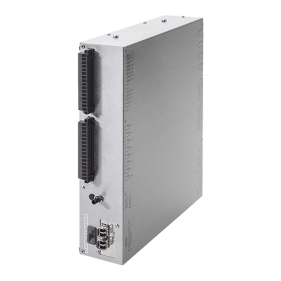
Technical Data 4.4 Dimensions Dimensions 4.4.1 Merging Unit 6MU805 Figure 4-1 Dimensional Drawing of an Merging Unit 6MU805 SIPROTEC, 6MU805, Manual C53000-G1140-C380-5, Release date 06.2018... -
Page 130: Hmi
Technical Data 4.4 Dimensions 4.4.2 Figure 4-2 Dimensional Drawing of an 6MU805 HMI ■ SIPROTEC, 6MU805, Manual C53000-G1140-C380-5, Release date 06.2018... -
Page 131: Appendix
Appendix This appendix is primarily a reference for the experienced user. This section provides ordering information for the models of this device. Connection diagrams indicating the terminal connections of the models of this device are included. Following the general diagrams are diagrams that show the proper connections of the devices to primary equipment in many typical power system configurations. -
Page 132: Ordering Information And Accessories
Appendix A.1 Ordering Information and Accessories Ordering Information and Accessories A.1.1 Ordering Information 10 11 12 13 14 15 16 Suffix Merging Unit – – Basic functions, BO/BI Pos. 6 Housing, 12 BI, 8 BO, 1 life status contact Current and voltage inputs, default settings (BOLD) Pos. -
Page 133: Accessories
Appendix A.1 Ordering Information and Accessories Function package Pos. 15 Merging Unit Function package Pos. 16 None A.1.2 Accessories 6MU805 HMI without cable C53207-A406-D242-1 6MU805 HMI with cable C53207-A406-D243-1 6MU805 HMI cable kit C53207-A377-B701-1 Terminals Current terminal (set of 10 pieces) C53207-A406-D237-1 Process terminal 16-pin, (set of 18 pieces for cabinet surface mounting) C53207-A406-D238-1... -
Page 134: Terminal Assignments
Appendix A.2 Terminal Assignments Terminal Assignments A.2.1 6MU805 — Housing for Cabinet Flush Mounting and Cabinet Surface Mounting 6MU805 Figure A-1 Overview Diagram of 6MU805 SIPROTEC, 6MU805, Manual C53000-G1140-C380-5, Release date 06.2018... -
Page 135: Connection Examples
Appendix A.3 Connection Examples Connection Examples Figure A-2 Current transformer connections to three current transformers and neutral point current (ground current) (Holmgreen connection) – appropriate for all networks Figure A-3 Current transformer connections to two current transformers – only for isolated or resonant-grounded networks SIPROTEC, 6MU805, Manual C53000-G1140-C380-5, Release date 06.2018... - Page 136 Appendix A.3 Connection Examples Figure A-4 Current transformer connections to three current transformers, ground current from an additional summation current transformer – preferably for effectively or low-resistance grounded networks Important: Grounding of the cable shield must be effected at the cable side Note: The switchover of the current polarity (address 201) also reverses the polarity of the current input IN! Figure A-5...
- Page 137 Appendix A.3 Connection Examples Figure A-6 Transformer connections to three current transformers and three voltage transformers – capacitive SIPROTEC, 6MU805, Manual C53000-G1140-C380-5, Release date 06.2018...
-
Page 138: Current Transformer Requirements
Appendix A.4 Current Transformer Requirements Current Transformer Requirements The current transformer requirements should follow the requirements of the bay level equipment. And the MU provides the configuration "Accuracy Class", which is distributed to the bay level equipment via IEC61850 Edition2 ICD file. For more details about accuracy class please refer to chapter A.8 . SIPROTEC, 6MU805, Manual C53000-G1140-C380-5, Release date 06.2018... -
Page 139: Default Settings
Appendix A.5 Default Settings Default Settings When the device leaves the factory, many LED indications, binary inputs, binary outputs and function keys are already preset. They are summarized in the following table. A.5.1 LEDs Table A-1 LED Display, e.g. Via the Web-Monitor LEDs Default function Function No. -
Page 140: Binary Input
Appendix A.5 Default Settings A.5.2 Binary Input Table A-2 Binary input presettings for all devices and ordering variants Binary Input Default function Function No. Description not pre-assigned >Brk Aux NC 4602 >Breaker contact(OPEN, if breaker is closed) Breaker Breaker >Brk Aux NO 4601 >Breaker contact(OPEN, if breaker is open) Breaker... -
Page 141: Function Keys
Appendix A.5 Default Settings A.5.4 Function Keys Table A-4 The called functions are executed directly, e.g. via the Web-Monitor, without any feedbacks (one-push-button). Function Keys Default function not pre-assigned not pre-assigned not pre-assigned not pre-assigned not pre-assigned not pre-assigned not pre-assigned not pre-assigned not pre-assigned SIPROTEC, 6MU805, Manual... -
Page 142: Default Display
Appendix A.5 Default Settings A.5.5 Default Display A number of pre-defined measured value pages are available depending on the device type. The start page of the default display appearing after startup of the device can be selected in the device data via parameter 0640 Start image DD. -
Page 143: Protocol-Dependent Functions
Appendix A.6 Protocol-dependent Functions Protocol-dependent Functions Protocol IEC 61850-9-2/IEC 61850-8-1 GOOSE Function Sample Values GOOSE Operational measured values Count values Fault recording Remote protection setting User-defined indications and switching objects Time synchronization Indications with time stamp Commissioning aids GOOSE stop SV stop Data transmission stop... -
Page 144: Functional Scope
Appendix A.7 Functional Scope Functional Scope Addr. Parameter Setting Options Default Setting Comments 0104 OSC. FAULT REC. Disabled Disabled Oscillographic Fault Records Enabled 0459 SysConMUConf Enabled Disabled MU Configuration via Disabled IEC61850 Configurator 0461 PhaseIndepRatio Enabled Disabled Phase Independent Ratio Disabled SIPROTEC, 6MU805, Manual C53000-G1140-C380-5, Release date 06.2018... -
Page 145: Settins
Appendix A.8 Settings Settings Addresses which have an appended "A" can only be changed with DIGSI, under "Display Additional Settings". The table indicates region-specific default settings. Column C (configuration) indicates the corresponding sec- ondary nominal current of the current transformer. Addr. - Page 146 Appendix A.8 Settings Addr. Parameter Function Setting Options Default Setting Comments 0446A Inconsi Quality Merging Unit False False Quality bit: Inconsistent 0447A Inaccu Quality Merging Unit Set By MU Set By MU Quality bit: Inaccurate True (Options True and False for test purpose) False 0448A Test Quality...
- Page 147 Appendix A.8 Settings Addr. Parameter Function Setting Options Default Setting Comments 0572 Ch2RatedPrimVol P.System Data 1 0.10 .. 800.00 kV 20.00 kV Channel2 Rated Primary Voltage 0573 Ch2RatedSecVol P.System Data 1 34.. 400 V 100 V Channel2 Rated Second Voltage 0574 Ch3RatedPrimVol P.System Data 1...
-
Page 148: Information List
Appendix A.9 Information List Information List In columns “Event Log”, “Trip Log” and “Ground Fault Log” the following applies: UPPER CASE NOTATION “ON/OFF”: definitely set, not allocatable lower case notation “on/off”: preset, allocatable not preset, allocatable <blank>: neither preset nor allocatable In the column „Marked in Oscill. - Page 149 Appendix A.9 Information List Description Function Type Log Buffers Configurable in Matrix IEC 60870-5-103 of In- for- matio >CB ready Spring is charged Process Data LED BI (>CB ready) >Door closed (>DoorClose) Process Data LED BI >Cabinet door open (>Door Process Data LED BI open)
- Page 150 Appendix A.9 Information List Description Function Type Log Buffers Configurable in Matrix IEC 60870-5-103 of In- for- matio Alarm Summary Event (Alarm Device, General Sum Event) Failure: Battery empty (Fail Bat- Device, General tery) I/O-Board Error (I/O-Board error) Device, General Error: Offset (Error Offset) Device, General Alarm: NO calibration data avail-...
- Page 151 Appendix A.9 Information List Description Function Type Log Buffers Configurable in Matrix IEC 60870-5-103 of In- for- matio 2240 Several indications routed (Multi. Device, General routing) 2534 Hot Line Tag is active, no opera- Device, General tion (HotLineTag act.) 2535 >Hot Line Tag external trigger Device, General LED BI...
-
Page 152: Group Alarms
Appendix A.10 Group Alarms A.10 Group Alarms Description Function No. Description Error Sum Alarm Fail Battery I/O-Board error 2186 Error IO board Error Offset Alarm NO calibr ■ SIPROTEC, 6MU805, Manual C53000-G1140-C380-5, Release date 06.2018... -
Page 153: Glossary
Glossary Battery The buffer battery ensures that specified data areas, flags, timers and counters are retained retentively. BP_xx Bit pattern indication (Bitstring Of x Bit), x designates the length in bits (8, 16, 24 or 32 bits). C_xx Command without feedback CF_xx Command with feedback Continuous Function Chart. - Page 154 Glossary Double-point indication DP_I Double point indication, intermediate position 00 Electromagnetic compatibility Electromagnetic compatibility (EMC) is the ability of an electrical apparatus to function fault-free in a specified environment without influencing the environment unduly. Electromagnetic compatibility ExBPxx External bit pattern indication via an ETHERNET connection, device-specific ...
- Page 155 Glossary Internal double-point indication Double-point indication ID_S Internal double point indication intermediate position 00 Double-point indication International Electrotechnical Commission IEC address Within an IEC bus a unique IEC address has to be assigned to each SIPROTEC device. A total of 254 IEC addresses are available for each IEC bus.
- Page 156 Glossary Metered value Metered values are a processing function with which the total number of discrete similar events (counting pulses) is determined for a period, usually as an integrated value. In power supply companies the electrical work is usually recorded as a metered value (energy purchase/supply, energy transportation). MLFB MLFB is the acronym of "MaschinenLesbare FabrikateBezeichnung"...
- Page 157 Glossary Parallel Redundancy Protocol Project Content-wise, a project is the image of a real power supply system. Graphically, a project is represented by a number of objects which are integrated in a hierarchical structure. Physically, a project consists of a series of folders and files containing project data.
- Page 158 Glossary SNTP Simple Network Time Protocol Syscon IEC61850 System Configurator Time stamp Time stamp is the assignment of the real time to a process event. Tree view The left pane of the project window displays the names and symbols of all containers of a project in the form of a folder tree.
-
Page 159: Literature
Literature SIPROTEC 4 System Description/1/; E50417-H1176-C151-B8 SIPROTEC DIGSI, Start UP; E50417-G1176-C152-A6 DIGSI CFC, Manual; E50417-H1176-C098-B2 SIPROTEC SIGRA 4, Manual; E50417-H1140-C070-A8 SIPROTEC, 6MU805, Manual C53000-G1140-C380-5, Release date 06.2018... - Page 160 Literature SIPROTEC, 6MU805, Manual C53000-G1140-C380-5, Release date 06.2018...
-
Page 161: Index
Index Index Alternating Voltage 113 Port F 114 Analog Inputs 112 Power supply 113 Automatic Reclosing Function 60 Auxiliary Voltage 113 Regulations 115 Binary Inputs 113 Service Conditions 118 Binary Outputs 113 Standard Interlocking 55 buffer battery 15 Starting Test Fault Recording 108 Switching Authority 58 Climatic Stress Tests 118 Switching Mode 59... - Page 162 Index SIPROTEC, 6MU805, Manual C53000-G1140-C380-5, Release date 06.2018...
Need help?
Do you have a question about the SIPROTEC 6MU805 and is the answer not in the manual?
Questions and answers