
Subscribe to Our Youtube Channel
Related Manuals for Artos M06845H


Summary of Contents for Artos M06845H
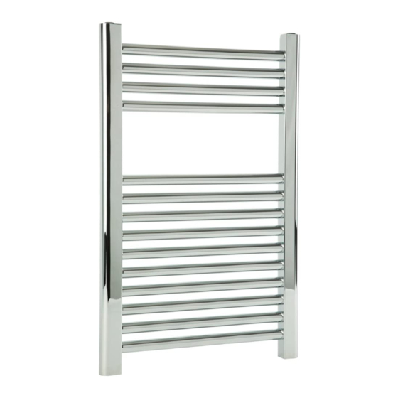
- Page 1 Installation Guide Denby Towel Warmer M06845H ( hydronic version )
- Page 2 Congratulations! You are the proud owner of a quality towel warmer. ARTOS The Denby Towel Rack is intended for towel warming/drying, auxiliary heating or as a decorative product. The average heat up time is about thirty minutes, but would depend on: a ) the size of the unit and b ) the initial temperature of the unit.
- Page 3 TECHNICAL SPECIFCATIONS Rev 04/11 MODEL# M06845 ELECTRIC VERSION Element specifications 200W, 110V, 48” cord, UL approved. Hardwire Kit CSA-US approved. File ref: 229718 HYDRONIC VERSION Heat ouput 1385 BTU. ½” BSPT tappings. Steel towel warmers should only be used in a closed water system, incorporating a rust inhibitor.
- Page 4 INSTALLATION STEPS 1. Check that all the installation pack contents have been received. There should be 3 items as shown below: Brackets Valve X 2 2. Determine location of towel warmer and install heating system pipework to proposed towel warmer location. Tee off the main circuit to provide a branch circuit for the towel warmer. Refer to page 3 for piping locations.
- Page 5 INSTALLATION STEPS Bracket Installation: 3. Attach bracket pieces 1,2,3, and 4 to towel warmer using diagram 1 below as a guide. Typically the brackets are positioned between the 2nd and 3rd bars from the top and bottom. To allow maximum hanging space for the towel, position brackets as near to the edges as possible.
- Page 6 INSTALLATION STEPS Valve Diagram NOTE: this diagram shows a PX40 angled valve. PX41 straight valves are also available. The same installation steps can be followed, but supply pipes must enter through the floor rather than through the wall. # 1 male stub Valve body #2 compression fitting...
- Page 7 Damage caused by accident, misuse, abuse, improper installation, improper cleaning or alteration will void the warranty. . Westover, Inc is not responsible for labor charges, installation or other incidental or consequential costs. PLEASE REGISTER THIS PRODUCT ONLINE AT WWW.ARTOS-WESTOVER.COM Item №: M06845H- Serial №...
Need help?
Do you have a question about the M06845H and is the answer not in the manual?
Questions and answers